Table of Contents
Advertisement
Quick Links
Advertisement
Table of Contents

Related Manuals for Gossen MetraWatt METRAHIT 2+


Summary of Contents for Gossen MetraWatt METRAHIT 2+
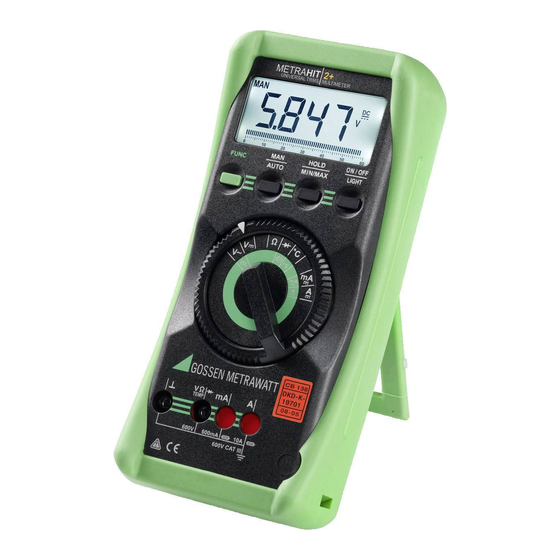
- Page 1 Operating Instructions METRAHIT2+ 3-349-476-03 Universal TRMS Multimeter 9/7.15...
- Page 2 Symbols used in the Digital Display MAN: manual measuring range selection is active MIN/MAX value storage HOLD: display memory, “freeze” measured value Digital display with decimal point and polarity display Diode measurement selected appears when acoustic signal is active Selected type of current Unit of measure Unit of measure °C / °F for temperature measurement Max.
-
Page 3: Table Of Contents
Table of Contents Manufacturer‘s Guarantee ........18 Page Product Support ............18 Safety Features and Precautions .......3 Initial Start-Up ............5 Safety Features and Precautions Selecting Measuring Functions and Measuring Ranges ..5 You have selected an instrument which provides you with a Automatic Measuring Range Selection ........ - Page 4 • Special care is required when measurements are made in Meanings of symbols on the instrument: HF electrical circuits. Dangerous pulsating voltages may Warning concerning a source of danger be present. (attention: observe documentation) • Measurements under moist ambient conditions are not permitted.
-
Page 5: Initial Start-Up
Initial Start-Up The instrument is automatically switched to: ± (6039 digits + 1 digit) – The next highest range at typically Battery ± (560 digits – 1 digit) – The next lowest range at typically Your instrument is supplied with two 1,5 V AA size batteries in accordance with IEC LR 6, and is ready for operation. -
Page 6: Relative Measurement Δ Rel
3.4 Relative Measurement Δ REL Display Illumination After the instrument has been switched on, background A reference value for relative measurements can be stored to illumination can be activated by briefly pressing the memory with the keys MAN / AUTO and HOLD. ON / OFF LIGHT key. -
Page 7: Voltage Measurement
Voltage Measurement ➭ Depending upon the voltage to be measured, set the rotary selector switch to V or V 20.00 ➭ Connect the measurement cables as shown. The “⊥” connector jack should be grounded. Note! The 600 mV measuring range can only be selected 6 V →... -
Page 8: Voltage Measurements At Above 600 V
Voltage Measurements at Above 600 V Voltages of greater than 600 V can be measured with a high- voltage probe, e.g. the HV3 or the HV30 from GMC-I 0.000 Messtechnik GmbH. It is absolutely essential to ground the ...6 A bonding terminal. - Page 9 connector jacks.The following symbol appears at the digital display in this case: • If a fuse blows, eliminate the cause of overload before 00.00 placing the instrument back into service! ... 60 mA • Refer to chapter 13 “Maintenance”, regarding fuse replacement.
-
Page 10: Measuring Alternating Current With (Clip-On) Current Transformers
Measuring Alternating Current with (Clip-On) Current Resistance Measurement Transformers ➭ Make sure that the device under test is voltage-free. Interference voltages distort measurement results! 8.1.1 Transformer Output mA / A ➭ Set the rotary selector switch to Ω. ➭ Connect the device under test as shown. Attention! If current transformers are operated without being Ω... -
Page 11: Continuity And Diode Testing
Continuity and Diode Testing ➭ Make sure that the device under test is voltage-free. Interference voltages distort measurement results! FUNC Ω 030.0 ➭ Set the rotary selector switch to ➭ Connect the device under test as shown. brief 0.000 0 V ! acoustic R <... -
Page 12: Temperature Measurement
Temperature Measurement The multimeter provides for the measurement of temperatures within a range of – 50 °C to + 400 °C with the help of a type K temperature sensor. ➭ Set the rotary selector switch to „°C“. ➭ Connect the sensor to the two accessible jacks. The device indicates the measured temperature in °C at the digital display. -
Page 13: Characteristic Values
Characteristic Values Intrinsic Error at Max. Resolution Reso- Overload Capacity under Reference Conditions Input Impedance Meas. Meas. lution Measuring Range ±(... % rdg. + ... d) ±(... % rdg. + ... d) Function Function 6000 Value Time 100 μV 600 mV 10 MΩ... - Page 14 Influencing Quantities and Influence Error Influencing Measuring Influencing Measured Quantity / Influence Error Sphere of Influence Damping Sphere of Influence Quantity Range ±(... % rdg. + ... digits) Quantity Measuring Range Interference quantity max. 600 V > 120 dB 600 mV 1.0 + 3 Common Mode...
- Page 15 Reference Conditions Electromagnetic Compatibility (EMC) + 23 °C ± 2 K Ambient temperature Interference emission EN 61326-1:2006 class B Relative humidity 40 % ... 60 % Interference immunity EN 61326-1:2006 EN 61326-2-1:2006 Measured quantity frequency 45 Hz ... 65 Hz Fuses Measured quantity Fuse links for all...
-
Page 16: Maintenance
Maintenance 13.2 Fuses Attention! If one of the fuses blows, this condition is displayed at the LCD as soon as a measured quantity with a voltage of greater Disconnect the instrument from the measuring circuit before opening to replace batteries or fuses! than 4 V is applied to the corresponding connector jacks. -
Page 17: Recalibration
If you use batteries or rechargeable batteries in your instrument Accessories or accessories which no longer function properly, they must be duly disposed of in compliance with the applicable 15.1 General national regulations. The extensive accessories available for our measuring Batteries or rechargeable batteries may contain harmful instruments are checked for compliance with currently valid substances or heavy metal such as lead (PB), cadmium (CD) -
Page 18: Repair And Replacement Parts Service, Calibration Center And Rental Instrument Service
Repair and Replacement Parts Service, DAkkS Calibration Certificate Reprints (upon request) Calibration Center* and Rental Instrument Service If you order a DAkkS calibration certificate reprint for your instrument, please provide us with the reference numbers If required please contact: indicated in the upper and lower most fields of the calibration seal.
Need help?
Do you have a question about the METRAHIT 2+ and is the answer not in the manual?
Questions and answers