
Related Manuals for Gossen MetraWatt METRAHIT EXTRA


Summary of Contents for Gossen MetraWatt METRAHIT EXTRA
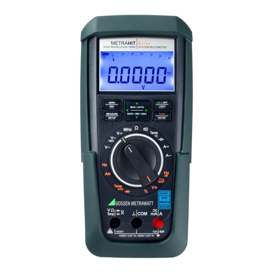
- Page 1 Operating Instructions E E E METRAHITE XTRA TECH SPECIAL BASE 3-349-456-03 High Resolution TRMS Digital Multimeter 8/10.12...
- Page 2 Standard Equipment Contact Persons Standard Equipment Function XTRA TECH SPECIAL BASE Capacitance measurement F — — 1 multimeter in HC20 hard case 600 A/6 mA Current A 1 KS17-S measurement cable set 60 mA/600 mA Current A TRMS 60 mA/600 mA 6 A/10 A (16 A) AC+DC 2 batteries...
- Page 3 Contact Persons Accessories (sensors, plug inserts, adapters, consumable materials) Product Support The accessories available for your instrument are checked for Technical Inquiries compliance with currently valid safety regulations at regular (use, operation, software registration) intervals, and are expanded as required for new applications. If required please contact: Currently up-to-date accessories which are suitable for your measuring instrument are listed at the following web address...
- Page 4 Standard Equipment Contact Persons Recalibration Service Accredited quantities: direct voltage, direct current value, direct current resistance, alternating voltage, alternating current value, AC active GMC-I Service GmbH will calibrate or recalibrate all instruments power, AC apparent power, DC power, capacitance, frequency, supplied by us or made by any other manufacturer.
- Page 5 Contact Persons Competent Partner GMC-I Messtechnik GmbH is certified in accordance with DIN EN ISO 9001:2008. Our DAkkS calibration laboratory is accredited by the Deutsche Akkreditierungsstelle GmbH (National accreditation body for the Republic of Germany) in accordance with DIN EN ISO/ IEC 17025:2005 under registration number D-K-15080-01-01.
-
Page 6: Table Of Contents
Table of Contents Contents Page Contents Page Safety Features and Precautions ........8 Measurements ..............26 Use for Intended Purpose ..............10 Voltage Measurement ..............26 Meanings of Danger Symbols ............10 5.1.1 Direct and Pulsating Voltage Measurement, V DC and V (DC+AC) ..27 Meanings of Acoustic Warning Signals ..........10 5.1.2 Alternating Voltage Measurement with 1 M Load Resistance... - Page 7 Table of Contents Contents Page Contents Page 5.7.2 Alternating Current and Frequency Measurement, Technical Data ..............56 Direct Connection, A AC and Hz (METRAHIT E , METRAHIT E XTRA TECH Maintenance and Calibration ..........64 METRAHIT E only) ............... 43 SPECIAL Displays – Error Messages ............64 5.7.3 Direct and Pulsating Current Measurement Batteries ..................
-
Page 8: Safety Features And Precautions
Safety Precautions Safety Features and Precautions Measuring Categories and their Significance per IEC 61010-1 You have selected an instrument which provides you with a high Definition level of safety. Measurements in electrical circuits which are not directly connected to the mains: This instrument fulfills the requirements of applicable European for example electrical systems in motor vehicles and aircraft, batteries etc. - Page 9 Safety Precautions • Be prepared for the occurrence of unexpected voltages at Repair and Parts Replacement devices under test (e.g. defective devices). For example, When the instrument is opened, voltage conducting parts may be capacitors may be dangerously charged. exposed. The instrument must be disconnected from the measur- •...
-
Page 10: Use For Intended Purpose
Safety Precautions 1.1 Use for Intended Purpose 1.2 Meanings of Danger Symbols • The respective multimeter is a portable device which can be Warning concerning a point of danger held in the hand during the performance of measurements. (attention: observe documentation!) •... - Page 11 Safety Precautions GMC-I Messtechnik GmbH...
-
Page 12: Operating Overview - Connections, Keys, Rotary Switch, Symbols
Operating Overview – Connections, Keys, Rotary Switch, Symbols Operating Overview – Connections, Keys, Rotary Switch, Symbols chapter 7 1 Display (LCD) (see page 13 for significance of symbols) 2 MAN / AUTO shift key for manual/automatic measuring range selection chapter 3.1 ... - Page 13 Operating Overview – Connections, Keys, Rotary Switch, Symbols Symbols Used in the Digital Display 1 Battery level indicator 10 11 2 ON: continuous operation (automatic shutdown deactivated) 3 MAN: manual measuring range selection is active 4 Digital display with decimal point and polarity display 5 max/min: Min/Max value storage 6 DATA: display memory, “freeze”...
- Page 14 Operating Overview – Connections, Keys, Rotary Switch, Symbols Symbols of Rotary Switch Positions Switch FUNC Display Measuring Function METRAHIT METRAHIT METRAHIT METRAHIT XTRA TECH SPECIAL BASE 0/4 V~ AC TRMS Alternating voltage, TRMS AC, full bandwidth ...
- Page 15 Operating Overview – Connections, Keys, Rotary Switch, Symbols s IR t User Interface Symbols in the Following Chapters Position of the infrared interface, window on the top of the instrument Scroll through main menu Scroll through sub-menu Position of the power pack connector socket, ...
-
Page 16: Initial Start-Up
Initial Start-Up – Setup Initial Start-Up Display Illumination After the instrument has been switched on, background illumina- 3.1 Inserting Batteries or Rechargeable Batteries tion can be activated by briefly pressing the ON / OFF | LIGHT key. Il- Be certain to refer to chapter 9.2 regarding correct battery lumination is switched back off by once again pressing the same installation. -
Page 17: Switching The Instrument Off
Initial Start-Up – Setup Ð 3.4 Switching the Instrument Off Switching the Instrument Off Manually / OFF Ð Press the ON / OFF | LIGHT key until 0FF appears at the display. LIGHT 8.8.8.8.8 Shutdown is acknowledged with a brief acoustic signal. Automatic Shutdown Auto-Range The instrument is switched off automatically if the measured value... -
Page 18: Control Functions
Control Functions Control Functions 4.1.2 Manual Measuring Range Selection Auto-ranging can be deactivated and measuring ranges can be 4.1 Selecting Measuring Functions and Measuring Ranges selected manually in accordance with the following table by The rotary switch is linked to the automatic socket blocking pressing the MAN / AUTO button. -
Page 19: Quick Measurements
Control Functions 4.1.3 Quick Measurements Zero balancing and reference value adjustment can be used for auto-ranging, as well as for manual measuring range selection. Measurements performed using a suitable fixed measuring range are executed more quickly than those which utilize automatic Zero Balancing range selection. -
Page 20: Display (Lcd)
Control Functions Ð Briefly press the ZERO | ESC key. 4.3.2 Analog Display The instrument acknowledges storage of the reference value Measured Value, Polarity with an acoustic signal, and the “ZERO REL” or the “REL” The analog display demonstrates the dynamic performance of a symbol appears at the LCD. -
Page 21: Measured Value Storage: Data (Auto-Hold / Compare)
Control Functions 4.4 Measured Value Storage: DATA (auto-hold / compare) An individual measured value can be automatically “frozen” with V, A, Hz dB, F, MHz, % of measuring range the DATA function (auto-hold). This is useful, for example, when 60,000 contacting the measuring points with the test probes requires your full attention. -
Page 22: Saving Minimum And Maximum Values - Min/Max Function
Control Functions Example The voltage measuring range is set manually to 6 V. Response from Instrument The first measured value is 3 V, which is stored to memory Press Display Min/Max Min. and Max. DATA / because it is greater than 5,000 digits of the measuring range Acoustic Function Measured Values... -
Page 23: Measurement Data Recording
Control Functions 4.5 Measurement Data Recording (METRAHIT E only) The STORE Menu Function XTRA The METRAHIT E is capable of recording measurement data Ð First set the sampling rate for memory mode operation (see rAtE XTRA using an adjustable sampling rate for long periods of time in the parameter in chapter 6.4) , and then start memory mode oper- form of measurement series. - Page 24 Control Functions During Recording Querying Memory Occupancy is displayed underneath the analog display during memory Memory occupancy can be queried during recording with the STORE mode operation, and memory occupancy can be controlled: help of the “1nFo ” menu (see also chapter 6.3). Memory occupancy range: 000.1% to 099.9%.
- Page 25 Control Functions GMC-I Messtechnik GmbH...
-
Page 26: Measurements
V/Hz, , Temperature, and A/Hz Measurements Measurements • Special care is required when measurements are made in HF electrical circuits. Dangerous pulsating voltages may be 5.1 Voltage Measurement present. Notes Regarding Voltage Measurement • Be aware of the fact that dangerous voltage spikes are not displayed •... -
Page 27: Direct And Pulsating Voltage Measurement, V Dc And V (Dc+Ac)
V/Hz, , Temperature, and A/Hz Measurements 5.1.1 Direct and Pulsating Voltage Measurement, V DC and V (DC+AC) Note 020.00 The following must be observed for all multimeters except for the METRAHIT E BASE Set the CL iP parameter to 0FF in the current clamp setup menu. -
Page 28: And Frequency Measurement With Selectable Low-Pass Filter
V/Hz, , Temperature, and A/Hz Measurements 5.1.2 Alternating Voltage Measurement with 1 M Load Resistance Frequency Measurement and Frequency Measurement with Selectable Low-Pass Filter Ð Apply the measured quantity is the same way as for voltage (METRAHIT E , METRAHIT E XTRA TECH measurement. - Page 29 V/Hz, , Temperature, and A/Hz Measurements Measuring Ranges: 1M Temp V~: 600 mV1000 V 0225.6 Max. 1000 V (< 10 kHz) 1kHz TRMS Max. 100 V (> 10 kHz) Hz: 1 Hz 300 kHz FUNC = 6 x 10 V x Hz ENTER V~ &...
-
Page 30: Alternating Voltage And Frequency Measurement V Ac And Hz With Selectable Low-Pass Filter
V/Hz, , Temperature, and A/Hz Measurements 5.1.3 Alternating Voltage and Frequency Measurement V AC and Hz Frequency Measurement with Selectable Low-Pass Filter Ð Apply the measured quantity is the same way as for voltage (METRAHIT E , METRAHIT E XTRA TECH measurement. - Page 31 V/Hz, , Temperature, and A/Hz Measurements Measuring Ranges: 0230.6 Temp V~: 600 mV1000 V Max. 1000 V (< 10 kHz) TRMS Max. 100 V (> 10 kHz) FUNC Hz: 1 Hz 300 kHz ENTER = 6 x 10 V x Hz for U >...
- Page 32 V/Hz, , Temperature, and A/Hz Measurements Alternating Voltage Level Measurement (dB) Note Voltage level measurement is used in order No terminal resistors have been integrated into the device. It to ascertain overall attenuation or boosting performs measurement with a high input impedance of of a transmission system (shown here as a 9 M.
-
Page 33: Transient Overvoltages
V/Hz, , Temperature, and A/Hz Measurements 5.1.4 Transient Overvoltages 5.1.5 Voltage Measurements at Above 1000 V The multimeters are protected against transient overvoltages of Voltages of greater than 1000 V can be measured with a up to 8 kV with wave-front durations of 1.2 ms and halftimes of high-voltage probe, e.g. -
Page 34: Frequency And Duty Cycle Measurements
V/Hz, , Temperature, and A/Hz Measurements 5.1.6 Frequency and Duty Cycle Measurements (METRAHIT E only) XTRA Ð Set the rotary switch to MHz or %. 1.0323 Ð Connect the measurement cables as shown. Make sure that a current measuring range (“A”) has not been activated when the multimeter is connected for frequency or duty cycle measurement! FUNC... -
Page 35: Resistance Measurement
V/Hz, , Temperature, and A/Hz Measurements 5.2 Resistance Measurement, Ð Disconnect supply power from the electrical circuit of the device to be measured, and discharge all high-voltage capacitors. 000.00 Ð Make sure that the device under test is voltage-free. Interference voltages distort measurement results! k... -
Page 36: Continuity Test
V/Hz, , Temperature, and A/Hz Measurements 5.3 Continuity Test Ð Disconnect supply power from the electrical circuit of the device to be measured, and discharge all high-voltage capacitors. 000.8 Ð Make sure that the device under test is voltage-free. Interference voltages distort measurement results! ... -
Page 37: Diode Testing With A Constant Current Of 1 Ma
V/Hz, , Temperature, and A/Hz Measurements 5.4 Diode Testing with a Constant Current of 1 mA Ð Disconnect supply power from the electrical circuit of the device to be measured, and discharge all high-voltage 000.8 capacitors. Ð Make sure that the device under test is voltage-free. ... -
Page 38: Temperature Measurement
V/Hz, , Temperature, and A/Hz Measurements 5.5 Temperature Measurement Note Temperature measurement is performed with a type K The internal reference temperature (temperature of the inter- thermocouple (accessory), which is connected to the voltage in- nal reference junction) is measured by a temperature sensor put. -
Page 39: Measurement With Resistance Sensors
V/Hz, , Temperature, and A/Hz Measurements 5.5.2 Measurement with Resistance Sensors (METRAHIT E and METRAHIT E only) XTRA TECH Temp Ð Set the rotary switch to “Temp ” or “Temp ”. 0023.3 The last selected temperature measurement or sensor, i.e. type K or Pt100/Pt1000, remains in memory and is accordingly ... -
Page 40: Only)
V/Hz, , Temperature, and A/Hz Measurements 5.6 Capacitance Measurement (METRAHIT E and METRAHIT E only) XTRA TECH Ð Disconnect supply power from the electrical circuit of the device to be measured, and discharge all high-voltage 10.38 capacitors. Ð Make sure that the device under test is voltage-free. ... -
Page 41: Current Measurement
V/Hz, , Temperature, and A/Hz Measurements 5.7 Current Measurement Scope of Functions, Current Measurement, Direct Connection Function METRAHIT METRAHIT METRAHIT METRAHIT Notes Regarding Current Measurement XTRA TECH SPECIAL BASE • The multimeter may only be operated with installed batteries or 600 A A AC / Hz rechargeable batteries. -
Page 42: Direct And Pulsating Current Measurement, Direct Connection
V/Hz, , Temperature, and A/Hz Measurements 5.7.1 Direct and Pulsating Current Measurement, Direct Connection, A DC and A (DC+AC) (METRAHIT E , METRAHIT E XTRA TECH METRAHIT E only) SPECIAL 003.50 Ð First disconnect supply power from the measuring circuit or the power consumer (1), and discharge any capacitors. -
Page 43: Metrahit Especial Only)
V/Hz, , Temperature, and A/Hz Measurements 5.7.2 Alternating Current and Frequency Measurement, Direct Connection, A AC and Hz (METRAHIT E , METRAHIT E XTRA TECH METRAHIT E only) 003.50 SPECIAL Ð First disconnect supply power from the measuring circuit or the power consumer (1), and discharge any capacitors. -
Page 44: Direct And Pulsating Current Measurement With Current Clamp Sensors, A Dc And A (Dc+Ac)
V/Hz, , Temperature, and A/Hz Measurements 5.7.3 Direct and Pulsating Current Measurement with Current Clamp Sensors, A DC and A (DC+AC) METRAHIT E BASE Transformer Output, Voltage/Current 1:1000 003.50 When a current clamp sensor is connected to the multimeter (V input (METRAHIT E : V input)), all current displays appear with BASE the correct value in accordance with the selected transformation fac-... -
Page 45: Alternating Current Measurement With Current Clamp Sensors, A Ac And Hz
V/Hz, , Temperature, and A/Hz Measurements 5.7.4 Alternating Current Measurement with Current Clamp Sensors, A AC and Hz METRAHIT E BASE Transformer Output, Voltage/Current 1:1000 When a current clamp sensor is connected to the multimeter 003.50 (V input (METRAHIT E : V input)), all current displays appear with BASE the correct value in accordance with the selected transformation fac-... -
Page 46: Direct, Pulsating And Current Measurement With Current Clamps
V/Hz, , Temperature, and A/Hz Measurements 5.7.5 Direct, Pulsating and Current Measurement with Current Clamps Transformer A DC, A (DC+AC), A AC and Hz (METRAHIT E XTRA METRAHIT E and METRAHIT E only) TECH SPECIAL Transformer Output, Current/Current When a current clamps transformer is connected to the multime- ter ( mA/A input), all current displays appear with the correct value in accordance with the selected transformation factor. - Page 47 V/Hz, , Temperature, and A/Hz Measurements GMC-I Messtechnik GmbH...
-
Page 48: Device And Measuring Parameters
Device and Measuring Parameters Device and Measuring Parameters After repeatedly pressing the MEASURE | SETUP key (without first turning the multimeter off), you can return to the last selected The instrument’s “SET ” mode (menu mode) makes it possible to menu or parameter from the measuring mode. -
Page 49: Paths To The Various Parameters
Device and Measuring Parameters 6.1 Paths to the Various Parameters 6.2 List of All Parameters Parameter E Page: Header XTRA TECH BASE CIAL diSP 51: 0.diSP – show/hide leading zeros MEASURE Addr 020.00 1nfo — 55: Configuring Interface Parameters —... -
Page 50: Querying Parameters - Info Menu (As Moving Letters)
Device and Measuring Parameters 6.3 Querying Parameters – InFo Menu (as moving letters) 6.4 Entering Parameters – SETUP Menu bAtt – query battery voltage rAtE – set the sampling rate (METRAHIT E only) XTRA MEASURE FUNC 1nFo bAtt: 2.75 V. The sampling rate specifies the time interval after which the SETUP ENTER... - Page 51 Device and Measuring Parameters 0.diSP – show/hide leading zeros APoFF – specified time for automatic shutdown and continuous ON This parameter determines whether or not leading zeros will The instrument is switched off automatically if the measured value appear in the measured value display. remains unchanged for a long period of time, and if none of the keys or the rotary switch have been activated before the specified MEASURE...
- Page 52 Device and Measuring Parameters bEEP – set the limit value for continuity testing dAtE – enter date Entering the current date makes it possible to acquire measured MEASURE FUNC values in real-time. 1nFo rAtE bEEP SETUP ENTER FUNC FUNC...
-
Page 53: Default Settings
Device and Measuring Parameters 6.5 Default Settings Previously entered changes can be undone, and the default settings can be reactivated. This may be advisable under the following circumstances: • After the occurrence of software or hardware errors • If you are under the impression that the multimeter does not work correctly Ð... -
Page 54: Interface Operation
Interface Operation Interface Operation Starting Continuous Transmission Operation with Menu Functions The multimeters are equipped with an infrared interface for the MEASURE FUNC FUNC transmission of measurement data to a PC. Measured data are 1nFo SEnd StArt send SETUP ENTER ENTER... -
Page 55: Configuring Interface Parameters
Interface Operation Addr – Address 7.2 Configuring Interface Parameters If several multimeters are connected to the PC via an interface irStb – status of the infrared receiver in the stand-by mode adapter, a separate address can be assigned to each instrument. Address number 1 should be selected for the first instrument, 2 There are two possible switching statuses for the infrared should be assigned to the second and so forth. -
Page 56: Technical Data
Technical Data Technical Data Intrinsic Error under Reference Conditions for High Resol 59999 digits Resolution at Upper Input Impedance Overload Capacity Meas. (... % rdg. + ... d) (... % rdg. + ... d) (... % rdg. + ... d) Range Limit Measuring Range Function... - Page 57 Technical Data Intrinsic Error under Reference Conditions for High Resol 59999 digits Resolution at Upper Input Impedance Overload Capacity Meas. (... % rdg. + ... d) (... % rdg. + ... d) (... % rdg. + ... d) Range Limit Measuring Range Function 59 999...
- Page 58 Technical Data Resolution at Upper Overload Input Impedance Meas. Intrinsic Error under Reference Conditions for Range Limit Capacity Measuring Range Function High Resol 59999 digits 59999 5999 Value Time (... % rdg. + ... d) Discharge resist. 0 max — 10 pF 10 M...
- Page 59 Technical Data Influencing Quantities and Influence Error Intrinsic Error ... % rdg. + ... d) Influencing Sphere of Measured Quantity / Influence Error Influencing Meas. Quantity/ Quantity Influence Measuring Range (...% rdg. + ... d) / 10 K Sphere of Influence METRAHIT E XTRA Quantity...
- Page 60 Technical Data Reference Conditions Influencing Sphere of Measured Quantity / Influence Error +23C 2 K Quantity Influence Measuring Range Ambient temperature 1 % rdg. 1 ... 3 Relative humidity 40 ... 75% Crest factor CF 3 % rdg. >...
- Page 61 Technical Data Data Interface Power Supply Type Optical via infrared light through the Battery 2 ea. 1.5 V mignon cell (2 ea. size AA), housing alkaline manganese per IEC LR6 (2 ea. 1.2 V NiMH rechargeable battery Data transmission also possible) (data transfer) Serial, bidirectional (not IrDa compatible) Service life...
- Page 62 Technical Data Display Acoustic Signals LCD panel (65 mm x 36 mm) with analog and digital display For voltage Intermittent signal at above 1000 V including unit of measure, type of current and various special For current Intermittent signal at above 10 A functions Continuous signal at above 16 A Background illumination...
- Page 63 Technical Data Electromagnetic Compatibility (EMC) Mechanical Design Interference Housing Impact resistant plastic (ABS) emission EN 61326-1: 2006, class B Dimensions 200 x 87 x 45 mm Interference (without protective rubber cover) immunity EN 61326-1: 2006 Weight Approx. 0.35 kg with batteries EN 61326-2-1: 2006 Protection Housing: IP 52...
-
Page 64: Maintenance And Calibration
Maintenance – Calibration Maintenance and Calibration Battery The current battery charge level can be queried in the “1nfo” Attention! Disconnect the instrument from the measuring circuit before menu: opening the battery compartment lid or fuse cover in order to replace batteries or fuses! MEASURE FUNC 1nFo... -
Page 65: Fuse (Metrahit Extra And Metrahit Etech Only)
Maintenance – Calibration Replacing the Batteries If the fuse is blown or has not been inserted, “FuSE” appears at the digital display. The fuse interrupts the current measuring ranges. All other measuring ranges remain functional. Attention! Disconnect the instrument from the measuring circuit before opening the battery compartment lid in order to replace the batteries. -
Page 66: Housing Maintenance
Maintenance – Calibration 9.4 Housing Maintenance No special maintenance is required for the housing. Keep outside Attention! Use specified fuses only! surfaces clean. Use a slightly dampened cloth for cleaning. Avoid If fuses with other blowing characteristics, other current the use of cleansers, abrasives or solvents. ratings or other breaking capacities are used, the operator 9.5 Return and Environmentally Sound Disposal is placed in danger, and protective diodes, resistors and... -
Page 67: Recalibration
Maintenance – Calibration 9.6 Recalibration 9.7 Manufacturer’s Guarantee The respective measuring task and the stress to which your measur- All METRA HIT measuring and calibration instruments are ing instrument is subjected affect the ageing of the components and guaranteed for a period of 3 years after date of shipment. The may result in deviations from the guaranteed accuracy. -
Page 68: Accessories
Accessories 10 Accessories 10.1 General Application KS17-2 The extensive accessories available for our measuring instruments are checked for compliance with currently valid safety Attention! regulations at regular intervals, and are expanded as required for In conformity with standard DIN EN 61010-031, mea- new applications. -
Page 69: Interface Accessories (Not Included)
Accessories 10.4 Interface Accessories (not included) USB X-TRA Bidirectional Interface Adapter This adapter makes it possible to connect multimeters of the STARLINE series which are equipped with a serial IR interface to the USB port at a PC. The adapter allows for data transmission between the multimeter and the PC. -
Page 70: Index
Index Index Numerics Measuring Range Selection 0.diSP dAtE ..............51 ..............50, 52 Automatic ............18 dbrEF ..............51 Manual ............18 Default Settings ............ 53 Memory A.diSP ..............51 Diode Test ............. 37 Ending Recording ......... 24 Addr ..............55 Display Illumination .......... - Page 71 Index Safety Precautions ..........8 Software Enabling ..........3 Standard Equipment ..........2 Switching the Instrument On Manual ............16 Via PC ............16 Symbols Digital Display ..........13 Instrument .............15 Rotary Switch Positions ........14 Temperature Measurement With Resistance Thermometers ....39 With Thermocouples ........38 tiME ..............
- Page 72 Edited in Germany Subject to change without notice A pdf version is available on the internet Phone +49 911 8602-111 GMC-I Messtechnik GmbH +49 911 8602-777 Südwestpark 15 E-Mail info@gossenmetrawatt.com 90449 Nürnberg • Germany www.gossenmetrawatt.com...
Need help?
Do you have a question about the METRAHIT EXTRA and is the answer not in the manual?
Questions and answers