Sign In
Upload
Download
Table of Contents
Contents
Add to my manuals
Delete from my manuals
Share
URL of this page:
HTML Link:
Bookmark this page
Add
Manual will be automatically added to "My Manuals"
Print this page
×
Bookmark added
×
Added to my manuals
Manuals
Brands
Gossen MetraWatt Manuals
Multimeter
METRA HIT 27M
Operating instructions manual
Gossen MetraWatt METRA HIT 27M Operating Instructions Manual
Hide thumbs
Also See for METRA HIT 27M
:
Operating instructions manual
(60 pages)
1
2
Table Of Contents
3
4
5
6
7
8
9
10
11
12
13
14
15
16
17
18
19
20
21
22
23
24
25
26
27
28
page
of
28
Go
/
28
Contents
Table of Contents
Bookmarks
Table of Contents
Table of Contents
1 Safety Features and Precautions
2 Initial Start-Up
3 Selecting Measuring Functions and Measuring Ranges
Automatic Measuring Range Selection
Manual Measuring Range Selection
Quick Measurements
4 Triple Digital Display
5 Measured Value Storage
Measured Value Storage - Key Function "DATA" (Hold/Compare)
6 Saving Minimum and Maximum Values "MIN/MAX" with Time Stamp
7 Voltage and Frequency Measurement
Voltage Measurement [V]
Zero Balancing in the 3 V DC Measuring Range
Transient Overvoltages
Voltage Measurements at above 600 V
Frequency Measurement [Hz]
8 Resistance and Diode Measurements
Resistance Measurement (2-Wire Connection) [Ω]
Zero Balancing in the 300 Ω and 3 Kω Measuring Ranges
Continuity Test During Resistance Measurement
Diode Measurements
9 Milliohm Measurement (4-Pole-Measurement)
Compensation of Cable Resistance
Measurement with Kelvin Probe KC27
Thermovoltage Compensation
Milliohm Measurement with 200 Ma or 20 Ma DC [Mω]
Milliohm Measurement with 1 a Pulsating Measuring Current [Mω@1 A] (Automatic Thermovoltage Correction in 3
10 Temperature Measurement [°C]
(METRA HIT 27I and METRA HIT H+ECAR Only)
Preparing for Measurement
11 Insulation Resistance Measurement [MΩ
Insulation Resistance Measurement
Ending the Measurement and Discharging
12 Using the Menus - from the Initial Info Menu to Operating and Measuring Parameters
Sampling Rate
Saving Measured Values
1Memory Mode - DATA Key Function (See also Chapter 5.1)
2Memory Mode Operation - STORE Menu Function
Querying Memory Occupancy - INFO MEMO/OCCUP
Clearing the Memory - MEMO Clear
Activating the Default Values
Transmission Mode Operation with RS 232 Interface
13 Characteristic Values
14 Maintenance
Storage Batteries and Batteries
Fuses
Housing
Device Return and Environmentally Compatible Disposal
15 Multimeter Messages
16 Accessories
17 Repair and Replacement Parts Service, Calibration Center and Rental Instrument Service
18 Guarantee
19 Product Support
20 Recalibration
Advertisement
Quick Links
1
Initial Start-Up
2
Milliohm Measurement (4-Pole-Measurement)
3
Insulation Resistance Measurement [Mω
4
Recalibration
Download this manual
Operating Instructions
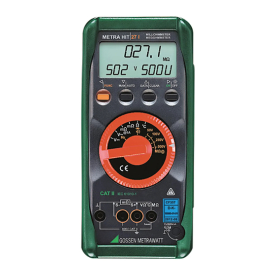
METRAHIT⏐27 and METRAHIT⏐H+E
METRA HIT 27M:
METRA HIT 27I:
METRA HIT H+E
CAR
Digital Multimeter and Milliohmmeter
Digital Multimeter, Milliohmmeter and Megohmmeter
: Mega Tester for Hybrid E-cars
CAR
3-349-207-02
12/4.16
Table of
Contents
Previous
Page
Next
Page
1
2
3
4
5
Advertisement
Table of Contents
Need help?
Do you have a question about the METRA HIT 27M and is the answer not in the manual?
Ask a question
Questions and answers
Related Manuals for Gossen MetraWatt METRA HIT 27M
Measuring Instruments Gossen MetraWatt METRA HIT 22S Operating Instructions Manual
Analog digital multimeter with signalgenerator (60 pages)
Multimeter Gossen MetraWatt METRAHIT ISO Operation Manual
Trms multimeter with insulation measurement (70 pages)
Multimeter Gossen MetraWatt METRAHIT ENERGY TRMS System Multimeter Operating Instructions Manual
Trms system multimeter; metrahit energy; (98 pages)
Multimeter Gossen MetraWatt METRAHIT X-tra Operating Instructions
Trms digital multimeter (2 pages)
Multimeter Gossen MetraWatt METRAHIT X-TRA Operating Instructions Manual
(70 pages)
Multimeter Gossen MetraWatt METRAHIT X-tra Operating Instructions
Trms digital multimeter (2 pages)
Multimeter Gossen MetraWatt METRAHIT EXTRA Operating Instructions Manual
High resolution trms digital multimeter (72 pages)
Multimeter Gossen MetraWatt METRAHIT PM TECH Operating Instructions Manual
Professional multimeters / special multimeters (68 pages)
Multimeter Gossen MetraWatt METRAHIT 2+ Operating Instructions Manual
Trms digital multimeter with analog bar graph and temperature measuring instrument (18 pages)
Multimeter Gossen MetraWatt METRACAL MC Operating Instructions Manual
Calibrator (84 pages)
Multimeter Gossen MetraWatt METRAHIT ULTRA Operating Instructionsc
High resolution trms digital multimeter (74 pages)
Multimeter Gossen MetraWatt METRAHIT ULTRA Operating Instructions
High resolution trms system multimeter (2 pages)
Multimeter Gossen MetraWatt METRAHIT T-COM PLUS Operating Instructions Manual
Cable multimeter for measurements in symmetrical copper cable networks (76 pages)
Multimeter Gossen MetraWatt METRAHIT AM PRO Operating Instructions Manual
Advanced multimeters; special multimeters (61 pages)
Multimeter Gossen MetraWatt METRAHIT IM XTRA Operating Instructions Manual
(24 pages)
Multimeter Gossen MetraWatt METRAHIT IM XTRA BT Short-Form Operating Instructions
(36 pages)
This manual is also suitable for:
Metra hit 27i
Metra hit h+e car
M227a
M227b
M227c
M227s
...
Show all
M227t
M227u
Table of Contents
Save PDF
Print
Rename the bookmark
Delete bookmark?
Delete from my manuals?
Login
Sign In
OR
Sign in with Facebook
Sign in with Google
Upload manual
Upload from disk
Upload from URL


Need help?
Do you have a question about the METRA HIT 27M and is the answer not in the manual?
Questions and answers