
Related Manuals for Gossen MetraWatt METRAHIT ULTRA


Summary of Contents for Gossen MetraWatt METRAHIT ULTRA
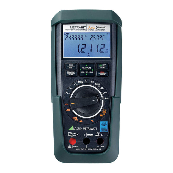
- Page 1 Operating Instructions METRAHITU METRAHITU LTRA LTRA 3-349-684-03 High Resolution TRMS Digital Multimeter 8/1.17...
- Page 2 Scope of Delivery Contact Persons Scope of Delivery Function METRAHIT ULTRA / METRAHIT ULTRA BT 1 Multimeter M248A / M248B 1 KS17-2 measurement cable set 2 Batteries Current, A 300 A / 3 mA 1 Condensed operating instructions Current, A...
- Page 3 Contact Persons Accessories (sensors, plug inserts, adapters, consumable materials) Product Support The accessories available for your instrument are checked for Technical Queries compliance with currently valid safety regulations at regular inter- (use, operation, software registration) vals, and are amended as required for new applications. Currently If required please contact: up-to-date accessories which are suitable for your measuring in- GMC-I Messtechnik GmbH...
- Page 4 Scope of Delivery Contact Persons Recalibration Service Competent Partner Our service center calibrates and recalibrates all instruments sup- GMC-I Messtechnik GmbH is certified in accordance with plied by GMC-I Messtechnik GmbH, as well as other manufactur- DIN EN ISO 9001. ers, (for example after one year as part of your test equipment Our DAkkS calibration laboratory is accredited by the Deutsche monitoring system, and prior to use etc.) and offers free test...
- Page 5 Contact Persons GMC-I Messtechnik GmbH...
-
Page 6: Table Of Contents
Table of Contents Content Page Content Page Safety Features and Precautions ........8 Measurements ..............28 Use for Intended Purpose ..............10 Voltage Measurement ..............28 Meanings of Danger Symbols ............11 5.1.1 Direct and Pulsating Voltage Measurement, V DC and V (DC+AC) ..29 Meanings of Acoustic Warning Signals ..........11 5.1.2 Alternating Voltage and Frequency Measurement V AC and Hz V AC with Selectable Low-Pass Filter, V AC + FiL and dB V AC ..31... - Page 7 Table of Contents Content Page Content Page Device and Measuring Parameters ........48 10.4.1 Infrared Interface ................71 10.4.2 Bluetooth Interface ................ 71 Paths to the Various Parameters ............ 49 List of All Parameters ..............49 Querying Parameters – InFo Menu ..........50 Index .................72 Entering Parameters –...
-
Page 8: Safety Features And Precautions
Safety Precautions Safety Features and Precautions Hazardous touch voltages are not detected when the ohm or capacitance measurement is selected. You have selected an instrument which provides you with high If the instrument switches itself off in the event that hazardous levels of safety. - Page 9 Safety Precautions • The multimeter may only be operated by persons who are ca- • Be absolutely certain that the measuring ranges are not over- pable of recognizing touch hazards and taking the appropriate loaded beyond their allowable capacities. Limit values are in- safety precautions.
-
Page 10: Use For Intended Purpose
Safety Precautions Opening of Equipment / Repair 1.1 Use for Intended Purpose • The multimeter is a portable device which can be held in the The equipment may be opened only by authorized service per- hand during the performance of measurements. sonnel to ensure the safe and correct operation of the equipment and to keep the warranty valid. -
Page 11: Meanings Of Danger Symbols
Safety Precautions 1.2 Meanings of Danger Symbols 1.3 Meanings of Acoustic Warning Signals Warning concerning a point of danger Voltage warning: > 600 V (intermittent acoustic signal) (attention, observe documentation!) Symbol on the LCD: Current warning: > 10 A (intermittent acoustic signal) Warning concerning dangerous voltage at the measurement input: U >... -
Page 12: Operating Overview - Connections, Keys, Rotary Switch, Symbols
Operating Overview – Connections, Keys, Rotary Switch, Symbols Operating Overview – Connections, Keys, Rotary Switch, Symbols section 7 1 Display (LCD) (see page 14 for significance of symbols) section 3.1 2 MAN / AUTO shift key for manual/automatic range selection ... - Page 13 Operating Overview – Connections, Keys, Rotary Switch, Symbols Symbols Used in the Digital Display 1 Battery level indicator 2 ON: continuous operation (automatic shutdown deactivated) 3 DATA: display memory, “freeze measured value” 4 STORE: memory mode active 5 FILTER: low-pass filter active 6 IR: infrared interface indicator 7 Bluetooth interface control display 8 Auxiliary display: digital display with decimal point and polarity display...
- Page 14 Operating Overview – Connections, Keys, Rotary Switch, Symbols Symbols Used for Rotary Switch Positions Switch FUNC Main Display Auxiliary Display Measuring Function 0/4 V~ AC TRMS Alternating voltage, AC TRMS, full bandwidth / voltage frequency Hz (V) V~ AC Voltage frequency, up to 300 kHz / alternating voltage, AC TRMS V FILTER ~ AC TRMS Alternating voltage, AC TRMS, with low pass filter (1 kHz) / voltage frequency 1kHz...
- Page 15 Operating Overview – Connections, Keys, Rotary Switch, Symbols s IR t User Interface Symbols in the Following Sections Position of the infrared interface, window on the top of the instrument Scroll through main menu Scroll through submenu Position of the power pack adapter socket, ...
-
Page 16: Initial Start-Up
Note Operation with the Power Pack Electrical discharge and high frequency interference may (accessory for METRAHIT ULTRA, not included, see section 10.3) cause incorrect displays to appear, and may disable the measuring sequence. Installed batteries are disconnected electronically if the NA X-TRA Disconnect the device from the measuring circuit. -
Page 17: Switching The Instrument Off
Initial Start-Up – Setup 3.4 Switching the Instrument Off Switching the Instrument Off Manually / OFF Ð Press the ON / OFF | LIGHT key until 0FF appears at the display. LIGHT 8.8.8.8.8 Shutdown is acknowledged with a brief acoustic signal. If hazardous contact voltage has been detected (HV symbol appears), the instrument cannot be switched off. -
Page 18: Control Functions
Control Functions Control Functions sampling period), the high-voltage warning symbol remains visible at the display. 4.1 Selecting Measuring Functions and Measuring Ranges The rotary switch is linked to the automatic socket blocking mechanism, which only allows access to two connector jacks for 4.1.1 Automatic Range Selection each function. -
Page 19: Manual Measuring Range Selection
Control Functions 4.1.2 Manual Measuring Range Selection Auto-ranging can be deactivated and measuring ranges can be selected manually in accordance with the following table by pressing the MAN / AUTO button. The desired measuring range can then be selected with the ... -
Page 20: Quick Measurements
Control Functions 4.1.3 Quick Measurements Zero balancing and reference value adjustment can be used for auto-ranging, as well as for manual measuring range selection. Measurements performed using a suitable fixed measuring range are executed more quickly than those which utilize automatic Zero Balancing range selection. -
Page 21: Display (Lcd)
Control Functions Ð Briefly press the ZERO | ESC key. The instrument acknowledges storage of the reference value with an acoustic signal, and the “ZERO REL” or the “REL” symbol appears at the LCD. The value measured at the mo- ment the key is pressed serves as a reference value. -
Page 22: Measured Value Storage: Data (Auto-Hold / Compare)
Control Functions 4.4 Measured Value Storage: DATA (auto-hold / compare) V, A, Hz An individual measured value can be automatically “frozen” with of Measuring Range the DATA function (auto-hold). This is useful, for example, when 300000 100 % contacting the measuring points with the test probes requires your full attention. -
Page 23: Saving Minimum And Maximum Values - Min/Max Function
Control Functions Example The voltage measuring range is set manually to 3 V. The first mea- Response from Instrument Press sured value is 2.2 V and is stored to memory because it is greater Function Min. and Max. Display Acous- DATA / Min-Max Measured Values... -
Page 24: Measurement Data Recording
USB X-TRA bidirectional inter- StoP 25: Ending Recording face adapter, which is plugged onto the METRAHIT ULTRA. trig 54: triG – Trigger Conditions (parameters for memory mode operation) See also section 7, “Interface Operation”. - Page 25 Control Functions Ending Recording Querying Memory Occupancy Ð If the instrument is in the measuring mode, return to the menu Memory occupancy can be queried during recording with the help of the “1nFo” menu (see also section 6.3). function by pressing the MEASURE | SETUP key. Select “StorE” again and acknowledge by pressing the FUNC | ENTER key.
-
Page 26: Storage Of Individual Values Using The Sample Or Data Sampling Rate
Control Functions 4.5.2 Storage of Individual Values using the SAMPLE or dAtA Sampling Rate If only individually selected values need to be saved, SAMPLE must be selected as the StorE > rAtE sampling value. If memory mode operation is then started, a single measured value is saved to per- manent memory with time stamp when the DATA/MIN/MAX key is pressed and held until two rapidly repeating acoustic signals are generated. - Page 27 Control Functions GMC-I Messtechnik GmbH...
-
Page 28: Measurements
Be certain that a second person is present. V DC (Ri = 10 M) • For the METRAHIT ULTRA, maximum allowable voltage between the Pulse frequency, MHz @ 5 V TTL connector sockets and ground is 600 V for measuring cate- ... -
Page 29: Direct And Pulsating Voltage Measurement, V Dc And V (Dc+Ac)
V/Hz/dB – , Temperature, and A/Hz Measurements 5.1.1 Direct and Pulsating Voltage Measurement, V DC and V (DC+AC) CL ip = 0FF ! Note Set the CL iP parameter to 0FF in the current clamp setup menu. Otherwise all measured values are displayed in 0020.00 amperes, corrected by the amount resulting from the selected transformation ratio for an interconnected current... - Page 30 V/Hz, , Temperature, and A/Hz Measurements Frequency Measurement in the V (DC+AC) Switch Position Ð Connect the measured quantity in the same way as for voltage CL ip = 0FF ! 050.000 measurement. Ð Manually select the measuring range for the voltage amplitude. TRMS Ð...
-
Page 31: Alternating Voltage And Frequency Measurement V Ac And Hz
V/Hz/dB – , Temperature, and A/Hz Measurements 5.1.2 Alternating Voltage and Frequency Measurement V AC and Hz Frequency Measurement V AC with Selectable Low-Pass Filter, V AC + FiL and dB V AC Ð Connect the measured quantity in the same way as for voltage measurement. - Page 32 V/Hz, , Temperature, and A/Hz Measurements The active low-pass filter is indicated by the FILTER display. The multimeter is automatically switched to manual measuring range selection. 050.000 Specified measuring accuracy is not reached with signals of 1kHz greater than 100 Hz when the filter is active. TRMS FUNC Measuring Ranges:...
- Page 33 V/Hz/dB – , Temperature, and A/Hz Measurements Alternating Voltage Level Measurement (dB) Note Voltage level measurement is used in order to No terminal resistors have been integrated into the device. It ascertain overall attenuation or boosting of a performs measurement with a high input impedance of transmission system (shown here as a 4-pole 5 M.
-
Page 34: Transient Overvoltages
V/Hz, , Temperature, and A/Hz Measurements 5.1.3 Transient Overvoltages 5.1.4 Voltage Measurements at Above 600 V The multimeters are protected against transient overvoltages of Voltages of greater than 600 V can be measured with a high-volt- up to 6 kV with wave-front durations of 1.2 ms and halftimes of 50 age probe, e.g. -
Page 35: Frequency And Duty Cycle Measurement
V/Hz/dB – , Temperature, and A/Hz Measurements 5.1.5 Frequency and Duty Cycle Measurement Ð Set the rotary switch to MHz or %. Ð Connect the measurement cables as shown. 01.0323 Make sure that a current measuring range (“A”) has not been acti- vated when the multimeter is connected for frequency or duty cycle measurement! FUNC... -
Page 36: Resistance Measurement
V/Hz, , Temperature, and A/Hz Measurements 5.2 Resistance Measurement Ð Disconnect supply power from the electrical circuit of the de- vice to be measured, and discharge all high-voltage capaci- tors. 000.000 Ð Make sure that the device under test is voltage-free. Interfer- ence voltages distort measurement results! ... -
Page 37: Continuity Test With Constant Current Of 1 Ma
V/Hz/dB – , Temperature, and A/Hz Measurements 5.3 Continuity Test with Constant Current of 1 mA Ð Disconnect supply power from the electrical circuit of the de- vice to be measured, and discharge all high-voltage capaci- tors. 000.8 Ð Make sure that the device under test is voltage-free. Interfer- ence voltages distort measurement results! ... -
Page 38: Diode Testing With Constant Current Of 1 Ma
V/Hz, , Temperature, and A/Hz Measurements 5.4 Diode Testing with Constant Current of 1 mA Ð Disconnect supply power from the electrical circuit of the de- vice to be measured, and discharge all high-voltage capaci- 000.8 tors. Ð Make sure that the device under test is voltage-free. Interfer- ... -
Page 39: Temperature Measurement
V/Hz/dB – , Temperature, and A/Hz Measurements Ð Connect the sensor to the two accessible jacks. The instru- 5.5 Temperature Measurement ment displays the measured temperature using the selected Temperature measurement is performed with a type K thermocouple or a unit of measure. -
Page 40: Measurement With Resistance Sensors
V/Hz, , Temperature, and A/Hz Measurements Ð Upon pressing the FUNC | ENTER key, the selected value is acti- 5.5.2 Measurement with Resistance Sensors vated and the display is returned to the measuring function. Ð Set the rotary switch to “Temp ”... -
Page 41: Capacitance Measurement
V/Hz/dB – , Temperature, and A/Hz Measurements 5.6 Capacitance Measurement Note Ð Disconnect supply power from the electrical circuit of the de- This function is above all intended for the measurement of vice to be measured, and discharge all high-voltage capaci- components. -
Page 42: Current Measurement
V/Hz, , Temperature, and A/Hz Measurements 5.7 Current Measurement • Be absolutely certain that the measuring ranges are not over- loaded beyond their allowable capacities. Limit values are in- Notes Regarding Current Measurement cluded in section 8, “Technical Data”, in the table entitled •... -
Page 43: Direct And Pulsating Current Measurement, Direct Connection, Adc And A (Dc+Ac)
V/Hz/dB – , Temperature, and A/Hz Measurements 5.7.1 Direct and Pulsating Current Measurement, Direct Connection, A DC and A (DC+AC) 24. 6 ° C Ð First disconnect supply power from the measuring circuit or 002.500 the power consumer, and discharge any capacitors. Ð... -
Page 44: Alternating Current And Frequency Measurement, Direct Connection, A Ac And Hz
V/Hz, , Temperature, and A/Hz Measurements 5.7.2 Alternating Current and Frequency Measurement, Direct Connection, A AC and Hz 015.000 24. 6 ° C Ð First disconnect supply power from the measuring circuit or 03.500 the power consumer, and discharge any capacitors. Ð... -
Page 45: Direct And Pulsating Current Measurement With Current Clamp Sensor, Adc And A (Dc+Ac)
V/Hz/dB – , Temperature, and A/Hz Measurements 5.7.3 Direct and Pulsating Current Measurement with Current Clamp Sensor, A DC and A (DC+AC) Voltage/Current Transformer Output 1:1000 003.500 When a current clamp sensor is connected to the multimeter (V put), all current displays appear with the correct value in accordance with the selected transformation ratio. -
Page 46: Alternating Current Measurement With Current Clamp Sensor
V/Hz, , Temperature, and A/Hz Measurements 5.7.4 Alternating Current Measurement with Current Clamp Sensor, A AC and Hz Voltage/Current Transformer Output 015.000 1:1000 When a current clamp sensor is connected to the multimeter (V 003.50 input), all current displays appear with the correct value in accor- dance with the selected transformation ratio. -
Page 47: Alternating Current Measurement With Current Clamp Transformer, A Ac And Hz
V/Hz/dB – , Temperature, and A/Hz Measurements 5.7.5 Alternating Current Measurement with Current Clamp Transformer, A AC and Hz Current/Current Transformer Output When a current clamp transformer is connected to the multimeter mA/A input), all current displays appear with the correct value in accordance with the selected transformation ratio. -
Page 48: Device And Measuring Parameters
Device and Measuring Parameters Device and Measuring Parameters After repeatedly pressing the MEASURE | SETUP key (without first turning the multimeter off), you can return to the last selected The instrument’s “SET” mode (menu mode) makes it possible to menu or parameter from the measuring mode. set operating and measuring parameters, query information and activate the interface. -
Page 49: Paths To The Various Parameters
Device and Measuring Parameters 6.1 Paths to the Various Parameters 6.2 List of All Parameters Parameter Page: Header Addr 57: Configuring Interface Parameters APoFF 51: APoFF – Specified Time for Automatic Shutdown and Continuous ON MEASURE 020.00 1nfo bAtt 50: bAtt – Query Battery Voltage SETUP bEEP 52: bEEP –... -
Page 50: Querying Parameters - Info Menu
Device and Measuring Parameters 6.3 Querying Parameters – InFo Menu Page: Header Parameter 50: vErSion – Query Firmware Version bAtt – Query Battery Voltage MEASURE FUNC 1nFo bAtt 2.9 V. SETUP ENTER OCCUP – Query Memory Occupancy MEASURE FUNC bAtt ... 0CCvP 000.0 % 1nFo SETUP ENTER... -
Page 51: Entering Parameters - Setup Menu
Device and Measuring Parameters 6.4 Entering Parameters – SETUP Menu cALdAt – Query Calibration Date tiME – Set Time MEASURE FUNC bAtt ... caldat 20.06.12 1nFo SETUP ENTER Entering the correct time makes it possible to acquire measured values in real-time. - Page 52 Device and Measuring Parameters CoM ir / CoM bt – Interface Operating System Infrared / Bluetooth CLiP – Set Transformation Ratio (current clamp factor) Refer to section 7.2 on page 57 for instructions on switching bet- See section 5.7.3 ff. ween the two systems.
-
Page 53: Store Menu - Parameter For Memory Mode Operation
Device and Measuring Parameters 6.5 StorE Menu – Parameter for Memory Mode Operation tEMP intErn/ExtErn – Select Internal or External Reference Junction External Reference Junction: Specified Temperature HYSt – Hysteresis (parameter for memory mode operation) The hysteresis setting allows for efficient use of memory space. MEASURE FUNC 1nFo... - Page 54 Device and Measuring Parameters Storage of Individual Values using the SAMPLE or dAtA Sampling Rate rAtE – Set Transmission and Storage Rate If only manually selected values need to be saved, SAMPLE must The sampling rate specifies the time interval after which the be selected as the StorE >...
-
Page 55: Default Settings
Device and Measuring Parameters V AC with 30,000 digits), it is not useful to set the trigger thresh- 6.6 Default Settings old above this measuring range span. It’s thus advisable to per- Previously entered changes can be undone, and default settings form measurement with a fixed measuring range. -
Page 56: Interface Operation
(accessory), which is at- tached to the multimeter. The adapter’s USB interface allows for Starting Continuous Transmission Operation with Menu Functions connection to the PC with an interface cable. Model METRAHIT ULTRA BT (M248B) optionally allows for the wire- MEASURE FUNC FUNC 1nFo ... -
Page 57: Configuring Interface Parameters
ENTER ENTER face when the multimeter is switched off (refers to METRAHIT ULTRA (M248A) and METRAHIT ULTRA BT (M248B), if Com ir has been set): Switching from Bluetooth to IR: ir on: IR appears at the display and the infrared interface is... -
Page 58: Technical Data
Technical Data Technical Data Resolution at Upper Range Intrinsic Uncertainty under Reference Conditions Overload (...% rdg + % MR +... d) (... % rdg + ... d) (... % rdg + ... d) Limit Input impedance Meas. Capacity Measuring Range AC/AC+DC Function 309,999... - Page 59 Technical Data Overload Resolution at Upper Range Limit Meas. Capacity Measuring Range Conditions Intrinsic Uncertainty under Reference Conditions Function 309,999 30,999 3099 Value Time Discharge (... % rdg. + ... d) 0 max resistance — — 1 pF 1 M 2 + 15 with ZERO function active —...
- Page 60 Technical Data Influencing Quantities and Influence Error Influencing Measured Quantity / Intrinsic Uncertainty Sphere of Influence ... % rdg. + ... d) Quantity Measuring Range Influencing Sphere of Measured Quantity / Influence Error Quantity Influence Measuring Range (...% rdg. + ... d) / 10 K >...
- Page 61 Technical Data Measured Quantity / Response Time, Jump Function Measuring Range Digital Display of the Measured Quantity Influencing Meas. Quantity / Sphere of Influence Damping Quantity Measuring Range From 0 to 50% >10 Hz 1.5 s of upper range limit value Interference quantity: max.
- Page 62 Battery 2 ea. 1.5 V mignon cell (size AA), alkaline manganese per IEC LR6 (2 ea. 1.2 V NiMH identical to the METRAHIT ULTRA (M248A), except that it is also rechargeable battery also possible) equipped with a Bluetooth interface. Service life With alkaline manganese: approx.
- Page 63 Technical Data Display Acoustic Signals Transreflective For voltage which exceeds 600 V in the 600 V range: LCD panel (65 x intermittent signal (250 ms on, 250 ms off) 36 mm) with dis- For current which exceeds 10 A: intermittent signal play of up to 3 which exceeds 16 A: continuous measured values,...
- Page 64 Technical Data Electromagnetic Compatibility (EMC) Interference emission EN 610326-1:2013, class B Interference immunity EN 610326-1:2013 EN 610326-2-1:2013 Ambient Conditions 0 C to +40 C Accuracy range –10 C ... +50 C * Operating temp. range T Storage temp. range –25 C ... +70 C (without batteries) Relative humidity Max.
- Page 65 Technical Data GMC-I Messtechnik GmbH...
-
Page 66: Maintenance And Calibration
Maintenance – Calibration Maintenance and Calibration Charge Level The current battery charge level can be queried in the “1nfo” Attention! Disconnect the instrument from the measuring circuit before menu: opening the battery compartment lid or fuse cover in order to replace batteries or fuses! MEASURE FUNC 1nFo... -
Page 67: Fuse
Maintenance – Calibration Replacing the Batteries If the fuse is blown or has not been inserted, “FuSE” appears at the digital display. The fuse interrupts the current measuring ranges. All other measuring ranges remain functional. Attention! Disconnect the instrument from the measuring circuit before open- ing the battery compartment lid in order to replace the batteries. -
Page 68: Housing Maintenance
Maintenance – Calibration 9.4 Housing Maintenance No special maintenance is required for the housing. Keep outside Attention! Use specified fuses only! surfaces clean. Use a slightly dampened cloth for cleaning. Avoid If fuses with other blowing characteristics, other current rat- the use of cleansers, abrasives or solvents. -
Page 69: Recalibration
Maintenance – Calibration 9.6 Recalibration 9.7 Manufacturer’s Guarantee The measuring tasks performed with your instrument, and the All METRA HIT digital multimeters and calibration instruments are stressing it’s subjected to, influence aging of its components and guaranteed for a period of 3 years after date of shipment. The may result in deviation from the specified levels of accuracy. -
Page 70: Accessories
Accessories 10 Accessories 10.1 General Using the KS17-2 Cable Set The extensive accessories available for our measuring instru- ments are checked for compliance with currently valid safety reg- Attention! ulations at regular intervals, and are expanded as required for new Measurements per DIN EN 61010-031 may only be per- applications. -
Page 71: Interface Accessories (Not Included)
1 Touch the app icon to start the program. Belkin F8T016NG and LOGI LINK BT0007 2 Select METRAHIT ULTRA BT from the list of recivable Bluetooth devices. Bluetooth adapters by other manufacturers should fulfill the fol- The following message is displayed: „Bluetooth connection to measuring lowing technical minimum requirements: instrument being established“. - Page 72 Index Index METRALOG App ............. 71 Addr dAtE ................ 57 ..............50, 51 APoFF Default Settings ..............51 ............55 noFiL ............... 52 App METRALOG Device Disposal ............. 71 ............68 Automatic Shutdown Diode Test ...............38 OCCUP ..............50 Disabling Display Illumination ............17 ..........16 Overview Set Time...
- Page 73 Index Via PC ............16 Symbols Device ............15 Digital Display ..........13 Rotary Switch Positions ........14 tEMP intErn/ExtErn ..........52 tEMP unit ..............52 Temperature Measurement With Resistance Sensors ......40 With Thermocouples ........39 Terminal program ..........71 tiME ..............50, 51 Transmission Speed (rAtE parameter) ....53 triG ................54 tStorE...
- Page 74 Edited in Germany Subject to change without notice PDF version available on the Internet Phone: +49-911-8602-111 GMC-I Messtechnik GmbH Fax: +49-911-8602-777 Südwestpark 15 e-mail: info@gossenmetrawatt.com 90449 Nuremberg Germany www.gossenmetrawatt.com...
Need help?
Do you have a question about the METRAHIT ULTRA and is the answer not in the manual?
Questions and answers