Table of Contents
Advertisement
Quick Links
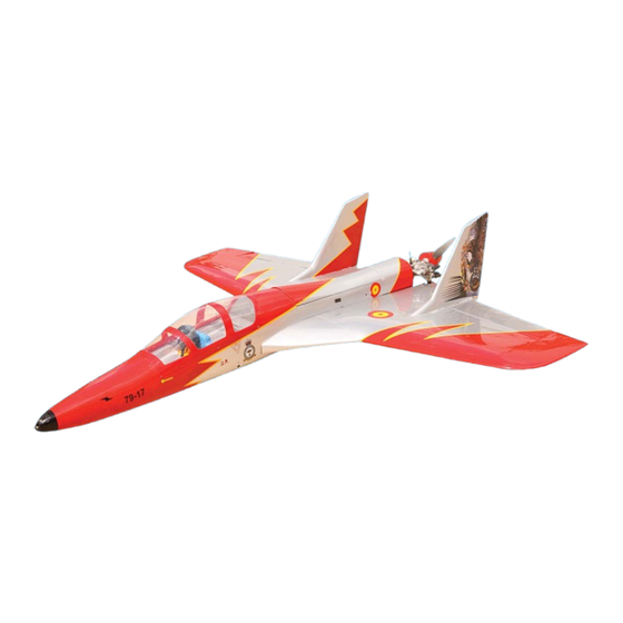
MS:159
ASSEMBLY MANUAL
"Graphics and specifications may change without notice".
Specifications:
Wing span ----------------------------61.8in (157cm).
Wing area -----------------1100.5sq.in (71.0sq dm).
Weight ----------------------- 6.6-7.5lbs (3.0-3.4kg).
Length ---------------------------------59.1in (150cm).
Engine --------------- 0.61-0.95cu.in ----2-stroke.
Radio --------------------6 channels with 6 servos.
Electric conversion :optional
Advertisement
Table of Contents

Related Manuals for Seagull Models ultra-jet


Summary of Contents for Seagull Models ultra-jet
- Page 1 MS:159 ASSEMBLY MANUAL “Graphics and specifications may change without notice”. Specifications: Wing span ----------------------------61.8in (157cm). Wing area -----------------1100.5sq.in (71.0sq dm). Weight ----------------------- 6.6-7.5lbs (3.0-3.4kg). Length ---------------------------------59.1in (150cm). Engine --------------- 0.61-0.95cu.in ----2-stroke. Radio --------------------6 channels with 6 servos. Electric conversion :optional...
-
Page 2: Kit Contents
ULTRA JET INTRODUCTION. Thank you for choosing the ULTRA JET ARTF by SEAGULL MODELS COMPANY LTD. The ULTRA JET was designed with the intermediate/advanced sport flyer in mind. It is a not semi scale airplane which is easy to fly and quick to assemble. The airframe is conventionally built using balsa, plywood to make it stronger than the average ARTF, yet the design allows the aeroplane to be kept light. - Page 3 www.seagullmodels.com KIT CONTENTS. INSTALL ELEVON CONTROL HORN. Fuselage Wing Set Fiberglass control horn Vertical Fins Canopy Leading Edge Extension Aluminum Wing Tube Hardware bag included ADDITIONAL ITEMS REQUIRED. 0.61-0.95 2-stroke. Computer radio with 6 servos. Glow plug to suit engine. Pusher propeller to suit engine.
-
Page 4: Instruction Manual
Instruction Manual. ULTRA JET Fill epoxy. 1) Attach the Leading Edge Extension to the wing. Use a hobby knife to remove the covering at the Leading Edge Extension and wing end. Fill epoxy. Remove covering. Remove covering. Seal covering iron. 2) Apply epoxy to the surface of the Wing and Leading Edge Extension and hole them together until the epoxy had set. -
Page 5: Engine Mount Installation
www.seagullmodels.com 2) Using a modeling knife, cut one length ENGINE MOUNT INSTALLATION. of silicon fuel line. Connect one end of the line 1) Locate the items necessary to install the to the weighted fuel pick up and the other end engine mount included with your model. -
Page 6: Fuel Tank Installation
Instruction Manual. ULTRA JET 4) Test fit the stopper assembly into the tank. It may be necessary to remove some of M3x10mm. the flashing around the tank opening using a modeling knife. If flashing is present, make sure none falls into the tank. 5) With the stopper assembly in place, the weighted pick-up should rest away from the rear of the tank and move freely inside the... -
Page 7: Installing The Switch
www.seagullmodels.com 2) Secure the servos with the screws pro- vided with your radio system. Throttle servo. Throttle servo arm. Steering servo arm. Steering servo. Retract servo arm. INSTALLING THE SWITCH. Retract servo. Install the switch into the precut hole in the side, in the fuselage. -
Page 8: Mounting The Engine
Instruction Manual. ULTRA JET 4.5mm. Switch. 4) On the fire wall has drill a hole in the firewall for the throttle pushrod the location for the MOUNTING THE ENGINE. throttle pusshrod tube (pre-drill). 1) Position the engine with the drive washer (130mm) forward of the firewall as shown. - Page 9 www.seagullmodels.com ELECTRIC POWER CONVERSION. 1) Locate the items neccessary to install the electric power conversion included with your model. Pushrod wire Recommendation EP parts as shown (not included with your model) 8) Reinstall the servo horn by sliding the - Model size: .61-75 size models connector over the pushrod wire.
- Page 10 Instruction Manual. ULTRA JET 4mm. Blind nut. M4x60mm. 3) Attach the motor to the front of the electric motor box using four 3mm blind nut, four M3x15mm hex head bolts to secure the motor. Please see picture shown. M3x15mm. Electric motor.
-
Page 11: Installing The Spinner
www.seagullmodels.com 4) Locate the plywood battery tray to the fuselage. Tighten the screws using machine screws M3x15mm to secure the tray in position. The propeller should not touch any part of the spinner cone. If it does, use a sharp modeling knife and carefully trim away the spinner cone where the propeller comes in contact with it. - Page 12 Instruction Manual. ULTRA JET 2) Install Pushrod. 70mm. M2 clevis. M2 lock nut. 2mm. M3 lock nut. M3 clevis. 2mm. Retract pushrod. 2mm Diameter Screw. Cable Steering. M3x15mm.
- Page 13 www.seagullmodels.com M3 clevis. Wheel collar. Screw. 3) Install Wheel. Axle. Landing gear. Axle. Screw. M2x10mm. Wheel collar. INSTALLING THE AILERON Axle. Wheel.
- Page 14 Instruction Manual. ULTRA JET Servos. Small weight. Thread. Because the size of servos differ, you may need to adjust the size of the precut open- 5) Use dental floss to secure the connection ing in the mount. The notch in the sides of so they cannot become unplugged.
- Page 15 www.seagullmodels.com String. Small weight. 9) Set the elevon hatch in place and use a Phillips screw driver to install it with four wood screws. ELEVON PUSHROD HORN INSTALLATION. 125mm. M3 clevis. M3 lock nut. 155mm.
- Page 16 Instruction Manual. ULTRA JET Elevon pushrod. M3 lock nut. 2mm Diameter Screw. INSTALLING RETRACTABLE LANDING GEAR . Screw. M3x15mm. Wheel Fairing. 2mm. Epoxy.
- Page 17 www.seagullmodels.com Wheel . Epoxy. Wheel Collar. Wheel Collar. Screw. Screw. RETRACTABLE LANDING GEAR PUSHROD INSTALLATION Wheel . 1) Locate items necessary to install landing gear pushrod .
- Page 18 Instruction Manual. ULTRA JET 30mm. M3 clevis. M3 lock nut. 50mm. Pushrod . ATTACHMENT TAIL - WING. M3x20mm.
- Page 19 www.seagullmodels.com 1) Attach the tail to the wing. Use a hobby knife to remove the covering at the tail and wing end. Remove covering. Fill epoxy. 3) With the tail held firmly in place, use a Remove covering. pen and draw lines onto the tail where it and the wing sides meet.
- Page 20 Please see pictures shown. 2) A scale pilot is included with this ARF. The Seagull Pilot included fitting well to the cockpit. (or you can order others scale pilot figures made by Seagull factory. They are available at Seagull distributors.)
- Page 21 www.seagullmodels.com Insert two wing panels as pictures below. C/A glue. C/A glue. M2x6mm. INSTALLING RECEIVER AND BATTERY. 1) Plug the five servo leads and the switch lead into the receiver. Plug the battery pack lead into the switch also. Wing bolt. 2) Wrap the receiver and battery pack in the protective foam rubber to protect them from vibration.
-
Page 22: Control Throws
Instruction Manual. ULTRA JET Lift the model. If the tail drops when you lift, 2) Mount the wing to the fuselage. Using a the model is “tail heavy” and you must add couple of pieces of masking tape, place them weight* to the nose. -
Page 23: Flight Preparation
www.seagullmodels.com FLIGHT PREPARATION. PREFLIGHT CHECK. Check the operation and direction of the 1) Completely charge your transmitter and receiver batteries before your first day of elevator, rudder, ailerons and throttle. flying. A) Plug in your radio system per the 2) Check every bolt and every glue joint manufacturer's instructions and turn every- in the ULTRA JET to ensure that thing on.
Need help?
Do you have a question about the ultra-jet and is the answer not in the manual?
Questions and answers