Table of Contents
Advertisement
Quick Links
A S S E M B L Y M A N U A L
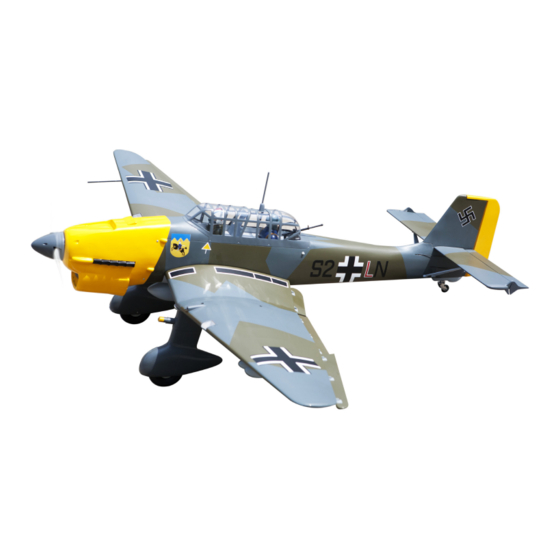
JU-87 STUKA GIANT SCALE
" Graphics and speciications may change without notice " .
Code: SEA284
Speciications:
Wingspan---------------90 in (228.6 cm).
Wing area---------------1328.7 sq.in (85.7 sq.dm).
Weight-------------------17.6 lbs (8.0 kg).
Length-------------------68.3 in (173.4 cm).
Gasoline Engine--------38-50cc
Radio--------------------7 channels with 7 servos.
1
www.modellmarkt24.ch
www.modellmarkt24.ch
Advertisement
Table of Contents

Subscribe to Our Youtube Channel
Related Manuals for Seagull Models JU-87 STUKA GIANT SCALE


Summary of Contents for Seagull Models JU-87 STUKA GIANT SCALE
- Page 1 A S S E M B L Y M A N U A L JU-87 STUKA GIANT SCALE “ Graphics and speciications may change without notice “ . Code: SEA284 Speciications: Wingspan---------------90 in (228.6 cm). Wing area---------------1328.7 sq.in (85.7 sq.dm).
-
Page 2: Kit Contents
JU-87 Instruction Manual. INTRODUCTION. hank you for choosing the JU-87 ARF by SG MODELS . he JU-87 was designed with the intermediate/advanced sport lyer in mind. It is a semi scale airplane which is easy to ly and quick to assemble. he airframe is conventionally built using balsa, ply- wood to make it stronger than the average ARF, yet the design allows the aeroplane to be kept light. -
Page 3: Hinging The Aileron
KIT CONTENTS. HINGING THE AILERON. SEA284 JU-87 STUKA GIANT 1. Fuselage 2. Wing set 3. Tail set 4. Canopy 5. Cowling 6. Pilot 7. Aluminum wing tube 8. Wheel pants ADDITIONAL ITEMS REQUIRED. � 38-50cc gasoline engine. � 2x10mm Computer radio with 7 servos. �... - Page 4 JU-87 Instruction Manual. HINGING THE FLAP. www.modellmarkt24.ch www.modellmarkt24.ch...
- Page 5 INSTALL THE AILERONS CONTROL HORN. Epoxy. Fiberglass control horn Flap control horn. Epoxy. Epoxy. Aileron control horn. INSTALL LED LIGHT. Epoxy. INSTALL FLAP CONTROL HORN. Install the lap control horn using the same method as same as the aileron con- trol horns.
- Page 6 JU-87 Instruction Manual. Epoxy. HINGING THE FLAP FOR CENTER WING. 1) Repeat steps to install hinging for center wing as same as steps done for ai- lerons. 3) Slide the wing tube into the wing tube socket. 2) hen, it the joiner wire into the lap of center wing as below pictures.
-
Page 7: Installing The Aileron Servos
4) Slide the wing panel into position, INSTALLING THE AILERON SERVOS. guiding the extensions from the side wing into center wing. Because the size of servos difer, you may need to adjust the size of the precut opening in the mount. he notch in the sides of the mount allow the servo lead to pass through. - Page 8 JU-87 Instruction Manual. 7) Apply 1-2 drops of thin C/A to each of 3) Use drill bit in a pin vise to drill the the mounting tabs. Allow the C/A to cure mouting holes in the blocks. without using accelerator. 4) Apply 2-3 drops of thin C/A to each of the mounting holes.
-
Page 9: Aileron Pushrod Installation
AILERON PUSHROD INSTALLATION. Please see below pictures. 100mm M3 lock nut. M3 clevis. 9) Set the aileron hatch in place and use a Phillips screw driver to install it with four wood screws. INSTALLING THE FLAP SERVO. 2x10mm Repeat the procedure as above for the lap servo. -
Page 10: Installing The Landing Gear
JU-87 Instruction Manual. INSTALLING THE LANDING GEAR. INSTALLING THE FLAP PUSHROD. Repeat the procedure as aileron push- rod. 100mm M3 lock nut. M3 clevis. www.modellmarkt24.ch www.modellmarkt24.ch... - Page 11 www.modellmarkt24.ch www.modellmarkt24.ch...
- Page 12 JU-87 Instruction Manual. 3x10mm www.modellmarkt24.ch www.modellmarkt24.ch...
- Page 13 3x10mm www.modellmarkt24.ch www.modellmarkt24.ch...
- Page 14 JU-87 Instruction Manual. INSTALLING THE BOMB ON THE WINGS. Epoxy. Epoxy. www.modellmarkt24.ch www.modellmarkt24.ch...
- Page 15 Epoxy. www.modellmarkt24.ch www.modellmarkt24.ch...
-
Page 16: Installing The Fuselage Servos
JU-87 Instruction Manual. THROTTLE SERVO ARM INSTALLATION. Epoxy. Install adjustable servo connector in the servo arm as same as picture below: Loctite secure. Adjustable servo connector. Servo arm. hrottle servo arm. INSTALLING THE FUSELAGE SERVOS. INSTALLING THE RECEIVER SWITCH. Because the size of servos difer, you may need to adjust the size of the precut Install the switch into the precut hole in opening in the mount. - Page 17 2) Using a modeling knife, cut one length of silicon fuel line. Connect one end of the line to the weighted fuel pick up and the other end to the nylon pick up tube. Switch. INSTALLING THE ENGINE SWITCH. Trim and cut. Vent tube.
-
Page 18: Fuel Tank Installation
JU-87 Instruction Manual. 6) When satisied with the alignment of the Vent tube. stopper assembly tighten the 3 x 20mm ma- chine screw until the rubber stopper expands and seals the tank opening. Do not over- tighten the assembly as this could cause the tank to split. - Page 19 Blind nut. 6.5 mm 5x100 mm 6.5 mm www.modellmarkt24.ch www.modellmarkt24.ch...
- Page 20 JU-87 Instruction Manual. 170mm 1) Reinstall the servo horn by sliding the connector over the pushrod wire. Center the throttle stick and trim and install the servo horn perpendicular to the servo center line. 2) Move the throttle stick to the closed po- sition and move the carburetor to closed.
- Page 21 ELECTRIC POWER CONVERSION. 1) Locate the items necessary to install 6.5mm the electric power conversion included with your model. 6.5mm 2) Recommend the items necessary to in- stall the electric power conversion parts included with your model. - Motor: 360 - 6000 Watt - Propeller: 24x10 ~ 25x12 - ESC: 160A- 200A - Lipo: 12S...
- Page 22 JU-87 Instruction Manual. M5x20mm M5x25mm 170mm Blind nut. 4) Attach the motor to the front of the electric motor box using four 4mm blind nut, four M5x20mm hex head bolts to se- cure the motor. Please see picture shown. 5) Attach the speed control to the side of the motor box using two-sided tape 6.5mm and tie wraps.
- Page 23 COWLING. 2) Use a drill and drill bit to drill the holes 1) Tape the cowl to the fuselage using for the cowl mounting screws. Make sure low-tack tape. the cowl position is correct before drill- ing each hole. www.modellmarkt24.ch www.modellmarkt24.ch...
- Page 24 JU-87 Instruction Manual. 3) Slide the muler screws through the engine. Place the mulr extension and gaskets included with the engine on the screws. Be careful when mounting the cowl so the screws and extension remain in position until the mulr can be at- tached.
-
Page 25: Installing The Spinner
INSTALLING THE SPINNER. he propeller should not touch any part of the spinner cone. If it does, use a sharp modeling knife and carefully trim away the spinner cone where the propel- ler comes in contact with it. Epoxy. Insert plastic cover on the cowling. HINGING THE ELEVATOR. -
Page 26: Hinging The Rudder
JU-87 Instruction Manual. INSTALL ELEVATOR CONTROL HORN. Fiberglass control horn. Epoxy. Epoxy. Elevator iberglass control horn. Epoxy. HINGING THE RUDDER. Glue the top three rudder hinges in place using the same techniques used to hinge the elevator. he lower hinge will be glued when the in/rudder assembly is attached to the fu- selage. -
Page 27: Installing The Horizontal Stabilizer
INSTALLING THE HORIZONTAL STABILIZER. 1) Using a ruler and a pen, locate the centerline of the horizontal stabilizer, at the trailing edge, and place a mark. Use a triangle and extend this mark, from back to front, across the top of the stabilizer. Also extend this mark down the back of the trailing edge of the stabilizer. -
Page 28: Installing Vertical Stabilizer
JU-87 Instruction Manual. 7) When you are sure that everything is 4) With the stabilizer held irmly in place, aligned correctly, mix up a generous use a pen and draw lines onto the stabi- amount of 30 Minute Epoxy. Apply a thin lizer where it and the fuselage sides meet. - Page 29 1) Using a modeling knife, remove the covering from over the precut hinge slot cut into the lower rear portion of the fu- selage. his slot accepts the lower rudder hinge. Epoxy. 4) Slide the vertical stabilizer back in- place. Using a triangle, check to ensure that the vertical stabilizer is aligned 90º...
-
Page 30: Elevator Pushrod Installation
JU-87 Instruction Manual. 4) Elevator and rudder pushrods assem- bly as pictures below. C/A glue. Hinge. ELEVATOR PUSHROD INSTALLATION. Elevator pushrod. 1) Install the elevator control horn using the same method as with the aileron con- trol horns. Cut. M2 clevis. M2 lock nut. -
Page 31: Mounting The Tail Wheel
MOUNTING THE TAIL WHEEL. Elevator pushrod. Rudder pushrod. 935mm M2 lock nut. M2 clevis. 860mm Elevator pushrod. M2 clevis. M2 lock nut. Rudder pushrod. www.modellmarkt24.ch www.modellmarkt24.ch... - Page 32 JU-87 Instruction Manual. Epoxy. TAIL STRUTS INSTALLATION. www.modellmarkt24.ch www.modellmarkt24.ch...
- Page 33 Epoxy. SIDE FORCE GENERATOR OF STABILIZER ASSEMBLY. Epoxy. www.modellmarkt24.ch www.modellmarkt24.ch...
- Page 34 JU-87 Instruction Manual. Epoxy. INSTALLATION PILOT AND CANOPY. 1) Locate items necessary to install pilot, seats. Epoxy. 2) Assembly gun as below steps. Epoxy. Epoxy. www.modellmarkt24.ch www.modellmarkt24.ch...
- Page 35 80mm 152mm 5) Drill hole on canopy. 3) A scale pilot is included with this ARF. he Pilot included itting well to the cockpit. (or you can order others scale pilot igures made by SG Models. hey are available at SG Models distributors.) If you are going to install a pilot igure, please use a sanding bar to sand the base of the igure so that it is lat.
-
Page 36: Apply The Decals
JU-87 Instruction Manual. 2x8mm APPLY THE DECALS. he decals are sticky-back type. Most are factory die-cut to shape. If you want to trim the edges closer, use a sharp #11 hobby knife. Small decals can be applied by simply removing the paper backing sheet, and then lay the decal in position. - Page 37 Battery. Receiver. ATTACHMENT WING- FUSELAGE. Wing bolt. 6x6mm www.modellmarkt24.ch www.modellmarkt24.ch...
- Page 38 JU-87 Instruction Manual. Epoxy. Epoxy. ADJUSTMENT AILERON. Final step and also really necessary is adjust aileron. Please do it as shown. www.modellmarkt24.ch www.modellmarkt24.ch...
- Page 39 Accurately mark the balance point on the top of the wing on both sides of the fuselage. he balance point is located 130mm back from the leading edge of the wing at the wing root. his is the bal- ance point at which your model should balance for your irst lights.
-
Page 40: Control Throws
JU-87 Instruction Manual. CONTROL THROWS. Rudder: Ailerons: 130mm High Rate : High Rate : Up : 18mm Right : 30mm Down : 18mm Let : 30mm Low Rate : Low Rate : Right : 25mm Up : 13mm Down : 13mm Let : 25mm Elevator: Flap:... -
Page 41: Flight Preparation
FLIGHT PREPARATION. PREFLIGHT CHECK. 1) Completely charge your trans- Check the operation and direction mitter and receiver batteries before of the elevator, rudder, ailerons and your irst day of lying. throttle. 2) Check every bolt and every glue A) Plug in your radio system per the joint in the JU-87 to ensure that eve- manufacturer’s instructions and turn rything is tight and well bonded. - Page 42 JU-87 Instruction Manual. If you have any queries, or are interested in our products, please feel free to contact us Factory : 12/101A - Hamlet 4 - Le Van Khuong Street - Dong hanh Ward - Hoc Mon District - Ho Chi Minh City - Viet Nam. Oice : 62/8 Ngo Tat To Street - Ward 19 - Binh hanh District - Ho Chi Minh City - Viet Nam Phone : 848 - 37114542 or 848- 36018777...
Need help?
Do you have a question about the JU-87 STUKA GIANT SCALE and is the answer not in the manual?
Questions and answers