Table of Contents
Advertisement
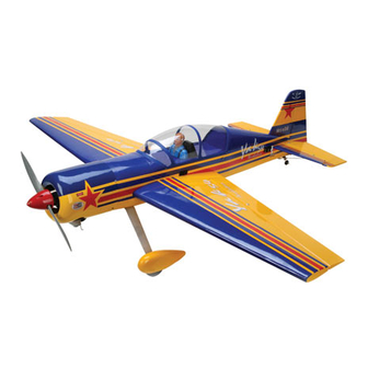
Specifications
Wingspan-------------------------------- 63.4 in --------------------- 161cm.
Wing area-------------------------------- 846 sq.in ----------- 54.6 sq.dm.
Weight------------------------------------- 8.4-9.9lbs -------------3.8-4.5kg.
Length------------------------------------- 61.4 in -------------------- 156cm.
Recommended engine size-------- .91-1.25 cu.in -------- 2-4stroke.
Radio System required 6 channel with 6 digital servos.
Flying skill level __ Intermediate/advanced.
Kit features.
•
Ready-made—minimal assembly & finishing required.
•
Ready-covered covering.
•
Photo-illustrated step-by-step Assembly Manual.
Made in Vietnam.
ASSEMBLY MANUAL
Advertisement
Table of Contents

Related Manuals for Seagull Models SEA53A_1 YAK 54


Summary of Contents for Seagull Models SEA53A_1 YAK 54
-
Page 1: Specifications
ASSEMBLY MANUAL Specifications Wingspan-------------------------------- 63.4 in --------------------- 161cm. Wing area-------------------------------- 846 sq.in ----------- 54.6 sq.dm. Weight------------------------------------- 8.4-9.9lbs -------------3.8-4.5kg. Length------------------------------------- 61.4 in -------------------- 156cm. Recommended engine size-------- .91-1.25 cu.in -------- 2-4stroke. Radio System required 6 channel with 6 digital servos. Flying skill level __ Intermediate/advanced. Kit features. -
Page 2: Fuselage Assembly
Instruction Manual. INTRODUCTION. Thank you for choosing the YAK 54 ARTF by SEAGULL MODELS. The YAK 54 was designed with the intermediate/advanced sport flyer in mind. It is a semi scale airplane which is easy to fly and quick to assemble. The airframe is conventionally built using balsa, plywood to make it stronger than the average ARTF , yet the design allows the aeroplane to be kept light. - Page 3 www.seagullmodels.com NOTE: To avoid scratching your new aero- plane we suggest that you cover your workbench with an old towel. Keep a couple of jars or bowls handy to hold the small parts after you open the bags. Please trial fit all parts. Make sure you have the correct parts and that they fit and are aligned properly before gluing! This will ensure proper as-...
-
Page 4: Hinging The Ailerons
YAK 54. Instruction Manual. HINGING THE AILERONS. T-pin. Note: The control surfaces, including the ailerons, elevators, and rudder, are prehinged with hinges installed, but the hinges are not glued in place. It is imperative that you properly adhere the hinges in place per the steps that follow using a high-quality thin C/A glue. -
Page 5: Hinging The Rudder
www.seagullmodels.com HINGING THE RUDDER. Glue the rudder hinges in place using the same tectniques used to hinge the ailerons. C/A glue. ! 6) Using C/A remover/debonder and a paper towel, remove any excess C/A glue that may have accumulated on the wing or in the aileron hinge area. -
Page 6: Engine Mount
YAK 54. Instruction Manual. Wing bottom. Thread. Small weight. Attach the string to the servo lead and carefully thread it though the wing. Once you have thread the lead throught the wing, remove Wing panel the string so it can use for the other servo bottom. -
Page 7: Installing The Stopper Assembly
www.seagullmodels.com Fuel Pick-up Tube. Vent tube. FUEL TANK. Fuel Fill Tube. INSTALLING THE STOPPER ASSEMBLY. Carefully use a lighter or heat gun to permenently set the angle of the vent tube. ! 1) Using a modeling knife, carefully cut off the rear portion of one of the 3 nylon tubes Important: When the stopper assembly is leaving 1/2”... -
Page 8: Elevator Servo Installation
YAK 54. Instruction Manual. Engine 1.25 - 4 stroke. You should mark which tube is the vent Servo tray. and which is the fuel pickup when you attach fuel tubing to the tubes in the stopper. Once the tank is installed inside the fuselage, it may C/A glue. -
Page 9: Horizontal Stabilizer
www.seagullmodels.com ! 3) Secure the servos with the screws pro- vided with your radio system. Right side. Switch. Elevator servo. HORIZONTAL STABILIZER. Left side. !1) Using a ruler and a pen, locate the centerline of the horizontal stabilizer, at the trail- ing edge, and place a mark. -
Page 10: Vertical Stabilizer Installation
YAK 54. Instruction Manual. ! 8) After the epoxy has fully cured, re- move the masking tape or T-pins used to hold the stabilizer in place. Carefully inspect the glue joints. Use more epoxy to fill in any gaps that may exist that were not filled previously Pen. - Page 11 www.seagullmodels.com ! 2) Slide the vertical stabilizer into the slot When cutting through the covering to re- in the top of the fuselage. The rear edge of move it, cut with only enough pressure to only the stabilizer should be flush with the rear edge cut through the covering itself.
-
Page 12: Aileron Control Horn Installation
YAK 54. Instruction Manual. ELEVATOR CONTROL HORN INSTALLATION. AILERON CONTROL HORN INSTALLATION 1) Elevator control horn: 2 sets. Mix a small amount of 30 minute epoxy and lightly coat the inside of the hole in the elevator and the 3x40mm control horn screw. Horizontal fin. -
Page 13: Aileron Pushrod Installation
www.seagullmodels.com 3x30mm. Center the servo using the radio system. Attach the servo arm to the servo using the screw provided with the servo. 2x20mm. Elevator pushrod. Rudder control horn. ! 3) Position the rudder horn on the both Repeat the procedure for orther side of rudder. - Page 14 YAK 54. Instruction Manual. RUDDER PULL - PULL CABLE SYSTEM. Pushrod. See pictures below: Control horn. Cable. Metal clevis. M3 lock nut. ! 1) Insert servo arm into servo. WHEEL AND WHEEL PANTS. ! 2) With the radio on, check the operation of the rudder.
- Page 15 www.seagullmodels.com Plywood Washer. Wheel Collar. Axle. Nut. Nut. Wheel. Landing Gear. Wheel Pant. Plywood Washer. 7mm. 14mm. ! 3) You have to trim each axles and using a lite-plywood block. tool cutting and cut-off wheel. Caution when cutting the axles wear protective goggles.
-
Page 16: Installing The Main Landing Gear
YAK 54. Instruction Manual. 140mm. INSTALLING THE MAIN LANDING GEAR. !1) The blind nuts for securing the landing gear are already mounted inside the fuselage. !2) Using the hardware provided, mount the 4.2mm. main landing gear to the fuselage. 5) Bolt the engine to the engine mount using the four machine screws. - Page 17 www.seagullmodels.com Mark point. Paper tape guide. Pushrod wire. Engine 1.25 - 4 stroke. 1mm drill bit. Paper tape guide. 4x30mm. Pushrod wire. Mark point. COWLING. Trim and cut. ! 1) Slide the fiberglass cowl over the en- gine and line up the back edge of the cowl with the marks you made on the fuselage then trim and cut.
-
Page 18: Installing The Spinner
YAK 54. Instruction Manual. 3x10mm. INSTALLING THE SPINNER. Because of the size of the cowl, it may be necessary to use a needle valve exten- Install the spinner backplate, propeller and sion for the high speed needle valve. Make spinner cone. this out of sufficient length 1.5mm wire and in- stall it into the end of the needle valve. -
Page 19: Mounting The Tail Wheel
www.seagullmodels.com 62cm. Aluminium 3x10mm. strap. MOUNTING THE TAIL WHEEL. 33mm. Plastic clip. ! 1) You have to trim each axles and using a tool cutting and cut-off wheel. Caution when cutting the axles wear protective goggles. - Page 20 YAK 54. Instruction Manual. 3x25mm. ! 2) Set the tail wheel assembly in place. The pivot point of the tail wheel wire should be even with the rudder hinge line and the tail wheel bracket should be on the plywood THROTTLE SERVO ARM plate.
- Page 21 www.seagullmodels.com Antenna wire. Throttle. Antenna. ATTACHMENT WING-FUSELAGE. Attach the aluminium tube into fuselage. INSTALLING THE BATTERY-RECEIVER. ! 1) Plug the six servo leads and the switch lead into the receiver. Plug the battery pack lead into the switch also. 2) Wrap the receiver and battery pack in the protective foam rubber to protect them from vibration.
-
Page 22: Control Throws
YAK 54. Instruction Manual. sides under the horizontal stabilizer. If the tail of the plane falls, the plane is tail heavy. To correct this, move the battery and receiver for- ward orif this is not possible, stick weight onto the firewall or use a brass heavy hub spinner hub, similar to those offered by Harry Higley. -
Page 23: Flight Preparation
www.seagullmodels.com PREFLIGHT CHECK. FLIGHT PREPARATION. ! A) Check the operation and direction of !1) Completely charge your transmitter the elevator, rudder, ailerons and throttle. and receiver batteries before your first day of flying. ! B) Plug in your radio system per the !2) Check every bolt and every glue joint manufacturer's instructions and turn every- in the YAK 54 to ensure that everything is tight...
Need help?
Do you have a question about the SEA53A_1 YAK 54 and is the answer not in the manual?
Questions and answers