Table of Contents
Advertisement
Quick Links
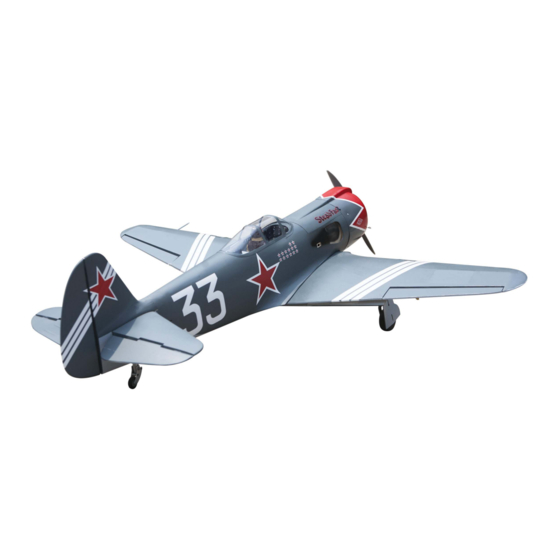
YAKOVLEV YAK 3
" Graphics and speciications may change without notice ".
A S S E M B L Y M A N U A L
- 63 inch
Speciications:
Wingspan---------------63.0 in (160 cm).
Wing area---------------723.9 sq.in ( 46.7sq.dm).
Weight-------------------11.5 lbs ( 5.2 kg).
Length-------------------55.4 in (140.6 cm).
Engine-------------------20cc
Radio--------------------7 channels with 7 servos.
Code: SEA270
1
Advertisement
Table of Contents

Subscribe to Our Youtube Channel
Related Manuals for Seagull Models YAKOVLEV YAK 3


Summary of Contents for Seagull Models YAKOVLEV YAK 3
- Page 1 A S S E M B L Y M A N U A L YAKOVLEV YAK 3 - 63 inch “ Graphics and speciications may change without notice ”. Code: SEA270 Speciications: Wingspan---------------63.0 in (160 cm). Wing area---------------723.9 sq.in ( 46.7sq.dm).
-
Page 2: Kit Contents
YAK 3 Instruction Manual. INTRODUCTION. hank you for choosing the YAK 3 ARF by SG MODELS. he YAK 3 was designed with the intermediate/advanced sport lyer in mind. It is a semi scale airplane which is easy to ly and quick to assemble. he airframe is conventionally built using balsa, plywood to make it stronger than the average ARF, yet the design allows the aeroplane to be kept light. -
Page 3: Additional Items Required
HINGING THE FLAP. KIT CONTENTS. SEA270 YAK 3 1. Fuselage 2. Wing set 3. Tail set 2x10mm. 4. Canopy 5. Cowling 6. Pilot ADDITIONAL ITEMS REQUIRED. � 20cc gasoline engine. � Computer radio with 9 servos. � Glow plug to suit engine. �... -
Page 4: Hinging The Aileron
YAK 3 Instruction Manual. 4) Delect the aileron and completely satu- HINGING THE AILERON. rate each hinge with thin C/A glue. he ailer- ons front surface should lightly contact the Note : he control surfaces, including the ai- wing during this procedure. Ideally, when lerons, elevators, and rudder, are prehinged the hinges are glued in place, a 1/64”... - Page 5 8) Ater both ailerons are securely hinged, irmly grasp the wing panel and aileron to make sure the hinges are securely glued and cannot be pulled out. Do this by carefully ap- plying medium pressure, trying to separate the aileron from the wing panel. Use caution not to crush the wing structure.
-
Page 6: Installing The Aileron Servos
YAK 3 Instruction Manual. WING ASSEMBLY. Please see below pictures. INSTALLING THE AILERON SERVOS. Attach the aluminum tube into wing. Because the size of servos difer, you may need to adjust the size of the precut opening in the mount. he notch in the sides of the mount allow the servo lead to pass through. - Page 7 7) Apply 1-2 drops of thin C/A to each of the mounting tabs. Allow the C/A to cure without using accelerator. 3) Use drill bit in a pin vise to drill the mouting holes in the blocks. C/A glue. 8) Remove the string from the wing at the servo location and use the tape to at- 4) Apply 2-3 drops of thin C/A to each of the mounting holes.
-
Page 8: Aileron Pushrod Installation
YAK 3 Instruction Manual. INSTALLING THE FLAP SERVO. Repeat the procedure for the lap servo. AILERON PUSHROD INSTALLATION. Please see below pictures. 9) Set the aileron hatch in place and use a Phillips screw driver to install it with four wood screws. -
Page 9: Light Cover
LIGHT COVER. Bend at the mark M2 lock nut. Metal clevis. Snap keeper. Servo arm. Snap keeper. Nylon Snap keeper. Hex Nut. Fuel tubing. INSTALLING THE FLAP PUSHROD. INSTALLING RETRACTABLE LANDING GEAR. Repeat the procedure for the aileron Locate items necessary to install Sprin pushrod. - Page 10 YAK 3 Instruction Manual. 3x20mm.
- Page 11 Collar. M3x4mm.
- Page 12 YAK 3 Instruction Manual. 3x10mm.
-
Page 13: Installing The Fuselage Servos
INSTALLING THE FUSELAGE SERVOS. INSTALLING THE RECEIVER SWITCH. Because the size of servos difer, you Install the switch into the precut hole in may need to adjust the size of the precut the side, in the fuselage. opening in the mount. he notch in the sides of the mount allow the servo lead to 3/32”... -
Page 14: Installing The Stopper Assembly
YAK 3 Instruction Manual. Switch. Vent tube. Fuel pick up tube. INSTALLING THE STOPPER ASSEMBLY. Fuel fill tube. 1) Using a modeling knife, carefully cut 3) Carefully bend the second nylon tube up of the rear portion of one of the 3 nylon at a 45º... -
Page 15: Engine Mount Installation
7) Slide the fuel tank into the fuselage. Guide 8) Connect the lines from the tank to the en- the lines from the tank through the hole in gine and muler. he vent line will connect the irewall. to the muler and the line from the clunk to the carburetor. -
Page 16: Mounting The Engine
YAK 3 Instruction Manual. MOUNTING THE ENGINE. 1) Position the engine with the drive washer (145mm) forward of the irewall as shown. Machine screw M4x30mm 4) On the ire wall has the location for the throttle pusshrod tube (pre-drill). 5) Slide the pushrod tube in the irewall and guide it through the fuel tank mount. - Page 17 COWLING. Please see below pictures. HINH XUA 8) Reinstall the servo horn by sliding the connector over the pushrod wire. Cent- er the throttle stick and trim and install the servo horn perpendiular to the servo center line. Cut. 9) Move the throttle stick to the closed po- sition and move the carburetor to closed.
- Page 18 YAK 3 Instruction Manual. Because of the size of the cowl, it may be nec- essary to use a needle valve extension for the high speed needle valve. Make this out of suf- icient length 1.5mm wire and install it into the end of the needle valve.
- Page 19 - Motor: 110 -2000 Watt 4 mm - Propeller: 17x 8 ~ 19x10 - ESC: 85A - Lipo Batteries: 8S - 9S 3) Attach the electric motor box to the irewall suitable with the cross lines drawn on the electric motor box and ire- wall.
-
Page 20: Installing The Spinner
YAK 3 Instruction Manual. Epoxy Battery. 145mm Balsa stick. Open the air exit hole. Epoxy 6) Attach the speed control to the side of the motor box using two-sided tape and tie wraps. Connect the appropriate leads from the speed control to the mo- tor. -
Page 21: Hinging The Elevator
Elevator iberglass control horn. Epoxy. INSTALLING THE HORIZONTAL HINGING THE ELEVATOR. STABILIZER. Glue the elevator hinges in place using 1) Using a ruler and a pen, locate the cen- the same techniques used to hinge the ai- terline of the horizontal stabilizer, at the lerons. -
Page 22: Hinging The Rudder
YAK 3 Instruction Manual. Epoxy 7) When you are sure that everything is aligned correctly, mix up a generous 4) With the stabilizer held irmly in place, amount of 30 Minute Epoxy. Apply a thin use a pen and draw lines onto the stabi- layer to the top and bottom of the stabi- lizer where it and the fuselage sides meet. -
Page 23: Installing Vertical Stabilizer
INSTALLING VERTICAL STABILIZER INSTALL RUDDER CONTROL HORN. 1) Using a modeling knife, remove the Repeat steps to install the rudder con- covering from over the precut hinge slot trol horn as same as steps done for ailer- cut into the lower rear portion of the fu- selage. -
Page 24: Elevator Pushrod Installation
YAK 3 Instruction Manual. 5) When you are sure that everything is aligned correctly, mix up a generous amount of Flash 30 Minute Epoxy. Ap- ply a thin layer to the mounting slot and to bottom of the vertical stabilizer mounting area. -
Page 25: Rudder Pushrod Installation
3) hread one clevis and M2 lock nut on to each elevator control rod. hread the horns on until they are lush with the ends of the control rods. 4) Elevator and rudder pushrods assem- bly as pictures below. Elevator pushrod. M2 clevis. -
Page 26: Mounting The Tail Wheel
YAK 3 Instruction Manual. MOUNTING THE TAIL WHEEL. Pen. - Page 28 YAK 3 Instruction Manual. PLASTIC PARTS WITH PANEL INSTRUCTIONS.
- Page 29 INSTALLATION PILOT AND CANOPY. 1) Locate items necessary to install pilot, seats.
- Page 30 YAK 3 Instruction Manual. 4) Position the canopy onto the fuselage. Trace around the canopy and onto the fu- selage using a felt-tipped pen. Carefully cut and remove covering material from the fuselage where the canopy makes contact, exposing the bare wood. hen permanently glue the canopy in place with epoxy glue or special “canopy glue”.
- Page 31 Battery. Wing bolt. Receiver. Battery. ATTACHMENT WING- FUSELAGE. hen, install wing guns on the wings.
- Page 32 YAK 3 Instruction Manual. Accurately mark the balance point on the top of the wing on both sides of the fuselage. he balance point is located 160mm back from the leading edge of the wing at the wing root. his is the bal- Epoxy ance point at which your model should balance for your irst lights.
-
Page 33: Control Throws
CONTROL THROWS. Ailerons: 160mm High Rate : 15mm Low Rate 12mm Elevator: High Rate : 15mm Low Rate 12 mm Rudder: High Rate : 25mm Low Rate 20 mm... -
Page 34: Flight Preparation
YAK 3 Instruction Manual. FLIGHT PREPARATION. PREFLIGHT CHECK. Check the operation and direction 1) Completely charge your trans- of the elevator, rudder, ailerons and mitter and receiver batteries before throttle. your irst day of lying. A) Plug in your radio system per the 2) Check every bolt and every glue manufacturer’s instructions and turn joint in the YAK 3 to ensure that eve-... - Page 35 If you have any queries, or are interested in our products, please feel free to contact us Factory : 12/101A - Hamlet 4 - Le Van Khuong Street - Dong hanh Ward - Hoc Mon District - Ho Chi Minh City - Viet Nam. Oice : 62/8 Ngo Tat To Street - Ward 19 - Binh hanh District - Ho Chi Minh City - Viet Nam Phone : 848 - 37114542 or 848- 36018777...
Need help?
Do you have a question about the YAKOVLEV YAK 3 and is the answer not in the manual?
Questions and answers