Table of Contents
Advertisement
Advertisement
Table of Contents

Summary of Contents for socomec Asys 16 A Transfer System
- Page 1 INSTALLATION AND OPERATING MANUAL ASYS 16 A Transfer System IOMASY160810-GB_00...
-
Page 3: Intended Use
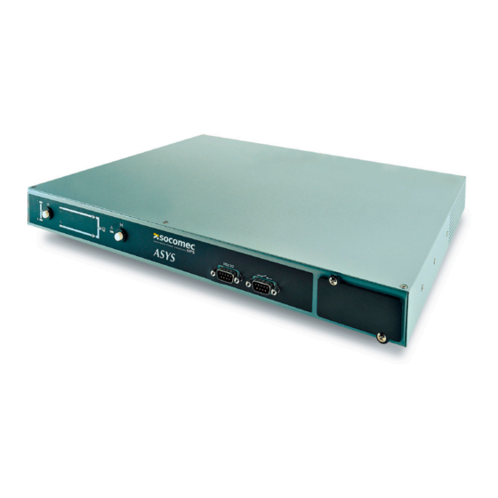
ASYS 16 A Transfer System INTENDED USE The ASYS TRANSFER SWITCH device is used as a power source selector providing a redundant power supply to the load. It runs on a single phase network. The device is compliant with all relevant safety regulations concerning information technology equipment, including electronic equipment for use in an office environment. -
Page 5: Technical Data
ASYS 16 A Transfer System AblE Of CONTENTS 1. C ERTIfICATE AND CONDITIONS Of WARRANTy 2. S AfETy 2. 1. I mpORTANT 2. 2. E mERGENCy 2. 3. p ACkAGING 2. 4. W ARNING 3. O VERVIEW 3. 1. p ASyS TRANSfER SWITCH URpOSE Of 4. - Page 6 The warranty conditions are stipulated in the sales contract. If not the following points shall apply: SOCOMEC’s guarantee is strictly limited to the product(s) and does apply neither to the equipment in which they could be integrated nor to the performance of such equipment.
- Page 7 ASYS 16 A Transfer System AfETy 2. 1. mpORTANT Read the following safety notices carefully! Failure to observe the instructions may en- danger your life, your health, the reliability of your device or the security of your data. – Transport the unit only in its original packaging. –...
- Page 8 ASYS 16 A Transfer System 2. 3. ACkAGING All packaging material must be recycled in compliance with the laws in force in the country where the system is installed. 2. 4. ARNING – It is absolutely necessary to earth the ASYS before connecting any upstream and downstream supplies.
-
Page 9: Unpacking And Installation
ASYS 16 A Transfer System VERVIEW ASyS TRANSfER SWITCH 3. 1. URpOSE Of The 2-pole ASYS is a two-way, single phase automatic switch powered by two inde- pendent synchronous or asynchronous AC power supply sources. ASYS provides redundant power, it makes a rapid switch from one source to the oth- er in the event of a fault to the power supply used to power the load. -
Page 10: Environmental Conditions
ASYS 16 A Transfer System 4. 3. TORAGE Storage temperature: -25 to 70°C, Storage humidity: from 10% to 90%. 4. 4. ANDlING The equipment must be handled with care. Damage may be caused if dropped or subjected to severe impacts. 4. -
Page 11: Rear Panel
ASYS 16 A Transfer System 4. 7. NVIRONmENTAl REqUISITES It is necessary to leave a minimum space of a few centimetres around right side, left side and rear side to allow a flow of air and to provide access to the interface. RESENTATION 5. - Page 12 ASYS 16 A Transfer System 5. 3. pERATING ANEl On the following scheme you can see the front panel of the ASYS. Most functions of the ASYS are driven by an internal control device. A priority setting can be made from the operating panel to prefer a mains source. LEDs display the state of the relay group.
-
Page 13: Operating Procedures
ASYS 16 A Transfer System pERATING pROCEDURES ASYS TRANSFER SWITCH panel display LED 1 and LED 2 = Preferred Source indication: Green LEDs indicate witch Input Source is selected as the preferred LEFT BUTTON = change the Preferred Source: source 1 is the preferred source on the factory setting, the modification of the preferred source is done by pressing for 3 seconds on this button LED input line = status of the input source... - Page 14 ASYS 16 A Transfer System ON p 6. 1. ANUAl WITCH ROCEDURES First Switch on from Source 1 – Check that all switches are OFF – Input the mains for source 1. – Wait a few seconds until the logic is enabled and the LEDs on the display are switched ON.
- Page 15 ASYS 16 A Transfer System ECHNICAl 7. 1. NpUT UTpUT fEATURES ASYS 16A-120 ASYS 16A-230 INPUT Nominal voltages 120V 220/230/240V selectable Nominal +/- 12%* to +/- 20% adjustable** Voltage acceptance window Working range voltage 80 ~ 145Vac 160 ~ 290Vac 50/60 Hz auto sensing Nominal frequency acceptance +/- 15%...
-
Page 16: Specifications
ASYS 16 A Transfer System 7. 3. OmmUNICATIONS Dry Contact (DB-9, pin type) PIN N°. Definition PIN 4 Input Mains 1 (OK / NG) PIN 8 Input Mains 2 (OK / NG) PIN 1 Over Temperature PIN 7 Overload PIN 9 SUM Alarm PIN 5 Common... -
Page 17: Safety Standards
ASYS 16 A Transfer System 7. 6. AfETy TANDARDS EN62310-1. (With CE Mark) EmC S 7. 7. TANDARD IEC62310-2, C1 IEC61000-4-2 level 3 IEC61000-4-3 level 2 (Lab.) IEC61000-4-4 level 2 IEC61000-4-5 level 3 IEC 61000-2-2 LF Immunity IEC61000-4-6 level 2 (Lab.) IEC61000-3-2 Harmonic (Lab.) IEC61000-3-3 Flicks * * For ASYS 16A-230 only. - Page 18 ASYS 16 A Transfer System 7. 9. xTERNAl ROTECTION AND SOlATION EVICES External protection devices need to be installed upstream and downstream of the equipment to protect the cables and the unit. Upstream these devices need to be selected and configured with the size of the unit in mind. Disconnection devices must always be provided All protection devices (circuit breakers and fuses) installed upstream of the unit need to be co-ordinated for discrimination with the ASYS input protection (fuses) and the...
-
Page 19: Troubleshooting
ASYS 16 A Transfer System ROUblESHOOTING If problems should occur, please check the following points before contacting the customer service department: – Is the mains voltage present at the ASYS TRANSFER SWITCH input? – Has one of the two input fuses tripped or open? If you contact the customer service department, please have the following informa- tion ready: –...


Need help?
Do you have a question about the Asys 16 A Transfer System and is the answer not in the manual?
Questions and answers