Lexmark X651de Service Manual
Hide thumbs
Also See for X651de:
- Service manual (653 pages) ,
- Troubleshooting manual (13 pages) ,
- Quick reference manual (9 pages)
Table of Contents
Advertisement
Quick Links
Lexmark
X656dte, X658d, X658de, X658dme, X658dfe,
X658dte, X658dtme, X658dtfe
• Table of contents
• Start diagnostics
• Safety and notices
• Trademarks
• Index
Revision: February 28, 2012
™
X651de, X652de, X654de, X656de,
Machine Type 7462
Lexmark and Lexmark with diamond design are
trademarks of Lexmark International, Inc., registered
in the United States and/or other countries.
Advertisement
Table of Contents
Troubleshooting

Related Manuals for Lexmark X651de


Summary of Contents for Lexmark X651de
- Page 1 X658dte, X658dtme, X658dtfe Machine Type 7462 • Table of contents • Start diagnostics • Safety and notices • Trademarks • Index Lexmark and Lexmark with diamond design are trademarks of Lexmark International, Inc., registered in the United States and/or other countries.
- Page 2 Lexmark, Lexmark with diamond design, and MarkNet are trademarks of Lexmark International, Inc., registered in the United States and/or other countries. Optra Forms is a trademark of Lexmark International, Inc.
-
Page 3: Table Of Contents
7462 Table of contents Previous Table of contents ............iii Notices and safety information . - Page 4 7462 Media missing jam service check ..........2-122 Previous Sensor (ADF media exit) static jam service check .
- Page 5 7462 Network service check ............2-182 Previous Diagnostic aids .
- Page 6 7462 Auto Dark Adjust ............3-25 Previous REPORTS .
- Page 7 7462 Media tray assembly ............3-46 Previous Detection of media size .
- Page 8 7462 Auto density sensing ............3-67 Previous Document scanning at ADF .
- Page 9 7462 Understanding jam numbers and locations ......... 3-83 Previous 200 and 203 paper jams .
- Page 10 7462 MPF pick solenoid assembly removal ..........4-26 Previous Pick arm assembly removal .
- Page 11 7462 Switch (ADF closed interlock) removal ..........4-79 Previous ADF unit assembly removal (models X651, X652, X654 and X656) .
- Page 12 7462 Scanner support cover, left front removal (model X658) ......4-147 Previous Scanner support cover, left removal (model X658) .
- Page 13 7462 MFP stapler assembly media stack flap and media stack flap actuator removal ..4-205 Previous MFP stapler assembly stapler unit assembly removal ....... 4-207 Stapler/stacker controller card assembly removal .
- Page 14 7462 Scheduled maintenance ............. . .6-2 Previous Maintenance kit .
-
Page 15: Notices And Safety Information
7462 Notices and safety information Previous The following laser notice labels may be affixed to this printer. Next Laser notice Go Back The printer is certified in the U.S. to conform to the requirements of DHHS 21 CFR Subchapter J for Class I (1) laser products, and elsewhere is certified as a Class I laser product conforming to the requirements of IEC 60825-1. - Page 16 7462 Previous Avisos sobre el láser Se certifica que, en los EE.UU., esta impresora cumple los requisitos para los productos láser de Clase I (1) establecidos en el subcapítulo J de la norma CFR 21 del DHHS (Departamento de Sanidad y Servicios) y, en los demás países, reúne todas las condiciones expuestas en la norma IEC 60825-1 para productos láser de Next Clase I (1).
- Page 17 7462 Previous Laserilmoitus Tämä tulostin on sertifioitu Yhdysvalloissa DHHS 21 CFR Subchapter J -standardin mukaiseksi luokan I (1) - lasertuotteeksi ja muualla IEC 60825-1 -standardin mukaiseksi luokan I lasertuotteeksi. Next Luokan I lasertuotteita ei pidetä haitallisina. Tulostimen sisällä on luokan IIIb (3b) laser, joka on nimellisteholtaan 5 mW:n galliumarsenidilaser ja toimii 770 - 795 nanometrin aallonpituuksilla.
- Page 18 7462 Previous Avís sobre el Làser Segons ha estat certificat als Estats Units, aquesta impressora compleix els requisits de DHHS 21 CFR, apartat J, pels productes làser de classe I (1), i segons ha estat certificat en altres llocs, és un producte làser de classe I que compleix els requisits d’IEC 60825-1.
- Page 19 7462 Previous Next Go Back Notices and safety information...
- Page 20 7462 Previous Next Go Back Service Manual...
-
Page 21: Lithium Warning
7462 Previous Lithium warning CAUTION This product contains a lithium battery. THERE IS A RISK OF EXPLOSION IF THE BATTERY Next IS REPLACED BY AN INCORRECT TYPE. Discard used batteries according to the battery manufacturer’s instructions and local regulations. Go Back Safety information The safety of this product is based on testing and approvals of the original design and specific •... - Page 22 7462 Previous Sicherheitshinweise • Die Sicherheit dieses Produkts basiert auf Tests und Zulassungen des ursprünglichen Modells und bestimmter Bauteile. Bei Verwendung nicht genehmigter Ersatzteile wird vom Hersteller keine Verantwortung oder Haftung für die Sicherheit übernommen. Next Die Wartungsinformationen für dieses Produkt sind ausschließlich für die Verwendung durch einen •...
- Page 23 7462 Previous Informació de Seguretat • La seguretat d'aquest producte es basa en l'avaluació i aprovació del disseny original i els components específics. El fabricant no es fa responsable de les qüestions de Next seguretat si s'utilitzen peces de recanvi no autoritzades. •...
-
Page 24: Go Back
7462 Preface Previous This manual contains maintenance procedures for service personnel. It is divided into the following chapters: General information contains a general description of the printer and the maintenance approach used to Next repair it. Special tools and test equipment, as well as general environmental and safety instructions, are discussed. -
Page 25: Change History
7462 Previous Change history Revision date Updates 2012/02/28 Added error code “917.00” on page 2-80. Next 2012/02/02 • Added PN 40X6932for the tray size sensing actuators in the following assemblies: “Pick arm and media tray assemblies” on page 7-11 “550 Sheet option tray assembly (X658)” on page 7-31 Go Back “250 Sheet option tray assembly (X651, X652, X654, and X656)”... -
Page 26: Conventions
7462 Previous Conventions Note: A note provides additional information. Warning: A warning identifies something that might damage the product hardware or software. Next There are several types of caution statements: CAUTION Go Back A caution identifies something that might cause a servicer harm. CAUTION This type of caution indicates there is a danger from hazardous voltage in the area of the product where you are working. -
Page 27: General Information
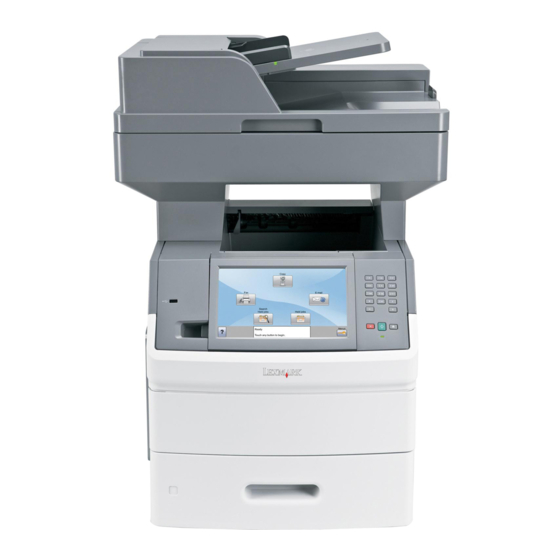
1. General information Previous The Lexmark™ X651, X652, X654, X656 and X658 are All-In-One laser MFPs that provide print, copy, scan, and fax functions designed to attach to most computer networks. The operator panel is touch-sensitive and allows the user to adjust the viewing angle. All information in this service manual pertains to all models unless Next explicitly noted. -
Page 28: Printer Overview
Floor-mounted configurations require additional furniture for stability. You must use either a printer stand or printer base if you are using a 2000-sheet drawer. Certain other configurations also must have a printer stand or printer base. More information is available on our Lexmark Web site at www.lexmark.com/multifunctionprinters. -
Page 29: Options
Bar Code and Forms – IPDS and SCS/TNe – – PrintCryption PRESCRIBE – Printer hard disk • Lexmark Internal Solutions Ports (ISP) • RS-232-C Serial ISP – – Parallel 1284-B ISP MarkNet N8150802.11 b/g/n Wireless ISP – MarkNet N8130 10/100 Fiber ISP –... -
Page 30: Supported Paper Sizes, Types, And Weights
7462 Supported paper sizes, types, and weights Previous The following tables provide information on standard and optional paper sources and the types of paper they support. Note: For an unlisted paper size, select the closest larger listed size. Next Paper sizes supported by the printer Go Back 250-or 550-sheet Optional... -
Page 31: Paper Types And Weights Supported By The Printer
7462 Previous 250-or 550-sheet Optional Multipurpose Paper size Dimensions trays (standard 2000-sheet Duplex unit feeder or optional tray Other Envelope 98 x 162 mm (3.9 x 6.4 in.) to 176 x 250 mm Next (6.9 x 9.8 in.) This size appears in the Paper Size menu only when the paper source does not support size sensing or when size sensing is turned off. - Page 32 7462 The finisher supports 60-176 g/m2 (16-47 lb) paper weights. Previous Optional hardware Output Expander (550 Standard exit bin StapleSmart II Next Paper type sheets) or High 5-Bin Mailbox (350 or 550 sheets) Finisher Capacity (500 sheets) (500 sheets) Output stacker Go Back (1850 sheets) Paper...
-
Page 33: Tools Required For Service
7462 Previous Tools required for service Flat-blade screwdrivers, various sizes Phillips screwdrivers, various sizes 7/32 inch open-end wrench Next 7.0 mm nut driver 5.5 mm wrench Needlenose pliers Go Back Diagonal side cutters Spring hook Analog or digital multimeter Flash light (optional) General information... -
Page 34: Acronyms
HVPS High Voltage Power Supply Internal Tray Card LASER Light Amplification by Stimulated Emission of Radiation Liquid Crystal Display Light-Emitting Diode Lexmark Embedded Solution (applications) LVPS Low Voltage Power Supply Motor Driver Control Multifunction Printer Multipurpose Feeder NVRAM Nonvolatile Random Access Memory... -
Page 35: Diagnostic Information
7462 2. Diagnostic information Previous Start Next CAUTION: Unplug the power cord from the electrical outlet before you connect or disconnect any cable Go Back electronic board or assembly. CAUTION: If the printer is kept on, never touch the conductive parts if not specifically required. The power switch and inlet of the low voltage power supply card (LVPS card) assembly is live even while the power supply is cut off. -
Page 36: Confirm The Installation Status
The following is an example of the events that occur during the POR sequence: Turn the machine on. The Lexmark splash screen appears with a progress bar in the center until the code is loaded. The fuser cooling fan turns on. -
Page 37: User Attendance Messages
7462 Previous User attendance messages Error code or Error contents Description/Action Possible repair actions Next message System System Timeout The system detects a firmware Turn the power off; wait a few Timeout component that is no longer seconds, and then turn the Go Back responding. - Page 38 7462 Previous Error code or Error contents Description/Action Possible repair actions message Res Save Off This IR is displayed when the This message displays when Deficient Memory printer lacks sufficient memory the printer lacks sufficient Next to enable Resource Save. This memory to enable Resource message usually indicates the Save.
- Page 39 7462 Previous Error code or Error contents Description/Action Possible repair actions message Insufficient Memory This message displays when The following actions may be the printer memory used to taken: Next restore the Print and Hold jobs from the disk and found that •...
- Page 40 7462 Previous Error code or Error contents Description/Action Possible repair actions message 42.XY Cartridge Region This IR is displayed when the Install a new toner cartridge Mismatch printer detects that the installed that matches the correct Next cartridge has a region that regional specification.
- Page 41 7462 Previous Error code or Error contents Description/Action Possible repair actions message Std Network Software This error displays when a The following actions may be Error network port is detected, but taken: Next the printer cannot establish • Press to clear the communications with it.
- Page 42 7462 Previous Error code or Error contents Description/Action Possible repair actions message USB Port [x] Disabled Displayed when status is The following actions may be requested over the USB port, taken: Next but the port has been disabled. • Press to clear the Once the error has been displayed for the first time,...
- Page 43 7462 Previous Error code or Error contents Description/Action Possible repair actions message Incompatible An incompatible envelope 1. Turn off and unplug the Envelope Feeder feeder is installed. printer. Next 2. Remove the incompatible Remove the incompatible envelope feeder. feeder and press to clear 3.
- Page 44 7462 Previous Error code or Error contents Description/Action Possible repair actions message Routine Maintenance The operator panel displays Scheduled maintenance Needed this message at each 300K required. Next page count interval. It is Refer to chapter 6. necessary to replace the fuser Go to assembly, transfer roller, “Preventive...
-
Page 45: Error Code Table
7462 Previous Error code table Error code or Error contents Description/Action Possible repair actions Next message 200.00 Sensor (input) area The media is jammed in the 1. Fan the media and check for sensor (input) area. obstructions. Go Back 2. Go to sensor (input) service check. - Page 46 7462 Previous Error code or Error contents Description/Action Possible repair actions message 200.09 Printhead laser start The printhead laser start 1. Check all connections on failure process failed because it did the printhead. Next not receive proper feedback 2. Check all connections on signal from the printhead the main drive motor motor.
- Page 47 7462 Previous Error code or Error contents Description/Action Possible repair actions message 200.15 Laser power did not Laser circuit failure on 1. Remove all media present settle printhead or system card in media path. Next assembly. 2. Check all connections on the printhead.
- Page 48 7462 Previous Error code or Error contents Description/Action Possible repair actions message 200.29 Sensor (input) The media reached the sensor Go to sensor (input) lingering lingering jam (input) but did not clear it within jam service check. Next the specified time. Source = Tray 2 “Sensor (input) lingering Tray level = Empty...
- Page 49 7462 Previous Error code or Error contents Description/Action Possible repair actions message 200.48 Sensor (input) The media reached the sensor Go to sensor (input) lingering lingering jam (input) but did not clear it within jam service check. Next the specified time. Source = Tray 4 “Sensor (input) lingering Tray level = Low...
- Page 50 7462 Previous Error code or Error contents Description/Action Possible repair actions message 201.06 Sensor (narrow The expected wide media is Go to sensor (narrow media) media) late jam late reaching the sensor late jam service check. Next (narrow media) within the Type 1 fuser “Sensor (narrow media) specified time.
- Page 51 7462 Previous Error code or Error contents Description/Action Possible repair actions message 201.31 Sensor (narrow The expected wide media is Go to sensor (narrow media) media) late jam late reaching the sensor late jam service check. Next (narrow media) within the Type 2 fuser “Sensor (narrow media) specified time.
- Page 52 7462 Previous Error code or Error contents Description/Action Possible repair actions message 201.56 Sensor (narrow The media is late reaching the Go to sensor (narrow media) media) late jam sensor (narrow media) within late jam service check. Next the specified time. Type 1 fuser “Sensor (narrow media) late jam service check.”...
- Page 53 7462 Previous Error code or Error contents Description/Action Possible repair actions message 201.81 Sensor (narrow The media is late reaching the Go to sensor (narrow media) media) late jam sensor (narrow media) within late jam service check. Next the specified time. Type 2 fuser “Sensor (narrow media) late jam service check.”...
- Page 54 7462 Previous Error code or Error contents Description/Action Possible repair actions message 202.07 Sensor (fuser output) Media reached the sensor Go to sensor (fuser output) lingering jam. (fuser output) but did not clear lingering jam service check. Next it in the specified time. Type 1 fuser “Sensor (fuser output) lingering jam service check.”...
- Page 55 7462 Previous Error code or Error contents Description/Action Possible repair actions message 202.25 Paper jam around Page may be jammed in fuser 1. Remove all media present fuser exit or redrive exit or redrive area. in media path. Next area. 2.
- Page 56 7462 Previous Error code or Error contents Description/Action Possible repair actions message 202.34 Sensor (fuser output) Media reached the sensor Go to sensor (fuser output) lingering jam. (fuser output) but did not clear lingering jam service check. Next it in the specified time. Type 2 fuser “Sensor (fuser output) lingering jam service check.”...
- Page 57 7462 Previous Error code or Error contents Description/Action Possible repair actions message 202.51 Sensor (fuser output) Media reached the sensor Go to sensor (fuser output) lingering jam. (fuser output) but did not clear lingering jam service check. Next it in the specified time. Destination is “Sensor (fuser output) standard bin.
- Page 58 7462 Previous Error code or Error contents Description/Action Possible repair actions message 202.61 Sensor (fuser output) Media reached the sensor Go to sensor (fuser output) lingering jam. (fuser output) but did not clear lingering jam service check. Next it in the specified time. Destination is “Sensor (fuser output) standard bin.
- Page 59 7462 Previous Error code or Error contents Description/Action Possible repair actions message 202.78 Sensor (narrow Media remains on the sensor 1. Go to sensor (fuser output) media) static jam (narrow media) during the static jam service check. Next warm up sequence. “Sensor (fuser Type 2 fuser output) static jam service...
- Page 60 7462 Previous Error code or Error contents Description/Action Possible repair actions message 202.87 Sensor (fuser output) Media reached the sensor Go to sensor (fuser output) lingering jam. (fuser output) but did not clear lingering jam service check. Next it in the specified time. Destination is output “Sensor (fuser output) option.
- Page 61 7462 Previous Error code or Error contents Description/Action Possible repair actions message 203.08 Redrive motor load The redrive motor assembly 1. Remove all media present error has failed or caused high in media path. Next mechanical load during the 2. Ensure that upper redive warm up sequence.
- Page 62 7462 Previous Error code or Error contents Description/Action Possible repair actions message 230.00 Paper jam around Page may be jammed in 1. Remove all media present internal duplex. internal duplex area. in media path. Next 2. Check for obstructions in Source = Internal media path.
- Page 63 7462 Previous Error code or Error contents Description/Action Possible repair actions message 230.08 Internal duplex drive The internal duplex drive motor 1. Remove all media present motor load error assembly has failed or caused in media path. Next high mechanical load during 2.
- Page 64 7462 Previous Error code or Error contents Description/Action Possible repair actions message 230.20 Internal duplex drive The internal duplex drive motor 1. Remove all media present motor lost encoder is not reporting pulses back to in media path. Next failure the engine.
- Page 65 7462 Previous Error code or Error contents Description/Action Possible repair actions message 234.00 Sensor (duplex exit) Media is late reaching the 1. Remove all media present late jam sensor (duplex exit) within the in media path. Next specified time. 2. Check media for proper Source = External installation.
- Page 66 7462 Previous Error code or Error contents Description/Action Possible repair actions message 237.07 Paper jam around Page may be jammed in 1. Remove all media present external duplex external duplex area. in media path. Next 2. Check media for proper Source = External installation.
- Page 67 7462 Previous Error code or Error contents Description/Action Possible repair actions message 238.04 Sensor (duplex Media remains on the sensor 1. Remove all media present double-feed) static (duplex double-feed) during the in media path. Next warm up sequence. 2. Replace the external duplex assembly if problem Source = External remains.
- Page 68 7462 Previous Error code or Error contents Description/Action Possible repair actions message 239.01 External duplex Mechanical feed error or timing 1. Remove all media present assembly error error. in media path. Next 2. Check media for proper Source = External installation.
- Page 69 7462 Previous Error code or Error contents Description/Action Possible repair actions message 239.04 Input device ready Mechanical feed error or timing 1. Remove all media present response error. error. in media path. Next 2. Check media for proper Source = External installation.
- Page 70 7462 Previous Error code or Error contents Description/Action Possible repair actions message 239.07 Select output device Mechanical feed error or timing 1. Remove all media present error. error. in media path. Next 2. Check media for proper Source = External installation.
- Page 71 7462 Previous Error code or Error contents Description/Action Possible repair actions message 241.01 Pick motor control The pick motor does not reach 1. Remove all media present failure. the proper operating speed at in media path. Next the specified time. 2.
- Page 72 7462 Previous Error code or Error contents Description/Action Possible repair actions message 241.08 Pick motor load error The pick motor has failed or 1. Remove all media present caused high mechanical load in media path. Next Source = Media tray 1 due to paper jam or bind.
- Page 73 7462 Previous Error code or Error contents Description/Action Possible repair actions message 241.18 Sensor (input) late The media is late reaching the Go to sensor (input) late jam sensor (input) within the service check. Next specified time. Source = Tray 1 “Sensor (input) late jam service check.”...
- Page 74 7462 Previous Error code or Error contents Description/Action Possible repair actions message 242.05 Sensor (pass through) The media is late reaching the Go to sensor (pass through) late jam sensor (pass through) within late jam service check. Next the specified time. Source = Tray 2 “Sensor (pass through) late jam service check”...
- Page 75 7462 Previous Error code or Error contents Description/Action Possible repair actions message 242.52 Tray 2 pick motor The Pick motor encoder 1. Check all connections on overrun failure continues to detect pulses after the pick arm assembly. Next the motor was turned off. 2.
- Page 76 7462 Previous Error code or Error contents Description/Action Possible repair actions message 242.49 HCIT tray lift motor The HCIT tray lift motor has 1. Ensure the HCIT media tray stalled failure stalled or has become assembly is properly inserted Next obstructed.
- Page 77 7462 Previous Error code or Error contents Description/Action Possible repair actions message 242.65 Pick motor load error The pick motor has failed or 1. Remove all media present caused high mechanical load in media path. Next Source = Media tray 2 due to paper jam or bind.
- Page 78 7462 Previous Error code or Error contents Description/Action Possible repair actions message 242.68 Pick motor stop error Pick motor stop error detected 1. Remove all media present by options tray x in media path. Next Source = Media tray 2 2.
- Page 79 7462 Previous Error code or Error contents Description/Action Possible repair actions message 243.05 Sensor (pass through) The media is late reaching the Go to sensor (pass through) late jam sensor (pass through) within late jam service check. Next the specified time. Source = Tray 3 “Sensor (pass through) late jam service check”...
- Page 80 7462 Previous Error code or Error contents Description/Action Possible repair actions message 243.34 Empty tray pick The pick arm attempted to pick 1. Check the media out attempted with no media in the tray. actuator for damage. Next 2. Replace the media out Source = Tray 3 actuator if problem remains.
- Page 81 7462 Previous Error code or Error contents Description/Action Possible repair actions message 243.52 HCIT tray lift motor The HCIT tray lift motor 1. Ensure the HCIT media tray overrun failure continues to detect pulses after assembly is properly inserted Next the motor has turned off.
- Page 82 7462 Previous Error code or Error contents Description/Action Possible repair actions message 243.67 Pick motor overspeed The pick motor does not rotate 1. Remove all media present failure at the specified speed. in media path. Next 2. Ensure media tray is not Source = Media tray 3 overfilled.
- Page 83 7462 Previous Error code or Error contents Description/Action Possible repair actions message 244.00 Media tray 4 area jam The media is jammed in the 1. Remove all media present media tray 4 area. in media path. Next 2. Check media for proper installation.
- Page 84 7462 Previous Error code or Error contents Description/Action Possible repair actions message 244.17 Media tray pulled jam A media tray above the source 1. Remove all media present tray was pulled during the in media path. Next printing process. 2. Close all media trays. 244.18 Pick retry timeout The engine timed out waiting...
- Page 85 7462 Previous Error code or Error contents Description/Action Possible repair actions message 244.49 HCIT tray lift motor The HCIT tray lift motor has 1. Ensure the HCIT media tray stalled failure stalled or has become assembly is properly inserted Next obstructed.
- Page 86 7462 Previous Error code or Error contents Description/Action Possible repair actions message 244.65 Pick motor load error The pick motor has failed or 1. Remove all media present caused high mechanical load in media path. Next Source = Media tray 4 due to paper jam or bind.
- Page 87 7462 Previous Error code or Error contents Description/Action Possible repair actions message 244.68 Pick motor stop error Pick motor stop error detected 1. Remove all media present by options tray x in media path. Next Source = Media tray 4 2.
- Page 88 7462 Previous Error code or Error contents Description/Action Possible repair actions message 245.05 Sensor (pass through) The media is late reaching the Go to sensor (pass through) late jam sensor (pass through) within late jam service check. Next the specified time. Source = Tray 5 “Sensor (pass through) late jam service check”...
- Page 89 7462 Previous Error code or Error contents Description/Action Possible repair actions message 245.34 Empty tray pick The pick arm attempted to pick 1. Check the media out attempted with no media in the tray. actuator for damage. Next 2. Replace the media out Source = Tray 5 actuator if problem remains.
- Page 90 7462 Previous Error code or Error contents Description/Action Possible repair actions message 245.52 HCIT tray lift motor The HCIT tray lift motor 1. Ensure the HCIT media tray overrun failure continues to detect pulses after assembly is properly inserted Next the motor has turned off.
- Page 91 7462 Previous Error code or Error contents Description/Action Possible repair actions message 245.67 Pick motor overspeed The pick motor does not rotate 1. Remove all media present failure at the specified speed. in media path. Next 2. Ensure media tray is not Source = Media tray 5 overfilled.
- Page 92 7462 Previous Error code or Error contents Description/Action Possible repair actions message 250.03 Sensor (input) late The media is late reaching the Go to sensor (input) late jam sensor (input) within the service check. Next specified time. Source = MPF “Sensor (input) late jam service check.”...
- Page 93 7462 Previous Error code or Error contents Description/Action Possible repair actions message 260.01 Envelope feeder Mechanical feed error or timing 1. Remove the envelope assembly error error. feeder. Next 2. Remove all media present in media path. 3. Check media for proper installation.
- Page 94 7462 Previous Error code or Error contents Description/Action Possible repair actions message 260.06 Sensor (envelope The media is late reaching the 1. Remove the envelope feeder pass through) sensor (envelope feeder pass feeder. Next late jam through) within the specified 2.
- Page 95 7462 Previous Error code or Error contents Description/Action Possible repair actions message 260.15 Sensor (input) late The media is late reaching the Go to sensor (input) late jam sensor (input) within the service check. Next specified time. Source = Envelope “Sensor (input) late jam feeder service check.”...
- Page 96 7462 Previous Error code or Error contents Description/Action Possible repair actions message 27x.15 Sensor (output pass Media remains on the sensor “Sensor (output pass through) static jam (output pass through) during through) static jam service Next x = bin the warm up sequence. check”...
- Page 97 7462 Previous Error code or Error contents Description/Action Possible repair actions message 27x.51 Right tamper does not The sensor (right tamper HP) 1. Check all the connections on leave home position does not detect that the tamper the output option controller Next x = bin failure...
- Page 98 7462 Previous Error code or Error contents Description/Action Possible repair actions message 28x.26 Timer 0 overflow (1ms A software failure has occurred 1. Turn the machine off/on. timer did not get with the output option. Next x = bin 2. Replace the output option if serviced for an entire number problem remains.
- Page 99 7462 Previous Error code or Error contents Description/Action Possible repair actions message 28x.35 Sensor (self priming) The sensor (self priming) within 1. Check all the connections on late failure the stapler assembly does not the output option controller Next x = bin detect a ready staple in the card and the stapler assembly.
- Page 100 7462 Previous Error code or Error contents Description/Action Possible repair actions message 28x.38 Staple ready home The sensor (self priming) within 1. Check all the connections on position jam the stapler assembly does not the controller card and the Next x = bin detect a ready staple in the stapler assembly.
- Page 101 7462 Previous Error code or Error contents Description/Action Possible repair actions message 28x.40 Left tamper does not The sensor (left tamper HP) 1. Check all the connections on leave home position does not detect that the tamper the output option controller Next x = bin failure...
- Page 102 7462 Previous Error code or Error contents Description/Action Possible repair actions message 28x.42 Right tamper does not The sensor (right tamper HP) 1. Check all the connections on leave home position does not detect that the tamper the output option controller Next x = bin failure...
- Page 103 7462 Previous Error code or Error contents Description/Action Possible repair actions message 28x.46 Paddle home position The sensor (paddle HP) does 1. Check all the connections on not detect that the paddle is the output option controller Next x = bin operating.
- Page 104 7462 Previous Error code or Error contents Description/Action Possible repair actions message 28x.50 Left tamper home The left tamper home position 1. Check all the connections on position jam is not detected by the sensor the output option controller Next x = bin (left tamper HP) card.
- Page 105 7462 Previous Error code or Error contents Description/Action Possible repair actions message 28x.54 Eject motor encoder The eject motor encoder 1. Check all the connections on not detected detection is lost during normal the output option controller Next x = bin operation.
- Page 106 7462 Previous Error code or Error contents Description/Action Possible repair actions message 28x.61 DMID command is not A software failure has occurred 1. Turn the machine off/on. received for 500ms with the output option. Next x = bin 2. Replace the output option if after main motor runs number problem remains.
- Page 107 7462 Previous Error code or Error contents Description/Action Possible repair actions message 28x.68 Staple ready home The sensor (self priming) within 1. Check all the connections on position jam the stapler assembly does not the controller card and the Next x = bin detect a ready staple prior to a stapler assembly.
- Page 108 7462 Previous Error code or Error contents Description/Action Possible repair actions message 28x.70 Stapler mechanism The sensor (home signal) 1. Check all the connections on not in home position within the stapler assembly the controller card and the Next x = bin failure detected that the stapler stapler assembly.
- Page 109 7462 Previous Error code or Error contents Description/Action Possible repair actions message 290.03 Sensor (ADF sheet Media reached the sensor “Sensor (ADF sheet through) lingering jam (ADF sheet through) but did through) lingering jam Next not clear it within the specified service check”...
- Page 110 7462 Previous Error code or Error contents Description/Action Possible repair actions message 842.xx ADF communication The ADF controller card has 1. Check all connections on the failure lost communication with the ADF controller card assembly. Next system. 2. Replace the ADF controller card assembly if problem remains.
- Page 111 7462 Previous Error code or Error contents Description/Action Possible repair actions message 903.xx Paperport link driver Code detected unusual event 1. POR the machine and print error or timing. a simple test page to Next determine if the problem is system software related, or if the customer is sending a corrupted print job.
- Page 112 7462 Previous Error code or Error contents Description/Action Possible repair actions message 910.00 Pick arm motor stalled The pick arm motor has stalled 1. Check all the connections on failure or become obstructed. the pick arm assembly. Next 2. Check all the connections on the system card assembly.
- Page 113 7462 Previous Error code or Error contents Description/Action Possible repair actions message 915.00 Redrive motor The redrive motor encoder 1. Check all the connections on encoder not detected detection is lost during normal the duplex drive motor Next failure operation assembly.
- Page 114 7462 Previous Error code or Error contents Description/Action Possible repair actions message 917.00 Problem with transfer Problem with transfer -- 1. Check HVPS. -- transfer servo start transfer servo start error 2. Check system board. Next error 3. Check HVPS/ input sensor / toner sensor cable.
- Page 115 7462 Previous Error code or Error contents Description/Action Possible repair actions message 920.03 Fuser warm-up failure The fuser hot roll is too cool 1. Turn the machine off/on while checking for slope and ensure the fuser unit Next Fuser type = 1 change in standby.
- Page 116 7462 Previous Error code or Error contents Description/Action Possible repair actions message 920.07 Fuser warm-up failure The fuser hot roll temperature 1. Turn the machine off/on is not maintained properly and ensure the fuser unit Next Fuser type = 1 while the media in the fuser assembly is properly nip.
- Page 117 7462 Previous Error code or Error contents Description/Action Possible repair actions message 920.28 Fuser warm-up failure The fuser hot roll is too cool 1. Turn the machine off/on while checking for slope and ensure the fuser unit Next Fuser type = 2 change in standby.
- Page 118 7462 Previous Error code or Error contents Description/Action Possible repair actions message 920.32 Fuser warm-up failure The fuser hot roll temperature 1. Turn the machine off/on is not maintained properly and ensure the fuser unit Next Fuser type = 2 while the media in the fuser assembly is properly nip.
- Page 119 7462 Previous Error code or Error contents Description/Action Possible repair actions message 920.75 Fuser under Fuser does not maintain proper Replace the fuser unit temperature operating temperature within assembly if problem remains. Next steady state control. Go to “Fuser unit assembly Fuser type = 2 removal”...
- Page 120 7462 Previous Error code or Error contents Description/Action Possible repair actions message 922.02 Fuser warm-up failure The fuser hot roll does not 1. Turn the machine off/on reach the “beginning lamp and ensure the fuser unit Next Fuser type = 1 detection”...
- Page 121 7462 Previous Error code or Error contents Description/Action Possible repair actions message 922.05 After hot roll lamp The control code has gotten Turn the machine off/on. detection, did not roll lost (this should really be a Next over to steady state software error.
- Page 122 7462 Previous Error code or Error contents Description/Action Possible repair actions message 922.27 Fuser warm-up failure The fuser hot roll does not 1. Turn the machine off/on reach the “beginning lamp and ensure the fuser unit Next Fuser type = 2 detection”...
- Page 123 7462 Previous Error code or Error contents Description/Action Possible repair actions message 922.30 After hot roll lamp The control code has gotten Turn the machine off/on. detection, did not roll lost (this should really be a Next over to steady state software error.
- Page 124 7462 Previous Error code or Error contents Description/Action Possible repair actions message 922.53 Fuser warm-up failure The fuser hot roll does reach Replace the fuser unit the “final lamp detection” assembly if problem remains. Next Fuser type = 1 parameter but not in the Go to “Fuser unit assembly specified time.
- Page 125 7462 Previous Error code or Error contents Description/Action Possible repair actions message 923.00 Fuser over The fuser hot roll has 1. Turn the machine off/on temperature failure. exceeded the proper operating and ensure the fuser unit Next temperature. assembly is properly Fuser type = 1 installed.
- Page 126 7462 Previous Error code or Error contents Description/Action Possible repair actions message 923.75 Fuser over The fuser hot roll has Replace the fuser unit temperature failure. exceeded the proper operating assembly if problem remains. Next temperature. Go to “Fuser unit assembly Fuser type = 2 removal”...
- Page 127 7462 Previous Error code or Error contents Description/Action Possible repair actions message 925.00 Incorrect fuser or The machine detected a 115 V 1. Turn the machine off/on fuser lamp detected. lamp in a 220 V machine. The and ensure the fuser unit Next fuser lamp has an excessive assembly is properly...
- Page 128 7462 Previous Error code or Error contents Description/Action Possible repair actions message 925.27 Incorrect fuser or The machine detected a 115 V 1. Turn the machine off/on fuser lamp detected. lamp in a 220 V machine. The and ensure the fuser unit Next fuser lamp has an excessive assembly is properly...
- Page 129 7462 Previous Error code or Error contents Description/Action Possible repair actions message 925.76 Incorrect fuser or The machine detected a 115 V 1. Turn the machine off/on fuser lamp detected. lamp in a 220 V machine. The and ensure the fuser unit Next fuser lamp has an excessive assembly is properly...
- Page 130 7462 Previous Error code or Error contents Description/Action Possible repair actions message 927.05 Main cooling fan over The main cooling fan does not 1. Check for cooling fan speed failure. reach the specified speed. obstructions. Next 2. Check the connections on the main cooling fan.
- Page 131 7462 Previous Error code or Error contents Description/Action Possible repair actions message 927.16 Print cartridge cooling The Print cartridge cooling fan 1. Check for cooling fan fan over speed failure. does not reach the specified obstructions. Next speed. 2. Check the connections on the main cooling fan.
- Page 132 7462 Previous Error code or Error contents Description/Action Possible repair actions message 931.00 No first laser H sync The hsync signal is missing or 1. Check all connections on not at the correct voltage. the printhead assembly for Next proper connectivity. 2.
- Page 133 7462 Previous Error code or Error contents Description/Action Possible repair actions message 936.11 Main drive motor The main drive motor assembly 1. Check all connections on assembly failure may be faulty or has failed. the system card assembly. Next 2. Check all connections on No halls detected at the main drive motor motor start.
- Page 134 7462 Previous Error code or Error contents Description/Action Possible repair actions message 936.31 Main drive motor The main drive motor assembly 1. Check all connections on assembly failure may be faulty or has failed. the system card assembly. Next 2. Check all connections on No lock detected at the main drive motor motor start for motor...
- Page 135 7462 Previous Error code or Error contents Description/Action Possible repair actions message 936.91 Main drive motor The main drive motor assembly 1. Check all connections on assembly failure may be faulty or has failed. the system card assembly. Next 2. Check all connections on Stall detected during the main drive motor speed control.
- Page 136 7462 Previous Error code or Error contents Description/Action Possible repair actions message 937.51 Main drive motor The main drive motor assembly 1. Check all connections on assembly failure may be faulty or has failed. the system card assembly. Next 2. Check all connections on Over speed detected the main drive motor during position...
- Page 137 7462 Previous Error code or Error contents Description/Action Possible repair actions message 937.71 Main drive motor The main drive motor assembly Warning: Ensure that the assembly failure may be faulty or has failed. metal frame of the internal Next duplex assembly is properly Loss of lock detected The internal duplex assembly grounded to the metal frame of...
- Page 138 7462 Previous Error code or Error contents Description/Action Possible repair actions message 937.81 Main drive motor The main drive motor assembly 1. Check all connections on assembly failure may be faulty or has failed. the system card assembly. Next 2. Check all connections on Driver over temp the main drive motor detection.
- Page 139 7462 Previous Error code or Error contents Description/Action Possible repair actions message 950.xx NVRAM mismatch Mismatch between system Warning: When replacing any failure card EEPROM and operator of the following components: Next panel mirror. • Scanner interface card ".xx" codes: assembly.
- Page 140 7462 Previous Error code or Error contents Description/Action Possible repair actions message 956.01 System card The system card processor is Replace the system card processor over over temperature or is assembly. Next temperature damaged. Go to “System card assembly removal” on page 4-47.
- Page 141 7462 Previous Error code or Error contents Description/Action Possible repair actions message 982.04 Output option An output option was not fully 1. Turn the main power off. communication seated onto the printer or has Next 2. Remove and reinstall the failure.
-
Page 142: Service Checks
7462 Previous Service checks Sensor (input) service check Next Step Check Check the sensor (input) for damage. Go to step 2. Replace the Go Back sensor (input). Is the above component free from damage? Go to “Sensor (input) removal” on page 4-41. -
Page 143: Sensor (Narrow Media) Service Check
7462 Sensor (narrow media) service check Previous Step Check Check the sensor (narrow media) for damage. Go to step 2. Replace the fuser Next unit assembly. Is the above component free from damage? Go to “Fuser unit assembly Go Back removal”... -
Page 144: Sensor (Duplex Input) Service Check (External Duplex Only)
7462 Sensor (duplex input) service check (external duplex only) Previous Step Check Check the sensor (duplex input) for damage. Go to step 2. Replace the Next external duplex Is the above component free from damage? unit assembly. 1. Enter the diagnostic mode The sensor is Go to step 2. -
Page 145: Sensor (Envelope Feeder Empty) Service Check
7462 Previous Step Check Check the above sensor for proper connection. Replace the Replace the sensor (pass connection. Is the above sensor connected properly? through). Next Go to “Sensor (pass through) with cable Go Back removal” on page 4-191. Sensor (envelope feeder empty) service check Step Check 1. -
Page 146: Switch (Adf Closed Interlock) Jam Service Check
7462 Switch (ADF closed interlock) jam service check Previous Step Check 1. Enter the diagnostic mode The sensor is Go to step 2. Next working properly 2. Select Scanner tests 3. Select Sensor tests Go Back 4. Observe the line item “sensor (ADF closed interlock)” Does the display on the operator panel, change every time the sensing area of the above sensor is interrupted or blocked. -
Page 147: Sensor (Adf Sheet Through) Static Jam Service Check
7462 Sensor (ADF sheet through) static jam service check Previous Use this procedure for the following jams: • 290.00 Next Check the media path. Go to step 2. Remove any media or media Is the media path free of media or media fragments? fragments. -
Page 148: Sensor (Adf Sheet Through) Late Jam Service Check 290.01
7462 Sensor (ADF sheet through) late jam service check 290.01 Previous Use this procedure for the following jams: • 290.01 Next Step Check Go Back Check the original document condition. Go to step 2. Remove damaged original Is the original document free of paper clips and staples as document and well as damage such as creases, tears, holes or excessive replace with a... -
Page 149: Sensor (Adf 1St Scan) Late Jam Service Check
7462 Previous Step Check Check the sensor (ADF sheet through) for proper Replace the Replace the connection. sensor (ADF connection. sheet through). Is the above component properly connected? Next Go to “Sensor (ADF sheet through) Go Back removal” on page 4-77. -
Page 150: Sensor (Adf Sheet Through) Lingering Jam Service Check
7462 Previous Step Check Check the sensor (ADF 1st scan) for proper operation. Go to step 6. Go to step 5. 1. Enter the Diagnostics Menu. Next 2. Touch SCANNER TESTS. 3. Touch Sensor Tests. 4. Observe the line “sensor (ADF 1st scan)” Go Back Does the display on the operator panel, change every time the sensing area of the above sensor is interrupted or... - Page 151 7462 Previous Step Check Check the original document condition. Go to step 3. Remove damaged original document Is the original document free of paper clips and staples as and replace with a well as damage such as creases, tears, holes or excessive Next new undamaged wear?
-
Page 152: Sensor (1St Scan) Static Jam Service Check
7462 Sensor (1st scan) static jam service check Previous Use this procedure for the following jams: • 290.10 Next Check the media path. Go to step 2. Remove any media or media Is the media path free of media or media fragments? fragments. -
Page 153: Sensor (2Nd Scan) Static Jam Service Check
7462 Sensor (2nd scan) static jam service check Previous Use this procedure for the following jams: • 291.00 Next Check the media path. Go to step 2. Remove any media or media Is the media path free of media or media fragments? fragments. -
Page 154: Sensor (Adf Media Exit) Late Jam Service Check
7462 Previous Step Check Check the original document condition. Go to step 3. Remove damaged original document Is the original document free of paper clips and staples as and replace with a well as damage such as creases, tears, holes or excessive Next new undamaged wear? - Page 155 7462 Previous Step Check Check the original document condition. Go to step 2. Remove damaged original document Is the original document free of paper clips and staples as and replace with a well as damage such as creases, tears, holes or excessive Next new undamaged wear?
-
Page 156: Adf Top Door Open Jam Service Check
7462 ADF top door open jam service check Previous Use this procedure for the following jams: • 292.00 Next Step Check Go Back Remove all documents from the ADF. Go to step 2. Problem solved Place an undamaged document in the ADF, and perform a ADF test. -
Page 157: Sensor (Adf Media Exit) Static Jam Service Check
7462 Previous Step Check Check the sensor (ADF document set) for proper operation. Go to step 6. Go to step 5. 1. Enter the Diagnostics Menu. Next 2. Touch SCANNER TESTS. 3. Touch Sensor Tests. 4. Touch TBD Go Back Does the display on the operator panel, change every time the sensing area of the above sensor is interrupted or blocked? - Page 158 7462 Check the sensor (ADF media exit) for proper connection. Replace the Replace the Previous sensor (ADF connection. Is the above component properly connected? media exit). Go to “Sensor (standard bin exit) actuator Next assembly removal” on page 4-86 “Sensor (ADF Go Back media exit) bracket...
- Page 159 7462 Previous Step Check Check the media path for contaminates. Go to step 4. Remove all contaminates from Is the media path free of excess media dust and foreign the media path. objects such as paper clips and staples? Next Check the sensor (ADF media exit) for proper operation.
-
Page 160: Sensor (Adf Media Exit) Lingering Jam Service Check
7462 Sensor (ADF media exit) lingering jam service check Previous Use this procedure for the following jams: • 294.03 Next Step Check Go Back Check the original document condition. Go to step 2. Remove damaged original document Is the original document free of paper clips and staples as and replace with a well as damage such as creases, tears, holes or excessive new undamaged... - Page 161 7462 Previous Step Check Check the ADF transport drive motor assembly for proper Replace the ADF Replace the connection. transport drive connection. motor assembly. Is the above component properly connected? Next Go to “ADF transport drive motor bracket Go Back assembly w/ cable removal”...
-
Page 162: Sensor (Input) Late Jam Service Check
7462 Sensor (input) late jam service check. Previous Use this procedure for the following jams: • 200.07 • 230.04 • 230.06 • 237.00 • 239.11 • 241.06 • 214.10 • 241.11 • 241.12 • 241.14 Next • 241.15 • 241.16 •... - Page 163 7462 Previous Step Check Check the sensor (duplex input) for proper operation. Go to step 12. Go to step 11. 1. Enter the diagnostic mode Next 2. Select Duplex tests 3. Select sensor test 4. Observe the line item “input” Go Back Does the display on the operator panel, change every time the sensing area of the above sensor is interrupted or...
-
Page 164: Sensor (Input) Lingering Jam Service Check
7462 Previous Step Check Check the sensor (input) for proper operation. The sensor is Go to step 19. working properly. 1. Enter the diagnostic mode Go to step 20. Next 2. Select Base sensor test 3. Observe the line item “input” Does the display on the operator panel, change every time Go Back the sensing area of the above sensor is interrupted or... -
Page 165: Sensor (Input) Early Jam Service Check
7462 Previous Step Check Check the sensor (input) for proper operation. Go to step 6. Go to step 5. 1. Enter the diagnostic mode Next 2. Select Base sensor test 3. Observe the line item “input” Does the display on the operator panel, change every time Go Back the sensing area of the above sensor is interrupted or blocked. -
Page 166: Sensor (Input) Static Jam Service Check
7462 Previous Step Check Check media origination. Go to step 2. Go to step 5. Did the media originate from the MPF? Next Check the MPF pick roll assembly. Go to step 3. Clean or replace the MPF pick roll Is the above component free of excess wear and assembly. -
Page 167: Sensor (Fuser Output) Late Jam Service Check
7462 Previous Step Check Check the media path for partially fed or jammed media. Go to step 2. Remove any pre- staged or jammed Is the media path free from partially fed or jammed media? media. Next Check the sensor (input) for proper operation. Go to step 4. -
Page 168: Sensor (Fuser Output) Lingering Jam Service Check
7462 Previous Step Check Check the above sensor for proper connection. Replace the fuser Replace the unit assembly. connection. Is the above sensor connected properly? Go to Next “Fuser unit assembly removal” on page 4-16. Go Back Check the aligner assembly for obstructions. Go to step 8. - Page 169 7462 Previous Step Check Check the fuser unit assembly for damage and life Replace the fuser Go to step 5. expiration. unit assembly. Is the above component damaged or has it exceeded life? Go to Next “Fuser unit assembly removal” on page 4-16.
-
Page 170: Sensor (Fuser Output) Static Jam Service Check
7462 Sensor (fuser output) static jam service check Previous Use this procedure for the following jams: • 202.06 • 202.13 • 202.31 • 202.38 • 202.56 • 202.63 • 202.81 • 202.88 Next Go Back Step Check Check the media path for partially fed or jammed media. Go to step 2. -
Page 171: Sensor (Narrow Media) Static Jam Service Check
7462 Previous Step Check Check the sensor (narrow media) for proper operation. Go to step 7. Go to step 6. 1. Enter the diagnostic mode Next 2. Select Base sensor tests 3. Observe the line item “output” Does the display on the operator panel, change every time Go Back the sensing area of the above sensor is interrupted or blocked. -
Page 172: Sensor (Duplex Input) Late Jam Service Check
7462 Previous Check Check the sensor (narrow media) for proper operation. Go to step 4. Go to step 3. 1. Enter the diagnostic mode Next 2. Select Base sensor test 3. Observe the line item “input” Does the display on the operator panel, change every time Go Back the sensing area of the above sensor is interrupted or blocked. - Page 173 7462 Previous Step Check Perform a print test and check the duplex drive motor Go to step 8 Replace the assembly for proper operation. duplex drive motor assembly. Does the above component operate properly? Next Go to “Duplex drive motor assembly Go Back removal”...
-
Page 174: Sensor (Duplex Input) Lingering Jam Service Check
7462 Sensor (duplex input) lingering jam service check. Previous Use this procedure for the following jams: • 230.01 • 230.05 • 232.00 Next Step Check Go Back Check media origination. Go to step 2 Go to step 7 Did the media originate from the internal duplex? Check the internal duplex media path for obstructions. -
Page 175: Sensor (Duplex Input) Static Jam Service Check
7462 Previous Step Check Perform a print test using the duplex. Contact next Problem resolved. highest level of Does the problem remain? tech support. Next Sensor (duplex input) static jam service check. Go Back Use this procedure for the following jams: •... -
Page 176: Sensor (Pass Through) Late Jam Service Check
7462 Sensor (pass through) late jam service check Previous Use this procedure for the following jams: • 242.02 • 242.03 • 242.04 • 242.05 • 242.06 • 242.10 • 242.16 • 242.37 • 243.02 • 243.03 Next • 243.04 • 243.04 •... -
Page 177: Sensor (Pass Through) Lingering Jam Service Check
7462 Previous Step Check Perform a print test and check the pick arm assembly for Go to step 8. Replace the the appropriate media tray. appropriate pick arm assembly. Is the media properly picked and advanced out of the Next appropriate media tray? Go to “Pick arm... -
Page 178: Sensor (Pass Through) Static Jam Service Check
7462 Previous Step Check Check the above sensor for proper connection. Replace the Replace the appropriate connection. Is the above sensor connected properly? Sensor (pass Next through). Go to “Sensor (pass through) Go Back with cable removal” on page 4-191. Perform a print test and check the main motor assembly. -
Page 179: Sensor (Stapler Pass Through) Late Jam Service Check
7462 Sensor (stapler pass through) late jam service check Previous Step Check Check the output option for proper installation. Go to step 2. Remove then Next reinstall the output Is the above component properly installed? option Check for obstructions in the media path between the base Go to step 3. -
Page 180: Sensor (Stapler Pass Through) Static Jam Service Check
7462 Sensor (stapler pass through) static jam service check Previous Step Check Check the media path for partially fed or jammed media. Go to step 2. Remove any pre- Next staged or jammed Is the media path free from partially fed or jammed media? media. -
Page 181: Sensor (Output Pass Through) Lingering Jam Service Check
7462 Sensor (output pass through) lingering jam service check Previous Step Check Check the output option for proper installation. Go to step 2. Remove then Next reinstall the output Is the above component properly installed? option Check for obstructions in the media path between the Go to step 3. -
Page 182: Sensor (Mailbox Empty) Late Jam Service Check
7462 Previous Check Check the above sensor for proper connection. Replace the Replace the sensor (output connection. Is the above sensor connected properly? pass through). Next Go to “4-bin mailbox assembly sensor Go Back (pass through) removal” on page 4-231. Perform a print test using the output option. -
Page 183: Sensor (Mailbox Empty) Static Jam Service Check
7462 Previous Step Check Check for obstructions in the media path between the Go to step 3. Remove Sensor (mailbox empty) machine and the media bin. obstructions. Is the media path free from obstructions? Next Check the sensor (mailbox empty) for proper operation. Go to step 5. -
Page 184: Sensor (Toner Empty) Service Check
7462 Sensor (toner empty) service check Previous Step Check Check the sensor (toner empty) for proper installation. go to step 2. Reinstall the Next sensor (toner Is the above component properly installed? empty) Check the sensor (toner empty) for proper operation. The sensor is Go to step 3. -
Page 185: System Software Error (900.Xx) Service Check
Note: Before troubleshooting, determine the operating system used when the error occured. If possible determine whether a PostScript or PCL file was sent to the device when the error occured. Ask the customer which Lexmark Solutions applications are installed on the device. Step Action and questions POR the device. - Page 186 Reinstall the memory, and send a print job to the Go to step 15. Go to step 16. device. Does the 900.xx error reoccur? Install a Lexmark recommended memory option. Send Go to step 31. Problem a print job to the device. resolved.
- Page 187 7462 Previous Step Action and questions Upgrade the firmware. Contact your next level of Go to step 19. Problem support for the correct firmware level to use. resolved. Restart the printer to operating mode. Send the printer a print job. Next Does the 900.xx error reoccur? Replace the modem.
-
Page 188: Nvram Mismatch Failure (950.00 Through 950.29) Service Check
7462 NVRAM mismatch failure (950.00 through 950.29) service check Previous Warning: When replacing any of the following components: • Scanner interface card assembly • System card assembly Only replace one component at a time. replace the required component and perform a POR before replacing Next a second component listed above. -
Page 189: Printer Related Troubleshooting
7462 Previous Image quality trouble Printer Related Troubleshooting Note: First, get a printout as a base, and follow the symptom table to identify the possible failing FRU’s. Next Image quality symptoms Go Back Faint print (low contrast)— • “Faint print (Low contrast)” on page 2-156. -
Page 190: Image Quality
7462 Image Quality Previous Faint print (Low contrast) Leading edge Next Go Back Trailing edge Before starting, check the media route for foreign objects, such as staples, clips, and scraps, in the media path. Step Check Check the media condition. Problem Go to step 2. - Page 191 7462 Previous Step Check Check the printhead assembly for proper connection. Replace the Replace the printhead connections. Is the above component properly connected? assembly. Next Go to “Printhead assembly Go Back removal” on page 4-32. Perform a print test. Contact next Problem highest level of resolved.
-
Page 192: Blank Print (No Print)
7462 Blank print (no print) Previous Next Go Back Check the media path for foreign objects such as staples, clips, scraps of media. Step Check Check the media condition. Problem Go to step 2. resolved. Load new, dry, recommended media, and perform a print test. - Page 193 7462 Previous Step Check Check the laser beam route. Go to step 8. Remove debris or clean the Check for debris between the printhead assembly and printhead Next the PC drum. assembly window. Is the laser beam route free of debris and the glass window, in the printhead assembly, free of contamination? Go Back...
-
Page 194: Solid Black
7462 Solid black Previous Next Go Back Check the media path for foreign objects such as staples, clips, scraps of media. Step Check Check the charge roll assembly for proper installation. Go to step 2. Replace the charge roll Is the above component properly installed? assembly. -
Page 195: Vertical Lines And Bands (Process Direction)
7462 Vertical lines and bands (process direction) Previous Leading edge Next Go Back Trailing edge Step Check Check the media condition. Go to step 2. Problem resolved. Load new, dry, recommended media. Re-print the defective image. Does the error continue? Is the media transfer route and the media path clear of Go to step 3. -
Page 196: Horizontal White Stripes Or Bands (Side To Side Direction)
7462 Horizontal white stripes or bands (side to side direction) Previous Leading edge Next Go Back Trailing edge Step Check Check the media condition. Go to step 2. Problem resolved. Load new, dry, and recommended media. Re-print the defective image. Does the error continue? Are the media transfer route and the media path free of Go to step 3. -
Page 197: Vertical Stripes (Process Direction)
7462 Vertical stripes (process direction) Previous Leading edge Next Go Back Trailing edge Step Check Check the media condition. Go to step 2. Problem resolved. Load new, dry, recommended media. Re-print the defective image. Does the error continue? Are the media transfer route and the media path free of Go to step 3. -
Page 198: Horizontal Stripes (Side To Side Direction)
7462 Previous Step Check Perform a print test. Contact next Problem highest level of resolved. Does the problem remain? tech support. Next Horizontal stripes (side to side direction) Go Back Leading edge Trailing edge Step Check Check the media condition. Go to step 2. - Page 199 7462 Previous Step Check Check the heat roll and pressure roll. Replace the Go to step 7. fuser unit Remove the fuser unit assembly. assembly. Next CAUTION: : Allow Go to “Fuser the fuser unit unit assembly assembly to cool removal”...
-
Page 200: Partial Lack
7462 Partial lack Previous Leading edge Next Go Back Trailing edge Step Check Check the media condition. Go to step 2. Problem resolved. Load new, dry, recommended media. Re-print the defective image. Does the problem remain? Check the toner level. Go to step 3. - Page 201 7462 Spots Previous Leading edge Next Go Back Trailing edge Step Check Check the media condition. Go to step 2. Problem resolved. Load new, dry, recommended media. Re-print the defective image. Does the error continue? Check the media transfer route. Go to step 3.
- Page 202 7462 Previous Step Check Check the printhead installation. Go to step 8. Reinstall and adjust the Is the above component properly installed? printhead Next assembly. Go to “Printhead Go Back assembly removal” on page 4-32. Perform a print test. Contact next Problem highest level of resolved.
-
Page 203: After Image
7462 After image Previous Leading edge Next Go Back Trailing edge The ghost appears on the media which, may be the image from the previous page or part of the page currently printing. Step Check Check the media condition. Go to step 2. Problem resolved. -
Page 204: Background (Fog)
7462 Background (fog) Previous Leading edge Next Go Back Trailing edge Step Check Check the media condition. Go to step 2. Problem resolved. Load new, dry, recommended media. Re-print the defective image. Does the error continue? Check the media transfer route. Go to step 3. - Page 205 7462 Skew Previous Leading edge Next Go Back Trailing edge The printed image is not paralleled with both sides of the media. Step Check Check printer installation placement. Go to step 2. Correct the installation Check the installation surface for irregularities. placement.
-
Page 206: Media Damage
7462 Media damage Previous Leading edge Next Go Back Trailing edge Step Check Check printer installation placement. Go to step 2. Correct the installation Check the installation surface for irregularities. placement. Check for missing printer foot. Is the setup surface normal? Check the media feed. - Page 207 7462 Previous Step Check Check the heat roll and pressure roll. Replace the Inspect the fuser unit machine for Remove the fuser unit assembly. assembly. obstructions in Next the media path. CAUTION: : Allow Go to “Fuser the fuser unit unit assembly assembly to cool removal”...
-
Page 208: No Fuse
7462 No fuse Previous Leading edge Next Go Back Trailing edge Step Check Check media type and printer media settings. Go to step 2. Adjust to the correct settings. Does the printer media settings match the media type? Check the fuser unit assembly installation. Go to step 2. -
Page 209: Adf & Scanner Related Troubleshooting
7462 ADF & Scanner Related Troubleshooting Previous Note: First, get a printout as a base, and follow the symptom table to identify the possible failing FRU’s. Image quality symptoms: Next Dark print — • “Faint print (Low contrast)” on page 2-156. -
Page 210: Adf & Scanner Image Quality
7462 ADF & Scanner Image Quality Previous Dark image quality (using ADF or Scanner) Leading edge Leading edge Next Go Back Trailing edge Trailing edge Before starting, check the media route for foreign objects, such as staples, clips, and scraps, in the media path. Step Check Check the large and small platen glass on the scanner... -
Page 211: Vertical Lines (Process Direction Using The Adf)
7462 Vertical lines (process direction using the ADF) Previous Leading edge Leading edge Next Go Back Trailing edge Trailing edge Step Check Check the small platen glass on the scanner unit Clean or replace Go to step 2. assembly. the scanner platen glass Is the large and small platen glass contaminated or cover. -
Page 212: Spots (Using Flatbed Scanner)
7462 Previous Step Check Perform a print test using the ADF unit assembly. Replace the Problem scanner resolved. Does the error continue? controller card Next assembly. Go to “Scanner controller card Go Back assembly removal (models X651, X652, X654 and X656)”... - Page 213 7462 Previous Step Check Check the white strip on the bottom of the large platen Clean the white Go to step 4. glass. strip and POR the machine. Next Is the white strip contaminated? Perform a print test using the scanner LED assembly. Replace the Problem Go Back...
-
Page 214: Skew (Using Adf)
7462 Skew (using ADF) Previous Leading edge Next Go Back Trailing edge The printed image is not paralleled with both sides of the media. Step Check Check printer installation placement. Go to step 2. Correct the installation Check the installation surface for irregularities. placement. -
Page 215: Media Damage (Using Adf)
7462 Media damage (using ADF) Previous Leading edge Next Go Back Trailing edge Step Check Properly load document into the ADF unit assembly and Go to step 2. Problem ensure all guides are set correctly. resolved. Re-print the defective image. Does the error continue? Check for obstructions in the area of the media feed Go to step 3. -
Page 216: Network Service Check
Next interference. Have the network administrator verify that the device is using the correct SSID, and wireless security protocols. For more network troubleshooting information, consult the Lexmark Network Setup Guide. Go Back Step... - Page 217 7462 Previous Step Questions / actions Try using a different ethernet cable. Problem resolved Go to step 14. Did this remedy the situation? Have the network administrator check the Replace the controller Contact the network Next network drop for activity. board.
- Page 218 7462 Previous Next Go Back Service Manual 2-184...
-
Page 219: Diagnostic Aids
7462 3. Diagnostic aids Previous Understanding the printer control panel Next Go Back PQRS WXYZ Item Description Display View scanning, copying, faxing, and printing options as well as status and error messages. Keypad Enter numbers or symbols on the display. PQRS WXYZ Dial Pause... -
Page 220: Understanding The Home Screen
7462 Previous Item Description Home Press to return to the home screen. Next Start • Press to initiate the current job indicated on the display. • From the home screen, press to start a copy job with the default settings. •... - Page 221 7462 Previous Display item Description Opens the File Transfer Protocol (FTP) menus Note: This function must be set up by your system support person. Once it is set up, it appears as a display item. Status message bar • Shows the current printer status such as Ready or Busy. •...
-
Page 222: Using The Touch-Screen Buttons
7462 Previous Using the touch-screen buttons Note: Depending on your options and administrative setup, your screens and buttons may vary from those shown. Next Sample touch screen Go Back Button Function Home Returns to the home screen Scroll down Opens a drop-down list Left scroll decrease Scrolls to another value in decreasing order Right scroll increase... -
Page 223: Other Touch-Screen Buttons
7462 Previous Button Function Right arrow Scrolls right Next Submit Saves a value as the new user default setting Go Back Submit Back Navigates back to the previous screen Other touch-screen buttons Button Function Down arrow Moves down to the next screen Up arrow Moves up to the next screen Unselected radio button... - Page 224 7462 Previous Button Function Cancel Jobs Opens the Cancel Jobs screen. The Cancel Jobs screen shows three headings: Print, Fax, and Network. The following items are available under the Print, Fax, and Network headings: Next • Print job • Copy job •...
-
Page 225: Accessing Service Menus
7462 Previous Accessing service menus There are different test menus that can be accessed during POR to identify problems with the printer. Diagnostics Menu 1. Turn off the printer. The Diagnostics Menu group consists of menus, Next settings, and operations that are used to diagnose 2. -
Page 226: Available Tests
7462 Previous Diagnostics Menu Entering Diagnostics Menu 1. Turn off the printer. Next 2. Press and hold 3 and 6 buttons simultaneously. 3. Turn on the printer. 4. Release the buttons after 10 seconds. Go Back Available tests The tests display on the operator panel in the order shown: Note: Some menus are not available, depending on the configuration of the printer. - Page 227 7462 Diagnostics Menu tests (Continued) Previous DUPLEX TESTS (if installed) Quick Test “Quick Test (duplex)” on page 3-16 Top Margin “Top Margin (duplex)” on page 3-17 Next Sensor Test “Sensor Test (duplex)” on page 3-17 Motor Test “Motor Test (duplex)” on page 3-17 Duplex Feed 1 “Duplex Feed 1”...
- Page 228 7462 Diagnostics Menu tests (Continued) Previous PRINTER SETUP Defaults “Defaults” on page 3-22 Printed Page Count “Printed Page Count” on page 3-22 Next Perm Page Count “Permanent Page Count” on page 3-22 Serial Number “Serial Number” on page 3-22 Envelope Enhance “Engine Settings 1 through 16”...
-
Page 229: Registration (Printer)
7462 Registration (printer) Previous Print registration makes sure the printing is properly aligned on the page. REGISTRATION Next Top Margin Bottom Margin Left Margin Go Back Right Margin Quick Test Submit Back The settings available are: Description Value Direction of change Top Margin -25 to +25 A positive change moves the image down the... -
Page 230: Print Tests
7462 To set print registration: Previous 1. Print the Quick Test page. Touch REGISTRATION from the Diagnostics Menu. b. Touch to select Quick Test. You may need to scroll to the next page. Next Retain this page to determine the changes you need to make to the margins settings. The diamonds in the margins should touch the margins of the page. -
Page 231: Printing Quality Pages
7462 Input source tests Previous The purpose of the diagnostic Print Tests is to verify that the printer can print on media from each of the installed input options. The contents of the Print Test Page varies depending on the media installed in the selected input source. -
Page 232: Hardware Tests
7462 The following is included in the DIAGNOSTICS version of the print quality pages: Previous Values from EP SETUP in DIAGNOSTICS, including: • Fuser temperature, warm-up time, transfer, print contrast, charge roll settings and gap adjust. Contents of the EVENT LOG from DIAGNOSTICS. •... -
Page 233: Cache Test
7462 DRAM Test Previous The purpose of this test is to check the validity of DRAM memory, both standard and optional. The test writes patterns of data to DRAM to verify that each bit in memory can be set and read correctly. To run the DRAM Test: Next 1. -
Page 234: Duplex Tests
7462 USB HS Test Mode Previous 1. Select USB HS Test Mode from HARDWARE TESTS. 2. Press until the appears next to the Port to be tested, and then press 3. Select the desired Test, and then press Next Port Test Appears on the display Port 0... -
Page 235: Sensor Test (Duplex)
7462 Top Margin (duplex) Previous This setting controls the offset between the first scan line on the front of the duplex page and the first scan line on the back of the page. Therefore, be sure to set the top margin in REGISTRATION before setting the duplex top margin. -
Page 236: Duplex Feed
7462 3. Touch Back or press Stop to exit the test. Previous Duplex Feed 1 This test feeds a blank sheet of paper to the duplex paper stop position 1. This test can be run using any of the supported paper sizes. Next To run the Duplex Feed 1 Test: 1. -
Page 237: Feed Tests (Input Tray)
7462 INPUT TRAY TESTS Previous Feed Tests (input tray) This test lets the servicer observe the paper path as media is feeding through the printer. A blank sheet of paper feeds through the printer as the laser turns off during this test. The only way to observe the paper path is Next to open the lower front door that is used to access the envelope or multipurpose feeder. -
Page 238: Base Sensor Test
7462 OUTPUT BIN TESTS Previous Feed Tests (output bins) Use these tests to verify that media can be fed to the standard output bin. No information is printed on the media fed to the output bin, because the printhead is not engaged during this test. These tests can use any Next media size or envelope supported by the printer. -
Page 239: Quick Disk Test
7462 DEVICE TESTS Previous Quick Disk Test This test performs a non-destructive read/write on one block per track on the disk. The test reads one block on each track, saves the data, and proceeds to write and read four test patterns to the bytes in the block. If the Next block is good, the saved data is written back to the disk. -
Page 240: Printed Page Count
7462 PRINTER SETUP Previous PRINTER SETUP Defaults Printed Page Count Next Permanent Page Count Serial Number xxxxxxx Go Back Engine Setting 1 Engine Setting 2 Submit Back The triangles pointing up or down indicate whether there are additional menus. Touch the up or down arrows to display these additional menus. -
Page 241: Edge To Edge
7462 Configuration ID Previous The two configuration IDs are used to communicate information about certain areas of the printer that cannot be determined using hardware sensors. The configuration IDs are originally set at the factory when the printer is manufactured, however, the servicer may need to reset Configuration ID 1 or Configuration ID 2 whenever you replace the system board. -
Page 242: Ep Defaults
7462 EP SETUP Previous EP SETUP EP Defaults Fuser Temp Normal Next Fuser Page Count Warm Up Time Go Back Transfer Medium Print Contrast Medium Submit Back The triangles pointing up or down indicate whether there are additional menus. Touch the up or down arrows to display these additional menus. -
Page 243: Event Log
7462 Transfer Previous The transfer can be adjusted to Low, Medium, or High. The default setting is Medium. Touch Back to return to Diagnostics Menu. Next Print Contrast The print contrast setting controls the developer voltage offset. Go Back The print contrast can be adjusted to Low, Medium, or High. The default setting is Medium. Touch Back to return to Diagnostics Menu. -
Page 244: Clear Log
Page counts for most errors • Additional debug information in some cases The printed event log can be faxed to Lexmark or your next level of support for verification or diagnosis. To print the event log: Touch to select Print Log from EVENT LOG. -
Page 245: Back Side Scan Uniformity
7462 SCANNER TESTS Previous Back Side Scan Uniformity This procedure should be run after the ADF has been replaced. Before proceeding, make sure that the scanner glass and backing material are clean. Next ASIC Test Go Back A pattern appears and ASIC Test Passed displays. If xxxxxx displays, the test was unsuccessful. Press Stop to return to the SCANNER TESTS menu. -
Page 246: Entering Configuration Menu
7462 Previous Configuration menu (CONFIG MENU) Entering Configuration Menu 1. Turn off the printer. Next 2. Press and hold 2 and 6 buttons simultaneously. 3. Turn on the printer. 4. Release the buttons after 10 seconds. Go Back Available menus Note: Some menus are not available, depending on the configuration of the printer. -
Page 247: Reset Maintenance Counter
7462 Touch Exit Config Menu to exit the Configuration Menu, and Resetting the Printer displays. The Previous printer performs a POR, and the printer returns to the ready mode. Exit Config Menu Next Maintenance Counter Value The current value for the maintenance page counter is displayed. This counter tracks printer usage. A print job Go Back containing a single page increments the counter by one and a duplex page by two. -
Page 248: Print Quality Pages
7462 USB Scan to Local Previous To change the USB Scan to Local setting: 1. Touch to select USB Scan to Local from the Configuration Menu. 2. The panel displays the setting's name in the header and [setting's current value] below the header Next row. -
Page 249: Size Sensing
7462 Reports Previous Menu Settings Page To print the Menu Settings Page, touch to select Menu Settings Page from Reports. The message Printing Menu Settings Page is displayed. Next The following settings are printed: Go Back Maintenance Counter Value USB Scan to Local Print Quality Pages Reports SIZE SENSING... -
Page 250: Panel Menus
7462 When the setting is Auto, every input option equipped with size sensing hardware automatically registers what Previous size media it contains. When the setting is Off, the media size detected by hardware is ignored. The media size can be set by the operator panel or the data stream. To change the size sensing setting: 1. -
Page 251: Energy Conserve
Previous This setting enables a user to restore all the printer settings to the original factory settings. Selections are Restore Base, Restore STD NET, or Restore LES. Restore LES enables you to remove all Lexmark Embedded Solutions applications (LES). Next Network does not appear unless you have a network printer. -
Page 252: Min Copy Memory
7462 Min Copy Memory Previous 1. Touch to select Min Copy Memory from the Configuration Menu. The panel displays the setting's name in the header and [setting's current value] below the header row. 2. Touch to change the setting. Next For example, the values may be 25 MB, 35 MB, 50 MB, and 100 MB. -
Page 253: Fb Edge Erase
7462 3. Touch Submit to save the change. Previous Touch Back to cancel and return to the Configuration Menu. FB Edge Erase Next The ADF Edge Erase and FB Edge Erase settings specify, in millimeters, the size of a border around the scanned image that will be erased. -
Page 254: Disable Scanner
7462 d. Use the copy of the Quick Test page to adjust the Left Margin and Top Margin settings. Previous e. Touch Submit. f. Touch Copy Quick Test and compare the new copy to the original. Repeat the flatbed alignment steps until the position on the page of the Quick Test copy closely matches the original. -
Page 255: Action For Prompts
7462 Touch Back to exit without changing the value. Previous Action for Prompts 1. Touch to select Action for Prompts from the Configuration Menu. The panel displays the setting's name in the header and [setting's current value] below the header Next row. -
Page 256: Disk Encryption
7462 Jobs On Disk Previous If the hard disk is installed, Jobs On Disk allows the user to delete buffered jobs saved on the disk. The values are Delete and Do Not Delete. To delete jobs saved on the disk: Next 1. -
Page 257: Wipe Disk
7462 The entire process is complete when the progress bar appears completely shaded and the percentage Previous indicator shows 100%. After completion, the panel returns to Disk Encryption. Wipe Disk This setting provides you with a tool for erasing the contents of a disk. Next Warning: Wipe Disk removes a disk's data in such a way that it cannot be recovered. -
Page 258: Key Repeat Initial Delay
7462 LES Applications Previous This disables all installed Lexmark Embedded Solution applications. The default is Enabled. To change this setting: Next 1. Touch to select LES Applications from the Configuration Menu. Note: If an advanced password has been established, you must enter this password in order to change the setting. -
Page 259: Exit Configuration Menu
7462 Exit Configuration Menu Previous Touch Exit Config Menu to exit the Configuration Menu. The printer performs a POR, and the printer returns to the ready mode. Exit Next Config Menu Go Back Diagnostic aids 3-41... - Page 260 Floor-mounted configurations require additional furniture for stability. You must use either a printer stand or printer base if you are using a 2000-sheet drawer. Certain other configurations also must have a printer stand or printer base. More information is available on our Lexmark Web site at www.lexmark.com/multifunctionprinters.
-
Page 261: Printer Theory
7462 Previous Printer theory Models X651, X652, X654 and X656 paper path rolls and sensors Next Go Back PC drum Sensor (input) Standard bin full actuator and sensor (standard bin full) Diverter PC cartridge Sensor (fuser output) Sensor (narrow media) Sensor (option pass through) Sensor... -
Page 262: Functions Of Main Components
7462 Model X658 paper path rolls and sensors Previous PC drum Sensor (input) Standard bin full actuator Next and sensor (standard bin full) Go Back Diverter PC cartridge Sensor (fuser output) Sensor (narrow media) Sensor (option pass through) Sensor (duplex input) Pick arm assembly Functions of main components... - Page 263 7462 Rear media guide Previous The rear media tray guide assembly can be adjusted to different media sizes by moving it to the front or rear. The rear guide should come into contact with the media and hold it in position. Side guide Next The media tray assembly is designed so it can adapt to the media width in the media feed direction by moving...
- Page 264 7462 Media tray assembly Previous Wear strips Next Go Back Side guides End guides Service Manual 3-46...
-
Page 265: Switch (Media Size)
7462 Detection of media size Previous The media size set for the media tray assembly is transmitted to the switch (media size) by moving these guides. The media size is detected by the on/off information of these switches. Pick arm assembly Next Sensor (media empty) Go Back... -
Page 266: Multi-Purpose Feeder (Mpf)
7462 Sensor (media low) Previous This sensor detects by the actuator position whether media in the media tray assembly is low. When the flag of the actuator blocks, then unblocks the sensing area of the sensor (media low), the media level is determined to be low. -
Page 267: Sensor (Mpf Media Empty)
7462 Sensor (MPF media empty) Previous The sensor (MPF media out) detects whether media is present on the MPF. Supported paper sizes, types, and weights Next The following tables provide information on standard and optional paper sources and the types of paper they support. - Page 268 7462 Previous 250-or 550-sheet Optional Multipurpose Paper size Dimensions trays (standard 2000-sheet Duplex unit feeder or optional tray DL Envelope 110 x 220 mm (4.3 x 8.7 in) Next Other Envelope 98 x 162 mm (3.9 x 6.4 in.) to 176 x 250 mm (6.9 x 9.8 in.) Go Back...
-
Page 269: Sensor (Input)
7462 Registration Previous Next Go Back Aligner assembly Sensor (input) Sensor (input) The sensor (input) is located just before the print cartridge and can detect whether media exists in the input path. Alignment assembly The alignment assembly is used to feed the media through the input path and to ensure that media is fed through the machine in a perfectly straight manner and not in a skewed manner. -
Page 270: Transfer Roll Assembly
7462 Transfer Previous Next Go Back Transfer roll Transfer roll assembly The transfer roll assembly applies charge to the rear surface of the media when the media passes between the transfer roll assembly and photo conductor (drum). Thus, the toner image is transferred from the photo conductor (drum) surface to the media surface. - Page 271 7462 Polygon printhead assembly Previous The printhead scans the photo conductor drum surface with a laser beam. It consists of four components: laser diode (LD) card assembly, printhead motor, polygon mirror, and the start of scan card assembly. Polygon printhead Next Go Back 1.
- Page 272 7462 Conceptual diagram of an image created by scanning Previous Next Go Back Fuser Fuser unit assembly Service Manual 3-54...
-
Page 273: Heat Roll
7462 Fuser components Previous Next Go Back Heat roll The heat roll is a hollow metal tube with a coated surface. This tube is heated by the inner heater lamp. The heat is applied to the media passing between the heat roll and pressure roll, fusing the toner on the media. Diagnostic aids 3-55... -
Page 274: Thermal Cutoff
7462 Pressure roll Previous The pressure roll is used to apply pressure to the media surface for fusing. Pressure is applied to the media between the pressure roll and heat roll, pressing the melted toner against the media. Heater lamp Next The heater lamp is a quartz glass tube containing a heater coil. -
Page 275: Type 1 Fuser Unit Assembly
7462 Fuser unit assembly (type 1 and type 2) Previous Type 1 fuser unit assembly In the type 1 fuser unit assembly, the detacs, which are used to prevent the media from sticking to the hot roll, do not make contact with the hot roller. The type 1 fuser unit assembly has a life of 300K. Next Hot roll Go Back... -
Page 276: Sensor (Standard Bin Full)
7462 Exit Previous Next Go Back The standard media exit ejects printed media from the printer to the standard bin . Sensor (standard bin full) The sensor (standard bin full) detects whether the standard bin is full by moving the actuator up and down. Drive Main drive motor assembly The main drive motor is a DC motor that drives the print cartridge, aligner, MFP and fuser. -
Page 277: Electrical Components And Controller
7462 Redrive motor assembly Previous The redrive motor assembly is a DC motor that drives the redrive assembly that transports the media into the standard bin or output option. Redrive motor assembly Next Main drive motor assembly Go Back Electrical components and controller Main cooling fan LVPS card LVPS... -
Page 278: Main Cooling Fan
7462 The switch is a safety switch to cut off a 24 VDC power supply from the LVPS card assembly to the high volt Previous power supply (HVPS) card assembly, printer system card assembly and to the main drive motor assembly, while the printer front door assembly is open. -
Page 279: Printhead Control
7462 System card assembly Previous The system card assembly controls printing operation based on the communication with the RIP controller and optional peripherals. It also controls toner dispense, fuser control, sensor switch feedback, drive motors, clutches and solenoids Next Control Go Back Printhead control Rotation of printhead motor... -
Page 280: Xerographic And Print Cartridge Components
7462 Fuser warm-up Previous The fuser warm-up starts at the time of power on, interlock open or close, jam reset, or return from the low power mode, and ends when the ready temperature is attained, when a failure occurs, or when executing diagnosis. - Page 281 7462 Charge Previous The Charge Roll places a uniform negative electrostatic charge on the surface of the drum. The drum surface is made of a photoconductive material that holds an electrical charge as long as the drum remains in darkness. Light striking the drum discharges the surface charge.
- Page 282 7462 This discharge/no discharge process creates an invisible, electrostatic image on the surface of the drum. This Previous image is called a latent image. Modulated Laser Beam Next Printhead DRUM Go Back Drum Surface Drum Surface Image Voltage Laser Beam Laser Beam Discharge Level...
- Page 283 7462 Roll, toner transfers from the Magnet Roll to that point on the drum. There is now a visible toner image on the Previous drum surface. The image is called a developed image. HVPS Developer Metering Roll Blade Next Toner DRUM -VDC Go Back...
- Page 284 7462 negative electrical charge of the inner conductive layer of the drum and the positive electrical charge of the Previous paper. Next Go Back HVPS -VDC DRUM -VDC Transfer roll Sheet of paper Cleaning The Cleaning Blade removes any toner that remains on the drum after the transfer process. The toner that the Cleaning Blade removes is collected inside the sealed PC Cartridge.
- Page 285 7462 Auto density sensing Previous Next Go Back The image density sensor assembly uses a reflection type sensor that detects a pre-placed toner patch and image on the photoconductor (drum) and outputs pulses when the central line of the patch image aligns with the central line of the detector.
-
Page 286: Document Scanning At Platen
7462 Document scanning at ADF Previous The document scanning section of this machine consists of a scanner that reads a single-sheet document placed on the platen glass and a document feeder that can transport a multiple-sheet document for one or two- sided scanning. -
Page 287: Scanner Exposure Lamp
7462 Sensor (FB scanner HP) Previous A sensor that detects the HP position of the flatbed scanner LED assembly. Scanner exposure lamp Next A xenon lamp to which the document is exposed. Scanner controller card assembly Go Back A card that controls the scanner section. Scanner cooling fan A fan that prevents overheating of the scanner controller card assembly and exposure lamp. -
Page 288: Simplex And Duplex Document Feed
7462 Shown below is the document feed path from the ADF. Previous Next Go Back Duplex CCD Simplex and duplex document feed For two simplex document sheets, feed is performed in the following sequence: 1. The first document sheet is fed to the ADF transport roll assembly. 2. -
Page 289: Names And Functions Of Components
7462 4. As the image is scanned on both sides, the document sheet is fed and ejected by the ADF feed-out roll Previous assembly and ADF exit roll assembly that are driven by the ADF transport motor. Transport motor Pick roll Next Feed motor Go Back... -
Page 290: Sensor (Adf Media Exit)
7462 A card that controls the ADF unit assembly. The ADF controller card assembly is connected to and controlled Previous by the Scanner controller card assembly. Sensor (ADF sheet through) The ADF sensor (ADF sheet through) is installed immediately downstream from the Feed/pick roll assembly to Next detect completion of document feed. - Page 291 7462 This solenoid causes the ADF pick roll to be raised and lowered in order to properly pick the media. Previous Sensor (ADF media length) Sensor (Media exit) Sensor (ADF media width) Sensor (ADF document set) Sensor (ADF lower Next door interlock) ADF pick solenoid Go Back...
-
Page 292: High Capacity Input Tray (Hcit) Tray Assembly
7462 High Capacity Input Tray (HCIT) tray assembly Previous Rear media tray guide Media end guide Next Go Back Pick arm assembly Media size actuator Sensor (media empty) Sensor (media low) Sensor Sensor (pass through) (tray raised HP) HCF drawer assembly Tray lift drive motor Service Manual... -
Page 293: Media Size Sensing
7462 250-sheet/550-sheet tray assembly Previous Lockable back restraint Rear media tray guide Media end guide Next Go Back Auto size finger actuator Media size sensing The media size set for the media tray assembly is set by positioning the right media guide, unlocking the slider lock, and sliding the rear paper guide. -
Page 294: Media Level Sensing
7462 Media level sensing Previous The media level for the media tray assembly is triggered by the actuator flag positioned in the two photointerrupter sensors in the pick arm bracket assembly. The actuator flag blocks and unblocks the two sensors in different sequence; it determines whether the paper tray is empty, low, or full. Next 250-sheet tray Sensor A... - Page 295 7462 Previous Pick arm assembly Next Go Back Sensor (media empty) Sensor (media low) Sensor (pass through) 250-sheet drawer assembly Pick arm assembly Sensor (media empty) Sensor (media low) Sensor (pass through) 550-sheet drawer assembly Diagnostic aids 3-77...
- Page 296 7462 Media transport path Previous The following is a cross section of the printer and the tandem tray module, showing the main components directly associated with the media path and transport. Models X651, X652, X654 and X656 paper path rolls and sensors Next Go Back PC drum...
-
Page 297: Rear Media Guide
7462 Model X658 paper path rolls and sensors Previous PC drum Sensor (input) Standard bin full actuator Next and sensor (standard bin full) Go Back Diverter PC cartridge Sensor (fuser output) Sensor (narrow media) Sensor (option pass through) Sensor (duplex input) Pick arm assembly Functions of main components... -
Page 298: Detection Of Media Size
7462 The media tray assembly is designed so it can adapt to the media width in the media feed direction by moving Previous the side guide to the left or right. Wear strips The wear strips are designed to provide a fixed resistance to ensure that a single piece of paper is properly fed Next out of the media tray. -
Page 299: Sensor (Media Low)
7462 Switch (media size) Previous This switch (media size) sets the size of media supplied from each media tray assembly. A signal indicating the media size is transmitted as a voltage to the printer system card assembly. Sensor (media empty) Next If media runs out in a media tray assembly, the actuator lowers and the actuator flag, unlocks the sensing area of the sensor (media empty). -
Page 300: Sensor (Duplex Input)
7462 Previous Duplex Functions of main components When the duplex is installed, duplex (double-sided) printing is available with the printer. Next The following outlines the functions of the main components of the duplex. Go Back Sensor (duplex input) The sensor (duplex wait) detects whether media is remaining in the duplex. Duplex drive motor assembly The duplex drive motor assembly transmits driving force to the two duplex media transport roll assemblies and the duplex media center transport roll assembly middle that feeds media. -
Page 301: Paper Jams
7462 Previous Paper jams Understanding jam numbers and locations When a jam occurs, a message indicating the jam location appears. Open doors and covers and remove trays Next to access jam locations. To resolve any paper jam message, you must clear all jammed paper from the paper path. - Page 302 7462 3. Push the release latch, and then open the front cover. Previous Next Go Back 4. Lift and pull the print cartridge out of the printer. Warning: Do not touch the photoconductor drum on the underside of the cartridge. Use the cartridge handle whenever you are holding the cartridge.
- Page 303 7462 6. Remove the jammed paper. Previous CAUTION: The inside of the printer might be hot. To reduce the risk of injury from a hot component, allow the surface to cool before touching. Note: If the paper is not easy to remove, then open the rear door and remove the paper from there. Next 7.
- Page 304 7462 3. Pull down the bottom rear door. Previous Next Go Back 4. Push the tab down. 5. Remove the jammed paper. 6. Close the bottom rear door. 7. Insert the standard tray. 8. Touch Continue. Service Manual 3-86...
- Page 305 7462 240–245 paper jams Previous 1. Touch Status/Supplies to identify the location of the jam. 2. Pull the standard tray out. Next Go Back 3. Remove any jammed paper, and then close the tray. 4. Touch Continue. 5. If the jam message remains, then pull out any optional trays. 6.
- Page 306 7462 250 paper jam Previous 1. Touch Status/Supplies to identify the location of the jam. 2. Remove the paper from the multipurpose feeder. Next Go Back 3. Flex the sheets of paper back and forth to loosen them, and then fan them. Do not fold or crease the paper. Straighten the edges on a level surface.
-
Page 307: X Staple Jams
7462 3. If the jammed envelope has entered the printer and cannot be pulled out, then lift the envelope feeder up Previous and then out of the printer, and then set it aside. 4. Remove the envelope from the printer. Note: If you cannot remove the envelope, then the print cartridge will have to be removed. - Page 308 7462 3. Pull the latch of the staple cartridge holder down, and then pull the holder out of the printer. Previous Next Go Back 4. Use the metal tab to lift the staple guard, and then remove any loose staples. 5.
- Page 309 7462 6. Press down on the staple guard until it snaps into place. Previous Next Go Back 7. Push the cartridge holder firmly back into the stapler unit until the cartridge holder clicks into place. 8. Close the stapler door. 290–294 paper jams 1.
- Page 310 7462 4. Open the scanner cover, and then remove any jammed pages. Previous Next Go Back 5. Open the bottom ADF door, and then remove any jammed pages. 6. Close the bottom ADF door and scanner cover. 7. Touch Restart Job. Service Manual 3-92...
-
Page 311: Adjusting Skew
7462 Previous Adjusting skew For flatbed scanner and ADF skew adjustment, refer to the examples below to identify if “negative” or “positive” skew is present; this will help with determining the correct adjustment to be made. Next Go Back Acceptable ADF and flatbed scanner specifications Scan Flatbed (LE, TE, left &... -
Page 312: Adf Skew Adjustment (Via Adf Document Tray)
7462 Flatbed scanner skew adjustment Previous 1. Remove the scanner cover, left. Go to “Scanner cover, left removal (models X651, X652, X654 and X656)” on page 4-131 “Scanner cover, left removal (model X658)” on page 4-132. 2. To adjust flatbed scanner skew, loosen the screws (A) and slide the scanner rod mounting plate left or right accordingly and retighten screws (A). - Page 313 7462 3. For positive skew, rotate the document tray clockwise as shown above. Previous Next Go Back 4. For negative skew, rotate the document tray counterclockwise as shown above. 5. After skew correction has been made, tighten the document tray screws, and reinstall the ADF front and rear covers.
- Page 314 7462 ADF skew adjustment (Via duplex LED assembly) Previous 1. Remove the ADF cover, front. Go to “ADF cover, front removal” on page 4-59. Next Go Back Service Manual 3-96...
- Page 315 7462 2. Loosen the M4 screw (A) on the right below. Previous 3. Turn the skew adjustment screw (B) (to the left, below) appropriately - clockwise for negative skew and counterclockwise for positive skew. Note: Each full turn of the adjustment screw yields .5 mm of skew correction. The maximum adjustment is three turns for clockwise movement of the screw, and four turns for counterclockwise movement.
-
Page 316: Media Squareness Check
7462 Previous Media squareness check This test is critical when cut paper is being used to align the ADF skew during reworks. Pallets of quality paper may be found with more than 2 mm of skew. Next 1. Remove two consecutive pieces of paper from the ream. Go Back 2. - Page 317 7462 3. This shows the final position of the two pages. Previous Next Go Back 4. Tap the two pages on a flat surface until the bottom edge is aligned. Diagnostic aids 3-99...
- Page 318 7462 5. Look closely at the top edge of the media to see if the sheets are aligned. Previous Next Square Media: Top and sides are perfectly aligned Go Back The two pages do not align perfectly at the top or sides. Media Not square: DO NOT use for ADF skew rework.
-
Page 319: Print Skew Correction Procedure
7462 Previous Print skew correction procedure 1. Check the paper squareness. 2. Make sure the guides in the paper tray are properly aligned. 3. Check the base printer skew and registration. Next 4. Plug printer into the power source and power on in Diagnostics Mode (hold down 3 and 6 during POR). 5. - Page 320 7462 7. Determine if the printer passes or fails the skew specifications based on the values listed on the table.. Previous Skew Specification (L2-L1) (R2-R1) (T2-T1) (B2-B1) Next Letter ≤1.4 mm ≤1.4 mm ≤1 mm ≤1 mm ≤1.5 mm ≤1.5 mm Go Back Legal ≤1.8 mm...
-
Page 321: Copy Skew Correction Procedure
7462 Previous Copy skew correction procedure Note: This specification is used for copies from the flatbed, front ADF, and back ADF. 1. Check the paper squareness. Next 2. Make sure the guides in the paper tray are properly aligned. 3. Check the printer skew and registration. 4. - Page 322 7462 10. Determine if it passes or fails the skew specifications, based on the values listed in the table. Previous Copy Skew Specification Measurement Specification Description Next (CopyL2-CopyL1) ≤2.0 mm Left Skew (CopyR2-CopyR1) ≤2.0 mm Right Skew Go Back (CopyT2-CopyT1) ≤1.5 mm Top Skew (CopyB2-CopyB1)
-
Page 323: Security Reset Jumper
7462 Previous Security Reset Jumper The Security Reset Jumper is available on all high-end printer and MFP models, including the T650, T652, T654, X652, X654, X656, and X658. It functions as described below (excerpt from the RIP Functional Spec): Next Security Reset Jumper Each device contains a hardware jumper with which an administrator can: Go Back... - Page 324 7462 3. Remove the small yellow jumper that covers a pair of the jumper’s pins. Previous Next Go Back Rear Front Bottom 4. Replace the small yellow jumper so that it covers the pins adjacent to its original position. 5. Replace and secure the Kensington lock on the card cage (if installed). 6.
-
Page 325: Printer Skew Specifications
LSU induced skew. If the horizontal line does not fall within the defined limit or spec, then it is considered skewed and the printhead must be adjusted. Go to “Polygon printhead mechanical registration adjustment” on page 4-2. Lexmark C544 Quick Test Printer Information Margin Settings Page Count... -
Page 326: Print Registration
7462 Previous Duplex Skew Specification Side: Print Sequence Thru Printer: Next 16 lb-to-24 lb +/-0.007 mm/mm +/-0.005 mm/mm Go Back All Other Papers +/-0.010 mm/mm +/-0.005 mm/mm Card Stock +/-0.007 mm/mm +/-0.007 mm/mm Labels: +/-0.010 mm/mm +/-0.010 mm/mm - Paper, Dual-Web Paper +/-0.010 mm/mm +/-0.010 mm/mm - Vinyl, Polyester... -
Page 327: Handling Esd-Sensitive Parts
7462 4. Repair information Previous Warning: Read the following before handling electronic parts. Next Handling ESD-sensitive parts Go Back Many electronic products use parts that are known to be sensitive to electrostatic discharge (ESD). To prevent damage to ESD-sensitive parts, use the following instructions in addition to all the usual precautions, such as turning off power before removing logic boards: Keep the ESD-sensitive part in its original shipping container (a special “ESD bag”) until you are ready to •... -
Page 328: Polygon Printhead Mechanical Registration Adjustment
5. Select Quick Test Page. The test page should only be printed on letter or A4 paper from Tray 1. The Quick Test Page consists of alignment diamonds, horizontal lines that can be used for mechanical registration adjustment. An example of the printhead alignment printout is shown below:Check the Quick Test Page for Lexmark Hd Quick Test Device Information... - Page 329 7462 Alignment assembly adjustment Previous Note: Power the machine off before performing the adjustment. Note: In order to make the adjustment, the side cover, left must first be removed to access the adjusting hole in the system card. Next Do the alignment assembly adjustment whenever you replace the alignment assembly. It may also be necessary to perform a printhead adjustment after making the media skew adjustment.
-
Page 330: Fuser Solenoid Adjustment
7462 a new test page until you obtain the results you want. Previous Next Go Back Fuser solenoid adjustment Perform the fuser solenoid adjustment whenever you replace the fuser solenoid. Adjust the fuser solenoid while installed in the printer. Adjust the screw on the eccentric mounted on the solenoid housing to provide an air gap between the rear of the solenoid stator and the solenoid armature. -
Page 331: Removal Procedures
7462 Previous Removal procedures Before starting service work Next CAUTION: Go Back Remove the power cord from the electrical outlet before you connect or disconnect any cable or electronic board or assembly. CAUTION: While performing service around the fuser assembly, ensure the fuser area has cooled down. Note: Some removal procedures require removing cable ties. - Page 332 7462 4. Detach the right side of the charge roll assembly from the machine. Previous Next Go Back 5. Remove the charge roll assembly. Replacement Warning: When replacing the charge roll assembly, avoid touching the charge roll surface. Service Manual...
- Page 333 7462 Duplex assembly removal Previous Note: When removing the duplex drive motor assembly, it does not need to be completely removed from the machine. It may be allowed to gently hang out of the way by the harness. 1. Remove the duplex drive motor assembly. See “Duplex drive motor assembly removal”...
- Page 334 7462 Duplex cooling fan removal Previous 1. Remove the side cover, right. See “Side cover, right removal (models X651, X652, X654, and X656)” on page 4-119. 2. Remove the screw (A) securing the duplex cooling fan to the machine. 3. Disconnect the connector (B) from the duplex cooling fan. Next Go Back 4.
- Page 335 7462 Duplex drive motor assembly removal Previous 1. Remove the fuser access door. See “Fuser access door assembly removal” on page 4-13. 2. Remove the cover assembly, rear lower. See “Cover assembly, rear lower (X654, X656, and X658)” on page 4-37.
-
Page 336: Duplex Input Sensor Assembly Removal
7462 7. Remove the harness (E) from the duplex drive motor assembly. Previous Next Go Back Replacement Warning: When replacing the duplex drive motor assembly, ensure that all harnesses are properly re-routed. Replacement Note: Ensure the belt is replaced properly. Duplex input sensor assembly removal 1. - Page 337 7462 Duplex guide assembly, front removal Previous 1. Remove the media tray. 2. Gently place the printer on its left or right side. 3. Detach the front left duplex guide spring (A) from the duplex guide assembly, front. 4. Detach the front right duplex guide spring (B) from the duplex guide assembly, front. Next Go Back 5.
- Page 338 7462 Media turn guide removal Previous 1. Remove the MPF tray door assembly. See “MPF tray door assembly removal (model X658)” on page 4-96 “MPF tray door assembly removal (models X651, X652, X654, and X656)” on page 4-93. 2. Gently bend the left side of the media turn guide to release the hook (A) as shown in the picture. Next Go Back 3.
- Page 339 7462 Fuser access door assembly removal Previous 1. Remove the door assembly, rear. See “Door assembly, rear removal” on page 4-35. 2. Press the two tabs (A) on the fuser access door assembly, and detach it from the machine. Next Go Back Repair information 4-13...
- Page 340 7462 3. Swing the fuser access door assembly away from the machine. Previous 4. Unsnap the fuser access door assembly from the machine. 5. Remove the fuser access door assembly. Main cooling fan removal Next 1. Remove the side cover, left. See “Side cover, left removal (models X651, X652, X654, and X656)”...
-
Page 341: Fuser Drive Release Linkage Removal
7462 5. Remove the two screws (B) securing the fuser cooling fan to the machine. Previous 6. Remove the fuser cooling fan. 7. Remove the fuser cooling fan connection (C). Next Go Back Fuser drive release linkage removal 1. Remove the system card assembly. See “System card assembly removal”... -
Page 342: Fuser Wiper Cover Assembly Removal
7462 Fuser unit assembly removal Previous 1. Remove the fuser wiper cover assembly. See “Fuser wiper cover assembly removal” on page 4-16. 2. Remove the door assembly, rear. See “Door assembly, rear removal” on page 4-35. 3. Open the fuser access door. 4. - Page 343 7462 HVPS card assembly removal Previous 1. Remove the side cover, right. See “Side cover, right removal (models X651, X652, X654, and X656)” on page 4-119 “Side cover, right removal (model X658)” on page 4-118. 2. Remove the four screws (A) securing the HVPS card assembly to the machine. 3.
- Page 344 7462 Inner deflector removal Previous Note: The MPF lift plate assembly can be detached and allowed to hang by the harness. The connection to the MPF lower deflector assembly does not need to be disconnected. 1. Remove the MPF lift plate assembly. See “MPF lift plate assembly removal”...
- Page 345 7462 Option drive shaft removal Previous 1. Gently place the printer on its left or right side. 2. Using pliers, gently pull the option drive shaft from the machine. 3. Remove the spring. Next Go Back Replacement Warning: When replacing the option drive shaft, ensure that the plastic hook (A) is not damaged, or the option drive shaft will not remain secured.
-
Page 346: Main Drive Motor Assembly Removal
7462 Main drive motor assembly removal Previous 1. Remove the system card assembly. See “System card assembly removal” on page 4-47. 2. Remove the fuser drive release linkage. See “Fuser drive release linkage removal” on page 4-15. 3. Close the operator panel door assembly. 4. -
Page 347: Alignment Assembly Removal
7462 Alignment assembly removal Previous WARNING: When replacing the alignment assembly, ensure that the media skew is properly adjusted using the adjuster screw (C), or jamming will occur. See “Alignment assembly adjustment” on page 4-3. 1. Remove the side cover, left. See “Side cover, left removal (models X651, X652, X654, and X656)”... - Page 348 7462 6. Remove the two screws (B) securing the alignment assembly to the machine. Previous Next Go Back Note: The adjuster screw (C) requires a hex wrench to loosen and tighten. Note: The adjuster screw (C) can be accessed through the hole (D) in the system card. 7.
-
Page 349: Media Out Actuator Removal
7462 Media out actuator removal Previous 1. Remove the pick arm assembly. See “Pick arm assembly removal” on page 4-28. 2. Release the hook (A) securing the media out actuator to the unit. Next Go Back 3. Remove the media out actuator. Media support removal 1. -
Page 350: Mpf Cam Gear Removal
7462 Tray roller catch assembly removal Previous 1. Remove the media tray. 2. Remove the HVPS card assembly. See “HVPS card assembly removal” on page 4-17. 3. Release the spring from the machine. Next Go Back Note: The tray roller catch assembly should be removed from the media tray cabinet. 4. -
Page 351: Mpf Media Out Actuator Removal
7462 MPF lift plate assembly removal Previous 1. Remove the media turn guide. See “Media turn guide removal” on page 4-12. 2. Remove the four screws (A) securing the MPF lift plate assembly to the machine. 3. Gently detach the MPF lift plate assembly. 4. -
Page 352: Mpf Pick Solenoid Assembly Removal
7462 MPF pick roll assembly removal Previous 1. Remove the media turn guide. See “Media turn guide removal” on page 4-12. 2. Remove the E-clip (A) securing the MPF print roll assembly to the machine. 3. Remove the plastic washer (B). Next Go Back 4. - Page 353 7462 4. Remove the metal cover. Previous Next Go Back 5. Remove the screw (B) securing the MPF pick solenoid assembly to the machine. 6. Remove the MPF pick solenoid assembly. Repair information 4-27...
-
Page 354: Pick Arm Assembly Removal
7462 7. Disconnect the connection (C) from the MPF pick solenoid assembly. Previous Next Go Back Pick arm assembly removal 1. Remove the media tray from the machine. 2. Place the machine on the left or right side. 3. Remove the spring (A). 4. - Page 355 7462 5. Remove the screw (C) securing the pick arm assembly to the machine. Previous Next Go Back 6. Remove the band (D) from the pick arm assembly. 7. Remove the cover from the pick arm assembly. 8. Remove the three connections (E) from the pick arm assembly. 9.
-
Page 356: Print Cartridge Cooling Fan Removal
7462 Pick roll assembly removal Previous 1. Remove the media tray. 2. Gently pull the pick arm assembly down, and release the two hooks (A) securing the two pick roll assemblies. Next Go Back 3. Remove the two pick roll assemblies. Replacement Warning: When replacing the pick roll assembly, do not touch the rubber surface. -
Page 357: Print Cartridge Id Connector Assembly Removal
7462 Print cartridge clamp assembly removal Previous Note: This procedure can be applied to the left or right printer cartridge hold down assembly. 1. Remove the laser cover. See “Laser cover removal (models X651, X652, X654, and X656)” on page 4-103 “Laser cover removal (model X658)”... -
Page 358: Printhead Assembly Removal
7462 4. Remove the print cartridge ID connector assembly. Previous 5. Disconnect the connection (B) from the print cartridge ID connector assembly. Next Go Back Printhead assembly removal WARNING: When replacing the printhead assembly, ensure that the printhead skew is properly adjusted, or print quality issues will occur. - Page 359 7462 4. Disconnect the connections (B) from the printhead assembly. Previous Next Go Back 5. Remove the four screws (C) securing the printhead assembly to the machine. 6. Remove the printhead assembly. Replacement Warning: When replacing the printhead assembly, ensure that the printhead skew is properly adjusted, or print quality issues will occur.
- Page 360 7462 Connection access cover, rear removal Previous 1. Gently detach the two hinges (A) of the connection access cover, rear from the machine. Next Go Back 2. Remove the connection access cover, rear. Service Manual 4-34...
-
Page 361: Duplex Guide Assembly, Rear Removal
7462 Door assembly, rear removal Previous 1. Pull the door assembly, rear away from the machine. 2. Twist the door strap left or right until vertical, and pull the strap out of the slot. 3. Position the door assembly, rear at a 45° angle as shown in the picture. 4. - Page 362 7462 6. Detach the rear duplex guide spring (C). Previous Next Go Back 7. Remove the duplex guide assembly, rear. 8. Remove the screw (D) securing the rear duplex guide handle to the assembly. 9. Remove the duplex guide assembly, rear. Service Manual 4-36...
-
Page 363: Redrive Motor Assembly Removal
7462 Cover assembly, rear lower (X654, X656, and X658) Previous 1. Open the rear lower door. 2. Remove the four screws (A) securing the cover assembly, rear lower to the machine. Next Go Back 3. Remove the cover assembly, rear lower. Redrive motor assembly removal 1. - Page 364 7462 3. Remove the metal cover. Previous Next Go Back 4. Disconnect the connection (B) from the redrive motor assembly. 5. Disconnect the connection (C) from the sensor (standard media bin full). Service Manual 4-38...
- Page 365 7462 6. Release the hooks (D) securing the output option interface cable assembly to the machine. Previous Next Go Back 7. Detach the output option cable assembly. 8. Remove the two screws (E) securing the redrive motor assembly to the machine. 9.
-
Page 366: Sensor (Media Empty) Removal
7462 Sensor (duplex input) removal Previous 1. Remove the duplex input sensor assembly. See “Duplex input sensor assembly removal” on page 4-10. 2. Release the hooks (A) securing the senor (duplex media path) to the bracket. Next Go Back 3. Remove the sensor (duplex input). Sensor (media low) removal 1. -
Page 367: Sensor (Input) Removal
7462 Sensor (toner empty) removal Previous 1. Remove the HVPS card assembly. See “HVPS card assembly removal” on page 4-17. 2. Remove the screw (A) securing the sensor (toner empty) to the machine. 3. Remove the sensor (toner empty). 4. Disconnect the connection (B) from the sensor (toner empty). Next Go Back Sensor (input) removal... -
Page 368: Standard Bin Actuator Assembly Removal
7462 Sensor shield assembly removal Previous 1. Remove the inner deflector. See “Inner deflector removal” on page 4-18. 2. Gently unsnap the sensor shield assembly from the machine. Next Go Back 3. Remove the sensor shield assembly. Replacement Warning: When replacing the sensor shield assembly, ensure that the spring (A) is properly aligned and the sensor shield assembly opens and closes properly. -
Page 369: Sensor (Toner Density) Removal
7462 Sensor (standard bin exit) actuator removal Previous 1. Release the hooks (A) securing the sensor (standard bin exit) actuator to the assembly. Next Go Back 2. Remove the sensor (standard bin exit) actuator. Sensor (toner density) removal 1. Remove the sensor shield assembly. See “Sensor shield assembly removal”... -
Page 370: Switch (Media Size) Assembly Removal
7462 Switch (media size) assembly removal Previous 1. Remove the side cover, left. See “Side cover, left removal (models X651, X652, X654, and X656)” on page 4-121 “Side cover, left removal (model X658)” on page 4-120. 2. Remove the six screws (A) securing the metal cover to the machine. Next Go Back 3. -
Page 371: Lvps Card Assembly Removal
7462 LVPS card assembly removal Previous WARNING: When replacing the LVPS card assembly, ensure that the voltage selection switch is set to the proper setting, or damage will occur. 1. Remove the door assembly, rear. See “Door assembly, rear removal” on page 4-35. - Page 372 7462 6. Disconnect the connector (C) from the LVPS card assembly. Previous Next Go Back 7. Remove the LVPS card assembly. Replacement Warning: When replacing the LVPS card assembly, ensure that all connections are replaced. Replacement Warning: When replacing the LVPS card assembly, ensure that the connector pins (D) properly engage the system card.
-
Page 373: System Card Assembly Removal
7462 Access door removal Previous 1. Open the access door. 2. Gently detach the two hinges (A) of the access door from the machine. Next Go Back 3. Remove the access door. System card assembly removal CAUTION This product contains a lithium battery. THERE IS A RISK OF EXPLOSION IF THE BATTERY IS REPLACED BY AN INCORRECT TYPE. - Page 374 7462 2. Remove the six screws (A) securing the metal shield to the machine. Previous Next Go Back 3. Slide the metal shield in the direction of the arrow. 4. Remove the metal shield. WARNING: When disconnecting all the electrical connections, ensure that the connectors and harnesses do not become damaged.
- Page 375 7462 WARNING: When removing the system card assembly from the machine, ensure that the LVPS assembly Previous connection (C) does not become damaged. Next Go Back 7. Remove the system card assembly. 8. Remove any remaining screws securing the system card assembly to the metal box. 9.
-
Page 376: Hard Drive Removal
7462 Hard drive removal Previous 1. Remove the side cover, left. See “Side cover, left removal (model X658)” on page 4-120. 2. Loosen the two screws (A) securing the hard drive to the rear of the machine. Next Go Back 3. - Page 377 7462 Hard drive cooling fan removal Previous 1. Remove the side cover, left. See “Side cover, left removal (model X658)” on page 4-120. 2. Remove the system card metal plate. 3. Loosen the five screws securing the fan mounting bracket to the machine. 4.
- Page 378 7462 Fax card assembly removal Previous 1. Remove the side cover, left. See “Side cover, left removal (model X658)” on page 4-120. 2. Remove the system card metal plate. 3. Loosen the two screws (A) securing the fax card assembly to the rear of the machine. Next Go Back 4.
-
Page 379: Transfer Roll Bracket Assembly, Left Removal
7462 Transfer roll assembly removal Previous 1. Open the operator panel door assembly. 2. Remove the print cartridge. 3. Gently unsnap the transfer roll assembly from the machine. Next Go Back 4. Remove the transfer roll assembly. Replacement Warning: When replacing the transfer roll assembly, do not touch the foam surface. Transfer roll bracket assembly, left removal 1. -
Page 380: Transfer Roll Bracket Assembly, Right Removal
7462 9. Remove the ground wire (F). Previous Next Go Back Replacement Warning: When reinstalling the transfer roll bracket assembly, left, ensure that the bushing (C), spring (D), and ground wire (F) are properly replaced. Transfer roll bracket assembly, right removal 1. -
Page 381: Redrive Assembly Removal
7462 Transfer deflector removal Previous 1. Remove the transfer roll assembly. See “Transfer roll assembly removal” on page 4-53. 2. Gently unsnap the transfer deflector from the machine. 3. Remove the transfer deflector. 4. Remove the screw (A) securing the ground wire to the transfer deflector. Next Go Back 5. -
Page 382: Adf Feed / Pick Roll Assembly Removal
7462 Previous Rear Right Next Go Back Front Left ADF feed / pick roll assembly removal 1. Lift the ADF top door assembly. 2. Slide the ADF pick roll assembly to the front. 3. Lift the rear of the ADF pick roll assembly. 4. - Page 383 7462 ADF separator roll removal Previous 1. Lift the ADF top door assembly. 2. Remove the ADF feed / pick roll assembly. See “ADF feed / pick roll assembly removal” on page 4-56. 3. Remove the access cover. Next Go Back 4.
- Page 384 7462 ADF separator torque limiter assembly removal Previous 1. Lift the ADF top door assembly. 2. Remove the ADF feed / pick roll assembly. See “ADF feed / pick roll assembly removal” on page 4-56. 3. Remove the access cover. Next Go Back 4.
-
Page 385: Adf Cover, Front Removal
7462 5. Slide the ADF separator torque limiter assembly to the front, and remove. Previous Next Go Back ADF cover, front removal 1. Lift the ADF top door assembly. 2. Remove two screws (A) from the top of the front cover assembly. 3. -
Page 386: Adf Document Tray Assembly Removal
7462 ADF cover, rear removal Previous 1. Lift the ADF left door cover. 2. Remove two metal screws (A). 3. Remove the plastic screw (B) from the right side of the ADF cover, rear. Next Go Back 4. Remove the ADF cover, rear. ADF document tray assembly removal 1. -
Page 387: Adf Top Door Assembly Removal
7462 ADF top door assembly removal Previous 1. Remove the ADF cover, front. See “ADF cover, front removal” on page 4-59. 2. Remove the ADF cover, rear. See “ADF cover, rear removal” on page 4-60. 3. Lift the ADF top door assembly. 4. -
Page 388: Adf Controller Card Removal
7462 7. Pry out the front tabs (D). Previous Next Go Back 8. Remove the ADF top door assembly. ADF controller card removal 1. Remove the ADF cover, rear. See “ADF cover, rear removal” on page 4-60. 2. Disconnect all cables attached to the controller card. 3. - Page 389 7462 ADF lower door assembly removal Previous 1. Remove the ADF platen cushion. See “ADF platen cushion removal” on page 4-62. 2. Open the ADF bottom door by pressing the green tab (A) on the underside of the front of the ADF unit assembly.
- Page 390 7462 ADF duplex CCD scan glass assembly removal (X654, X656, and X658) Previous 1. Remove the ADF platen cushion. See “ADF platen cushion removal” on page 4-62. 2. Open the ADF lower door assembly. 3. Remove four screws (A) from the ADF duplex CCD scan glass assembly. 4.
- Page 391 7462 ADF duplex CCD assembly removal (X654, X656, and X658) Previous CAUTION: When you see this symbol, there is a danger from hazardous voltage in the area of the product where you are working. Unplug the product before you begin, or use caution if the product must receive power in order to perform the task.
- Page 392 7462 4. Remove the two screws (C) securing the paper guide and remove. Previous 5. Remove the three screws (D) from the underside of the ADF unit assembly securing the ADF duplex CCD assembly to the ADF. Next Go Back 6.
-
Page 393: Adf Turn Guide Removal
7462 ADF pinch roll assembly removal Previous 1. Remove the ADF top door assembly. See “ADF top door assembly removal” on page 4-61. 2. Remove the two screws (A) on either side of the ADF pinch roll assembly. Next Go Back 3. - Page 394 7462 4. Using a flat-blade screwdriver, unfasten the hook securing the separator guide to the turn guide. Previous Next Go Back Note: Upon reassembly, reattach the hook by pressing with your fingers until it snaps into place. Service Manual 4-68...
- Page 395 7462 5. Pivot the turn guide out from the front side, giving room to dislodge the locating pins (B) from the rear. Previous Next Go Back 6. Remove the ADF turn guide. Repair information 4-69...
-
Page 396: Adf Media Pinch Pad Assembly Removal
7462 ADF media pinch pad assembly removal Previous 1. Remove the ADF duplex CCD assembly. See “ADF duplex CCD assembly removal (X654, X656, and 4-65. . X658)” on page 2. Remove the ADF pinch roll assembly. See “ADF pinch roll assembly removal” on page 4-67. -
Page 397: Adf Transport Drive Motor Bracket Assembly W/Cable Removal
7462 Sensor (ADF media exit) fan bracket assembly removal (X654, X656, and X658) Previous 1. Remove the ADF cover, front. See “ADF cover, front removal” on page 4-59. 2. Remove the ADF rear cover. See “ADF cover, rear removal” on page 4-60. - Page 398 7462 5. Remove the two screws (C) securing the ADF transport drive motor bracket assembly with cable to the Previous ADF feed motor bracket. Next Go Back 6. Slide the ADF transport drive motor bracket to the right, loosening the transport belt. 7.
- Page 399 7462 ADF feed drive motor assembly removal Previous 1. Remove the ADF transport motor bracket assembly with cable. See “ADF transport drive motor bracket assembly w/cable removal” on page 4-71. 2. Unfasten and remove all wires from the ADF feed drive motor assembly. 3.
- Page 400 7462 ADF pick roll position cam assembly removal Previous 1. Remove the ADF cover, front. See “ADF cover, front removal” on page 4-59. 2. Remove the ADF feed / pick roll assembly. See “ADF feed / pick roll assembly removal” on page 4-56.
-
Page 401: Adf Solenoid Assembly Removal
7462 ADF solenoid assembly removal Previous 1. Remove the ADF cover, front. See “ADF cover, front removal” on page 4-59. 2. Remove the pick roll position cam assembly spring from the cam shaft lever. 3. Disconnect the solenoid wire harness. 4. -
Page 402: Sensor (Adf 2Nd Scan) Removal
7462 4. Remove the sensor by squeezing the tabs (A) and removing it from the front of the ADF frame. Previous Next Go Back 5. Disconnect the lower sensor (ADF lower door interlock) harness. 6. Remove the sensor (ADF lower door interlock). Sensor (ADF 2nd scan) removal 1. -
Page 403: Sensor (Adf Sheet Through) Removal
7462 Sensor (ADF 1st scan) removal Previous 1. Remove the ADF turn guide. See “ADF turn guide removal” on page 4-67. 2. Remove the screw (A) securing the sensor (ADF first scan) to its bracket. Next Go Back 3. Remove the sensor (ADF first scan). 4. - Page 404 7462 Sensor (ADF document set) removal Previous 1. Remove the ADF document tray assembly. See “ADF document tray assembly removal” on page 4-60. 2. Remove the three screws (A) securing the separator guide to the ADF frame. Next Go Back 3.
-
Page 405: Switch (Adf Closed Interlock) Removal
7462 6. Remove the screw (C) securing the sensor (ADF document set) to the bracket. Previous Next Go Back Switch (ADF closed interlock) removal 1. Remove the ADF cover, rear assembly. See “ADF cover, rear removal” on page 4-60. 2. Open the ADF unit assembly. 3. -
Page 406: Adf Unit Assembly Removal (Model X)
7462 ADF unit assembly removal (models X651, X652, X654 and X656) Previous Note: Use part number 40X2738 for the X651 and X652 models. Note: Use part number 40X6395 for the X654 and X656 models. 1. Remove the scanner cover, rear. See “Scanner cover, rear removal”... - Page 407 7462 6. Remove the two thumb screws (A) on both sides of the ADF unit. Previous Next Go Back 7. Slide ADF unit to the rear, lift up, and remove the ADF unit assembly. Replacement note: You must adjust skew after reinstalling the ADF unit assembly. Go to “Adjusting skew”...
- Page 408 7462 ADF left hinge removal Previous 1. Remove the ADF unit assembly. See “ADF unit assembly removal (models X651, X652, X654 and X656)” on page 4-80 “ADF unit assembly removal (model X658)” on page 4-80. 2. Remove the ADF feed motor bracket assembly with cable. See “ADF feed drive motor assembly removal”...
-
Page 409: Adf Right Hinge Removal
7462 ADF right hinge removal Previous 1. Remove the ADF unit assembly. See “ADF unit assembly removal (models X651, X652, X654 and X656)” on page 4-80 “ADF unit assembly removal (model X658)” on page 4-80. 2. Remove the ADF cover, rear assembly. See “ADF cover, rear removal”... - Page 410 7462 Cover, left rear corner removal (model X658) Previous 1. Remove the scanner support cover, left rear. See “Scanner support cover, left rear removal (model X658)” on page 4-146. 2. Remove the two screws (A) securing the cover, left rear corner to the machine. Next Go Back 3.
- Page 411 7462 Cover, right rear corner removal (model X658) Previous 1. Remove the scanner support cover, right side rear. See “Scanner support cover, right rear removal (model X658)” on page 4-124. 2. Open the rear door. 3. Remove the two screws (A) securing the cover, right rear corner. Next Go Back 4.
-
Page 412: Sensor (Standard Bin Exit) Actuator Assembly Removal
7462 Sensor (standard bin exit) actuator assembly removal Previous 1. Open the upper rear door. 2. Remove the fuser access panel. 3. Remove the redrive assembly. See “Redrive assembly removal (models X651, X652, X654, and X656)” on page 4-100 “Redrive assembly removal (model X658)” on page 4-99. -
Page 413: Sensor (Adf Media Exit) Bracket Assembly Removal (X)
7462 Sensor (ADF media exit) bracket assembly removal (X651) Previous 1. Remove the ADF cover, front. See “ADF cover, front removal” on page 4-59. 2. Remove the ADF rear cover. See “ADF cover, rear removal” on page 4-60. 3. Open the ADF top door assembly. 4. -
Page 414: Scanner Ccd Assembly Removal
7462 Scanner CCD assembly removal Previous CAUTION: When you see this symbol, there is a danger from hazardous voltage in the area of the product where you are working. Unplug the product before you begin, or use caution if the product must receive power in order to perform the task. -
Page 415: Scanner Unit Assembly Removal (Models X651, X652, X654 And X)
7462 Scanner reference LED cable assembly removal Previous 1. Remove the scanner platen glass cover assembly. See “Scanner platen glass cover assembly removal (models X651, X652, X654 and X656)” on page 4-137 “Scanner platen glass cover assembly removal (model X658)” on page 4-136. - Page 416 7462 4. Remove the two plastic screws (A) and screw (B) securing the ground strap to the left side of the scanner Previous unit assembly. Next Go Back 5. Remove the scanner cover, right. See “Scanner cover, right removal (models X651, X652, X654, and X656)”...
-
Page 417: Scanner Unit Assembly Removal (Model X)
7462 8. Carefully slide the scanner unit assembly to the front, and lift up. Previous Next Go Back Scanner unit assembly removal (model X658) Warning: When replacing any of the following components: Scanner interface card assembly • System card assembly •... - Page 418 7462 6. Remove the three screws (B) from the left side of the scanner support. Previous Next Go Back 7. Slide the cover strip (C) to the left, and remove using a prying tool. 8. Remove the three screws (D) securing the operator panel assembly. Service Manual 4-92...
-
Page 419: Mpf Tray Door Assembly Removal (Models X651, X652, X654, And X)
7462 9. Remove the three screws (E) securing the operator panel assembly bottom to the scanner frame. Previous Next Go Back 10. Slide the flatbed scanner to the rear, and remove. MPF tray door assembly removal (models X651, X652, X654, and X656) 1. - Page 420 7462 4. Slide the MPF input tray towards the front, and remove two clips (A) securing the MPF door hinges. Previous Next Go Back 5. Bow the door slightly to remove the right side hinge pin. Service Manual 4-94...
- Page 421 7462 6. Slide the door assembly to the left until the door clears all the pins (B). Previous Next Go Back 7. Continue to slide the MPF tray door assembly to the left, and remove. Repair information 4-95...
- Page 422 7462 MPF tray door assembly removal (model X658) Previous 1. Open the MPF tray door assembly. 2. Remove the MPF media guide assembly. See “MPF media guide assembly removal (model X658)” on page 4-105. 3. Remove the two retaining clips (A) from the hinges on the MPF tray door. Next 4.
- Page 423 7462 Fuser access assembly removal Previous 1. Remove the door assembly, rear. See “Door assembly, rear removal” on page 4-122. 2. Pull the fuser access assembly out to remove. Next Go Back Repair information 4-97...
-
Page 424: Output Cover Assembly Removal (Model X)
7462 Output cover assembly removal (model X651, X652, X654 and X656) Previous 1. Open the door assembly, rear. Note: If you do not have a short screwdriver, remove the scanner unit assembly. See “Scanner unit assembly removal (models X651, X652, X654 and X656)” on page 4-89. - Page 425 7462 Redrive assembly removal (model X658) Previous 1. Remove the fuser access assembly. See “Fuser access assembly removal” on page 4-97. 2. Remove the two screws (A) securing the redrive assembly to the machine. 3. Remove the fuser wiper cover. 4.
- Page 426 7462 Redrive assembly removal (models X651, X652, X654, and X656) Previous 1. Remove the fuser access assembly. See “Fuser access assembly removal” on page 4-97. 2. Remove the two screws (A) securing the redrive assembly to the machine. 3. Remove the fuser wiper cover. 4.
-
Page 427: Laser Cover Removal (Model X)
7462 Laser cover removal (model X658) Previous 1. Remove the ADF unit assembly . See “ADF unit assembly removal (model X658)” on page 4-80 2. Remove the scanner unit assembly. See “Scanner unit assembly removal (model X658)” on page 4-91 3. - Page 428 7462 6. Remove the four screws on the right (B) securing the laser cover. Previous Next Go Back 7. Remove the sensor (ADF media exit) fan bracket assembly. See “Sensor (standard bin exit) actuator assembly removal” on page 4-86. 8. Remove the print cartridge cover. See “Print cartridge cover assembly removal (model X658)”...
-
Page 429: Laser Cover Removal (Models X651, X652, X654, And X)
7462 Laser cover removal (models X651, X652, X654, and X656) Previous 1. Remove the ADF unit assembly. See “ADF unit assembly removal (models X651, X652, X654 and X656)” on page 4-80 2. Remove the scanner unit assembly. See “Scanner unit assembly removal (models X651, X652, X654 and X656)”... - Page 430 7462 6. Remove the three screws (B) on either side of the laser cover. Previous Next Go Back 7. Remove the redrive assembly. See “Redrive assembly removal (models X651, X652, X654, and X656)” on page 4-100. 8. Remove the sensor (ADF media exit) bracket assembly. See “Sensor (ADF media exit) bracket assembly removal (X651)”...
-
Page 431: Mpf Media Guide Assembly Removal (Model X)
7462 Standard output bin LED assembly removal (models X651, X652, X654, and X656) Previous 1. Remove the scanner from the scanner support platform. See “Scanner support platform removal (models X651, X652, X654, and X656)” on page 4-138. 2. Remove screw (A) securing standard output bin LED assembly to the scanner support platform. Next Go Back 3. -
Page 432: Operator Panel Assembly Removal (Model X)
7462 3. Push the spring on the right side down, and remove the MPF media guide assembly, by rotating the Previous assembly vertical and lift up. Operator panel assembly removal (model X658) 1. Pull the operator panel door assembly forward, and remove. Next 2. - Page 433 7462 4. Remove the cover strip (C) from the operator panel assembly. Previous 5. Remove the three screws (D) securing the operator panel assembly. 6. Slide the operator panel assembly to the left. 7. Rotate the operator panel assembly upside down, and remove the three screws (E). Next Go Back 8.
- Page 434 7462 Card reader assembly removal (model X658) Previous 1. Remove the operator panel assembly. See “Operator panel assembly removal (model X658)” on page 4-106. 2. Turn over the operator panel assembly. 3. Remove the 3 screws (A) from the back of the operator panel assembly. Next 4.
- Page 435 7462 5. Remove the four screws (C) securing the the card reader bracket to the lower panel. Previous 6. Remove the bracket (D). 7. Remove the card reader assembly (E). Next Go Back Repair information 4-109...
- Page 436 7462 8. Disconnect the cable (F) from the card reader. Previous Next Go Back Service Manual 4-110...
- Page 437 7462 USB cable removal (model X658) Previous 1. Remove the operator panel assembly. See “Operator panel assembly removal (model X658)” on page 4-106. 2. Turn over the operator panel assembly. 3. Remove the 3 screws (A) from the back of the operator panel assembly. Next 4.
- Page 438 7462 6. Remove the two screws (C) securing the USB cable (D) to the upper panel. Previous 7. Disconnect the USB Cable. Next Go Back Service Manual 4-112...
- Page 439 7462 Operator panel door assembly removal (models X651, X652, X654, and X656) Previous 1. Remove the laser cover. See “Laser cover removal (models X651, X652, X654, and X656)” on page 4-103. 2. Remove the counter balance springs (A) on both sides. 3.
- Page 440 7462 6. Remove eight screws (E) securing the scanner controller cage cover to the cage. An X658 model is Previous represented in the graphic below, however, the card cage cover removal procedure is similar for all models. Next Go Back 7.
- Page 441 7462 9. Lift the operator panel door assembly out of the machine. Previous Next Go Back Repair information 4-115...
- Page 442 7462 Operator panel cover latch assembly removal (models X651, X652, X654, and X656) Previous 1. Lift the operator panel cover assembly. 2. Remove the ten screws (A) securing the operator panel cover latch assembly to the operator panel cover assembly. Next Go Back 3.
- Page 443 7462 Print cartridge cover assembly removal (model X658) Previous 1. Open the print cartridge cover assembly. 2. Remove the two screws (A) securing the print cartridge cover assembly. Next Go Back 3. Remove the cartridge access door. Repair information 4-117...
- Page 444 7462 Side cover, right removal (model X658) Previous 1. Remove the cover, left rear corner. See “Cover, left rear corner removal (model X658)” on page 4-84. 2. Open the front door. 3. Open the cartridge access door. 4. Remove the screw (A), and pull the side cover, right up and out to remove. Next Go Back Service Manual...
- Page 445 7462 Side cover, right removal (models X651, X652, X654, and X656) Previous 1. Remove the door assembly, rear assembly. See “Door assembly, rear removal” on page 4-122. 2. Remove the cover, rear lower. See “Cover, rear lower removal” on page 4-123.
- Page 446 7462 Side cover, left removal (model X658) Previous 1. Remove the cover, left rear corner. See “Cover, left rear corner removal (model X658)” on page 4-84. 2. Open the cartridge access door. 3. Release the two tabs (A) in the front. Next Go Back 4.
-
Page 447: Side Cover, Left Removal (Models X651, X652, X654, And X)
7462 Side cover, left removal (models X651, X652, X654, and X656) Previous 1. Remove the door assembly, rear. See “Door assembly, rear removal” on page 4-122. 2. Remove the rear lower door. See “Cover, rear lower removal” on page 4-123. 3. - Page 448 7462 Door assembly, rear removal Previous 1. Open the door assembly, rear. 2. Twist the door strap left or right until vertical, and pull the strap out of the slot. 3. Position the door assembly, rear at a 45° angle as shown in the picture. 4.
- Page 449 7462 Cover, rear lower removal Previous 1. Remove the door assembly, rear. See “Door assembly, rear removal” on page 4-122. 2. Remove the two screws (A) on each side of the cover. 3. Open the cover, rear lower. 4. Remove the remaining two screws (B). Next Go Back 5.
- Page 450 7462 Scanner support cover, right rear removal (model X658) Previous 1. Remove the four screws (A) securing the scanner support cover, right rear to the machine. Next Go Back 2. Remove the scanner support cover, right rear. Service Manual 4-124...
- Page 451 7462 Scanner support inner cover, right removal (model X658) Previous 1. Remove the scanner support cover, right rear. See “Scanner support cover, right rear removal (model X658)” on page 4-124. 2. Remove the four screws (A) securing the scanner support inner cover, right to the machine. Next Go Back 3.
- Page 452 7462 Scanner support cover, right removal (model X658) Previous 1. Remove the scanner support inner cover, right. See “Scanner support inner cover, right removal (model X658)” on page 4-125. 2. Remove the four (A) screws securing the scanner support cover, right to the machine. Next Go Back 3.
- Page 453 7462 Scanner controller card assembly removal (model X658) Previous 1. Remove the scanner support cover, left. See “Scanner support cover, left removal (model X658)” on page 4-148. 2. Remove the side cover, left. See “Side cover, left removal (model X658)” on page 4-120.
- Page 454 7462 4. Remove the scanner controller card cage cover. Previous Next Go Back 5. Disconnect all the harnesses and ribbon cables. 6. Remove the seven screws (B) securing the card to the cage. 7. Remove the scanner controller card. Service Manual 4-128...
- Page 455 7462 Scanner controller card assembly removal (models X651, X652, X654 and X656) Previous 1. Remove the side cover, left. See “Side cover, left removal (models X651, X652, X654, and X656)” on page 4-121. 2. Remove eight screws (A) securing the scanner controller cage cover to the cage. Next Go Back 3.
-
Page 456: Scanner Cover, Rear Removal
7462 4. Disconnect all the harnesses and ribbon cables. Previous 5. Remove the seven screws (B) securing the card to the cage. Next Go Back 6. Remove the scanner controller card. Scanner cover, rear removal 1. Remove the four screws (A) securing the scanner cover, rear to the scanner. 2. - Page 457 7462 Scanner cover, left removal (models X651, X652, X654 and X656) Previous 1. Remove the scanner cover, rear. See “Scanner cover, rear removal” on page 4-130. 2. Remove the metal screw (A) and plastic screw (B) securing the scanner cover, left to the scanner assembly.
- Page 458 7462 Scanner cover, left removal (model X658) Previous 1. Remove the scanner cover, rear. See “Scanner cover, rear removal” on page 4-130. 2. Remove the metal screw (A) securing the scanner cover, left to the scanner assembly. Next Go Back 3.
-
Page 459: Scanner Cover, Right Removal (Model X)
7462 Scanner cover, right removal (models X651, X652, X654, and X656) Previous 1. Remove the scanner cover, rear. See “Scanner cover, rear removal” on page 4-130. 2. Remove the plastic screw (A) and metal screw (B) securing the scanner cover, right to the scanner. Next Go Back 3. - Page 460 7462 Scanner cover, front removal (models X651, X652, X654 and X656) Previous 1. Open the ADF cover. 2. Firmly grasp one side of the scanner cover, front. 3. Pull and remove the scanner cover, front. Next Go Back Service Manual 4-134...
- Page 461 7462 Scanner cover, front removal (model X658) Previous 1. Remove the scanner cover, right. See “Scanner cover, right removal (model X658)” on page 4-133. 2. Remove screw (A) Next Go Back 3. Slide the scanner cover, front to the right, and remove. Replacement note: Always replace the scanner cover, front before replacing the scanner cover, right.
-
Page 462: Scanner Platen Glass Cover Assembly Removal (Model X)
7462 Scanner platen glass cover assembly removal (model X658) Previous 1. Remove the ADF unit assembly. See “ADF unit assembly removal (model X658)” on page 4-80. 2. Remove the scanner cover, left. See “Scanner cover, left removal (model X658)” on page 4-132. -
Page 463: Scanner Platen Glass Cover Assembly Removal (Models X651, X652, X654 And X)
7462 Scanner platen glass cover assembly removal (models X651, X652, X654 and X656) Previous 1. Remove the ADF unit assembly. See “ADF unit assembly removal (models X651, X652, X654 and X656)” on page 4-80. 2. Remove the scanner cover, front. See “Scanner cover, front removal (models X651, X652, X654 and X656)”... - Page 464 7462 Scanner support platform removal (models X651, X652, X654, and X656) Previous 1. Remove the scanner platen glass cover assembly. See “Scanner platen glass cover assembly removal (models X651, X652, X654 and X656)” on page 4-137. 2. Remove six screws (A) securing the scanner support platform to the scanner flatbed frame. Next Go Back 3.
- Page 465 7462 6. Remove the two screws (D) securing the ground straps to the either side of the scanner frame. Previous Next Go Back Note: Remove the ground strap to prevent damage to the surface which the scanner is placed on. 7.
-
Page 466: Carriage Belt Tensioner Assembly Removal
7462 Carriage belt tensioner assembly removal Previous 1. Remove the scanner platen glass cover assembly. See “Scanner platen glass cover assembly removal (models X651, X652, X654 and X656)” on page 4-137 “Scanner platen glass cover assembly removal (model X658)” on page 4-136. -
Page 467: Carriage Drive Motor Assembly With Cable Removal
7462 Carriage drive motor assembly with cable removal Previous 1. Remove the scanner platen glass cover assembly. See “Scanner platen glass cover assembly removal (models X651, X652, X654 and X656)” on page 4-137 “Scanner platen glass cover assembly removal (model X658)” on page 4-136. -
Page 468: Carriage Belt Removal
7462 8. Remove the four screws (F) securing the carriage drive motor assembly with cable to the flatbed frame. Previous Next Go Back 9. Remove the carriage drive motor assembly with cable. Carriage belt removal 1. Remove the scanner platen glass cover assembly. See “Scanner platen glass cover assembly removal (models X651, X652, X654 and X656)”... -
Page 469: Scanner / Adf Duplex Ccd Exposure Lamp Removal
7462 Scanner / ADF duplex CCD exposure lamp removal Previous 1. Remove the scanner CCD assembly or the ADF duplex CCD assembly. See “Scanner CCD assembly removal” on page 4-88 “ADF duplex CCD assembly removal (X654, X656, and X658)” on page 4-65. -
Page 470: Scanner Interface Card Assembly Removal
7462 6. Remove the scanner exposure lamp wiring harness from the clips (D) on the CCD assembly. Previous Next Go Back 7. Remove the scanner exposure lamp by lifting up on the rear end and pulling the lamp out of the grommet. Scanner interface card assembly removal 1. -
Page 471: Scanner Cooling Fan Removal
7462 Scanner cooling fan filter removal Previous 1. Pry the tabs (A) securing the scanner cooling fan filter cover to the flatbed frame. Next Go Back Scanner cooling fan removal 1. Remove the scanner platen glass cover assembly. See “Scanner platen glass cover assembly removal (models X651, X652, X654 and X656)”... - Page 472 7462 Scanner support cover, left rear removal (model X658) Previous 1. Remove the scanner cover, rear. See “Scanner cover, rear removal” on page 4-130. 2. Remove the two inner screws (A) and two screws (B) on the rear face securing the scanner support cover, left rear to the machine.
- Page 473 7462 Scanner support cover, left front removal (model X658) Previous 1. Open the front door assembly. 2. Remove the two screws (A) on the scanner support cover, left front to the machine. Next Go Back 3. Remove the scanner support cover, left front. Repair information 4-147...
- Page 474 7462 Scanner support cover, left removal (model X658) Previous 1. Remove the scanner support cover, left rear. See “Scanner support cover, left rear removal (model X658)” on page 4-146. 2. Remove the scanner support cover, left front. See “Scanner support cover, left front removal (model X658)”...
-
Page 475: Sensor (Platen Glass Length) Assembly Removal
7462 Sensor (platen glass length) assembly removal Previous 1. Remove the scanner platen glass cover assembly. See “Scanner platen glass cover assembly removal (models X651, X652, X654 and X656)” on page 4-137 “Scanner platen glass cover assembly removal (model X658)” on page 4-136. -
Page 476: Sensor (Scanner Hp) Assembly W/Bracket Removal
7462 Sensor (scanner HP) assembly w/bracket removal Previous 1. Remove the scanner platen glass cover assembly. See “Scanner platen glass cover assembly removal (models X651, X652, X654 and X656)” on page 4-137 “Scanner platen glass cover assembly removal (model X658)” on page 4-136. -
Page 477: Option Removals
7462 4. Remove the LVPS cooling fan. Previous Next Go Back Option removals High capacity input tray Repair information 4-151... - Page 478 7462 High capacity input tray (HCIT) media tray assembly removal Previous 1. Open the HCIT media tray assembly until it reaches a stop. 2. Press the latch (A) down on the left side of the HCIT tray slide, and press the latch (B) up on the right side of the HCIT tray slide.
-
Page 479: High Capacity Input Tray (Hcit) Tray Cover, Front Removal
7462 High capacity input tray (HCIT) tray cover, front removal Previous 1. Open the HCIT media tray assembly until it reaches a stop. 2. Remove the six screws (A) securing the HCIT tray cover, front to the HCIT media tray assembly. Next Go Back Repair information... - Page 480 7462 Previous Next Go Back 3. Remove the HCIT tray cover, front. Service Manual 4-154...
-
Page 481: High Capacity Input Tray (Hcit) Cover, Rear Removal
7462 High capacity input tray (HCIT) cover, rear removal Previous Note: Carefully remove the base machine from the HCIT tray assembly before proceeding. 1. Remove the four screws (A) securing the HCIT cover, rear to the drawer. Next Go Back Repair information 4-155... - Page 482 7462 2. Remove the HCIT cover, rear. Previous Next Go Back Service Manual 4-156...
-
Page 483: High Capacity Input Tray (Hcit) Cover, Right Removal
7462 High capacity input tray (HCIT) cover, right removal Previous Note: Carefully remove the base machine from the HCIT tray assembly before proceeding. Note: Before removing the HCIT right cover, first remove the right side anti-tip latch assembly. See “High capacity input tray (HCIT) anti-tip latch assembly removal”... - Page 484 7462 Previous Next Go Back 4. Remove the HCIT cover, right. Service Manual 4-158...
-
Page 485: High Capacity Input Tray (Hcit) Cover, Left Removal
7462 High capacity input tray (HCIT) cover, left removal Previous Note: Carefully remove the base machine from the HCIT tray assembly before proceeding. Note: Before removing the HCIT cover, left, first remove the left side anti-tip latch assembly. See “High capacity input tray (HCIT) anti-tip latch assembly removal”... - Page 486 7462 Previous Next Go Back 4. Remove the HCIT cover, left. Service Manual 4-160...
-
Page 487: High Capacity Input Tray (Hcit) Anti-Tip Latch Assembly Removal
7462 High capacity input tray (HCIT) anti-tip latch assembly removal Previous Note: Carefully remove the base machine from the HCIT tray assembly before proceeding. The left and right anti-tip latch assemblies are the same, and only one is in a package. The instructions below are for removing the left latch;... -
Page 488: High Capacity Input Tray (Hcit) Drawer Slide Assembly Removal
7462 High capacity input tray (HCIT) drawer slide assembly removal Previous The left and right drawer slide assemblies are the same, and only one is in a package. The instructions below are for removing the left slide; removing the right slide has similar instructions. 1. -
Page 489: High Capacity Input Tray (Hcit) Tray Lift Drive Motor Assembly Removal
7462 High capacity input tray (HCIT) tray lift drive motor assembly removal Previous Note: Carefully remove the base machine from the HCIT tray assembly before proceeding. 1. Remove the HCIT cover, right. See “High capacity input tray (HCIT) cover, right removal” on page 4-157. -
Page 490: High Capacity Input Tray (Hcit) Controller Card Assembly Removal
7462 High capacity input tray (HCIT) controller card assembly removal Previous Note: Carefully remove the base machine from the HCIT tray assembly before proceeding. 1. Remove the HCIT cover, left. See “High capacity input tray (HCIT) cover, left removal” on page 4-159. -
Page 491: High Capacity Input Tray (Hcit) Media Size Actuator Assembly Removal
7462 3. Remove the three screws (A) securing the HCIT controller card assembly. Previous Next Go Back 4. Remove the HCIT controller card assembly and the shield. High capacity input tray (HCIT) media size actuator assembly removal Note: Carefully remove the base machine from the HCIT tray assembly before proceeding. 1. - Page 492 7462 4. Snap loose the actuator switch (C) and remove. Previous Next Go Back 5. Remove the four screws (D) securing the media size actuator (E) and the card mount option (F) to the frame. 6. Remove the screw securing the media size actuator to the card mount option. Service Manual 4-166...
- Page 493 7462 7. Remove the media size actuator from the card mount option. Previous Next Go Back 8. Remove the card mount option. Sensor (HCIT tray raised HP) with cable assembly removal Note: Carefully remove the base machine from the HCIT tray assembly before proceeding. 1.
- Page 494 7462 Previous Next Go Back 5. Remove the sensor (HCIT tray raised HP). Service Manual 4-168...
-
Page 495: Sensor (Hcit Pass Through) With Cable Removal
7462 Sensor (HCIT pass through) with cable removal Previous Note: Carefully remove the base machine from the HCIT tray assembly before proceeding. 1. Remove the HCIT cover, left. See “High capacity input tray (HCIT) cover, left removal” on page 4-159. 2. -
Page 496: High Capacity Input Tray (Hcit) Pick Arm Bracket Assembly Removal
7462 High capacity input tray (HCIT) pick arm bracket assembly removal Previous Note: Carefully remove the base machine from the HCIT tray assembly before proceeding. 1. Remove the HCIT cover, left. See “High capacity input tray (HCIT) cover, left removal” on page 4-159. - Page 497 7462 4. Remove the five screws (A) securing the HCIT pick arm bracket assembly. Previous Next Go Back 5. Remove the HCIT pick arm bracket assembly from the drawer by slightly lifting and removing it. Repair information 4-171...
-
Page 498: High Capacity Input Tray (Hcit) Tray Closed Latch With Spring Removal
7462 High capacity input tray (HCIT) tray closed latch with spring removal Previous The left and right tray closed latches with springs are the same, and only one is in a package. The instructions below are for removing the left latch; removing the right latch has similar instructions. 1. -
Page 499: Sheet Media Tray Assembly Removal
7462 250-sheet media tray assembly removal Previous Remove the 250-sheet media tray assembly from the 250-sheet option drawer assembly. Next Go Back 250-sheet option drawer assembly removal Remove the 250-sheet media tray assembly from the 250-sheet option drawer assembly. Repair information 4-173... - Page 500 7462 250-sheet pick arm bracket assembly removal Previous Note: Carefully remove the base machine from the input option tray assembly before proceeding. 1. Disconnect the two 250-sheet pick arm bracket assembly cable connectors from the 250-sheet controller card assembly. Next 2.
- Page 501 7462 250-sheet media out actuator removal Previous Note: Carefully remove the base machine from the input option tray assembly before proceeding. 1. Remove the 250-sheet pick arm bracket assembly. See “250-sheet pick arm bracket assembly removal” on page 4-174. Next 2.
- Page 502 7462 250-sheet frame assembly removal. Previous Note: The 250-sheet frame assembly is not a FRU. 1. Remove the 250-sheet pick arm bracket assembly. See “250-sheet pick arm bracket assembly removal” on page 4-174 Next 2. Release the hooks securing the sensor (pass through) to the drawer. 3.
- Page 503 7462 4. Remove the four screws (A) securing the 250-sheet frame assembly to the drawer. Previous Next Go Back 5. Remove the 250-sheet frame assembly. Repair information 4-177...
- Page 504 7462 6. Disconnect the sensor (pass through) cable connector from the 250-sheet controller card. Previous 7. Remove the sensor (pass through) with cable. Next Go Back 250-sheet controller card assembly removal 1. Remove the 250-sheet pick arm bracket assembly. See “250-sheet pick arm bracket assembly removal”...
- Page 505 7462 5. Remove the 250-sheet frame assembly. Previous Next Go Back 6. Disconnect the three connectors from the 250-sheet controller card assembly. 7. Remove the three screws (B) securing the 250-sheet controller card assembly to the 250-sheet frame. 8. Remove the 250-sheet controller card assembly. Repair information 4-179...
- Page 506 7462 Media size actuator removal Previous Note: Carefully remove the base machine from the input option tray assembly before proceeding. 1. Remove the 250-sheet controller card assembly. Go to “250-sheet controller card assembly removal” on page 4-178. Next 2. Remove the screw (A) securing the media size actuator to the 250-sheet frame. Go Back 3.
- Page 507 7462 Media tray catch spring removal Previous Note: Carefully remove the base machine from the input option tray assembly before proceeding. 1. Remove the 250-sheet pick arm bracket assembly. See “250-sheet pick arm bracket assembly removal” on page 4-174. Next 2.
- Page 508 7462 5. Remove the 250-sheet frame assembly. Previous Next Go Back 6. Turn the drawer over so that you can access the media tray catch spring. 7. Release the media tray catch spring. Service Manual 4-182...
-
Page 509: Sheet Option Tray Assembly
7462 Tray roller catch assembly removal Previous Note: Carefully remove the base machine from the input option tray assembly before proceeding. 1. Remove the media tray catch spring. See “Media tray catch spring removal” on page 4-181. 2. Remove the tray roller catch assembly from the drawer. Next Go Back 550-sheet option tray assembly... - Page 510 7462 550-sheet media tray assembly removal Previous Remove the 550-sheet media tray assembly from the 550-sheet option drawer assembly. Next Go Back 550-sheet option drawer assembly removal Remove the 550-sheet media tray assembly from the 550-sheet option drawer assembly. Service Manual 4-184...
- Page 511 7462 550-sheet pick arm bracket assembly removal Previous 1. Remove the 550-sheet media tray assembly. See “550-sheet media tray assembly removal” on page 4-184. 2. Remove the two 550-sheet pick arm bracket assembly cable connectors (A) from the 550-sheet controller card assembly.
- Page 512 7462 550-sheet bellcrank recoil spring removal Previous 1. Remove the 550-sheet pick arm bracket assembly. See “550-sheet pick arm bracket assembly removal” on page 4-185. 2. Remove the 550-sheet bellcrank recoil spring from the 550-sheet pick arm bracket assembly. Next Go Back Media out actuator removal (models T652 and T654) 1.
- Page 513 7462 Anti-tip latch assembly removal Previous The left and right anti-tip latch assemblies are the same, and only one is in a package. The instructions below are for removing the left latch, but removing the right latch is similar. 1. Remove the 550-sheet media tray assembly. See “550-sheet media tray assembly removal”...
- Page 514 7462 550-sheet frame assembly removal Previous Note: The 550-sheet frame assembly is not a FRU. 1. Remove the 550-sheet pick arm bracket assembly. See “550-sheet pick arm bracket assembly removal” on page 4-185. Next 2. Release the hooks securing the sensor (pass through) to the drawer. 3.
- Page 515 7462 5. Remove the 550-sheet frame assembly. Previous Next Go Back Repair information 4-189...
- Page 516 7462 Upper interface cable assembly removal Previous 1. Remove the 550-sheet frame assembly. See “550-sheet frame assembly removal” on page 4-188. 2. Disconnect the upper interface cable connector (A) from the 550-sheet controller card. 3. Release the two hooks (B) securing the options auto connect to the 550-sheet frame. Next Go Back 4.
- Page 517 7462 Sensor (pass through) with cable removal Previous 1. Remove the 550-sheet frame assembly. See “550-sheet frame assembly removal” on page 4-188. 2. Disconnect the sensor (pass through) cable connector from the 550-sheet controller card. Next Go Back 3. Remove the sensor (pass through) with cable. 550-sheet controller card assembly removal 1.
- Page 518 7462 3. Remove the three screws (A) securing the 550-sheet controller card assembly to the 550-sheet frame. Previous Next Go Back 4. Remove the 550-sheet controller card assembly. Service Manual 4-192...
- Page 519 7462 Media size actuator removal Previous 1. Remove the 550-sheet controller card assembly. See “550-sheet controller card assembly removal” on page 4-191. 2. Remove the screw (A) securing the media size actuator to the 550-sheet frame. Next Go Back 3. Remove the media size actuator. Repair information 4-193...
-
Page 520: Sheet Option Drive Shaft With Spring Removal
7462 550-sheet option drive shaft with spring removal Previous 1. Remove the 550-sheet frame assembly. See “550-sheet frame assembly removal” on page 4-188. 2. Pinch the two hooks (A) on the cap, and detach it from the 550-sheet frame. 3. Pull the drive roll gear (B), the shaft with spring (C), and the bevel out through the opening. Next Go Back 4. - Page 521 7462 Media tray catch spring removal Previous 1. Remove the 550-sheet frame assembly. See “550-sheet frame assembly removal” on page 4-188. 2. Turn the drawer over so that you can access the media tray catch spring. 3. Release the media tray catch spring. Next Go Back Media tray roller catch assembly removal...
-
Page 522: Mfp Stapler Assembly Right Cover Removal
7462 MFP stapler assembly rear door assembly removal Previous 1. Open the rear door assembly. 2. Force the left hinge out of the slot by pushing the door to the right. 3. Once the left hinge has been disengaged, pull the right hinge out. Next 4. -
Page 523: Mfp Stapler Assembly Left Cover Removal
7462 MFP stapler assembly left cover removal Previous 1. Remove the two screws (A) on the inside of the exit bin compartment securing the left cover. Next Go Back 2. Pull out on the front side of the left cover to disengage the tabs. 3. -
Page 524: Mfp Stapler Assembly Top Cover Removal
7462 MFP stapler assembly top cover removal Previous 1. Remove the left and right cover. See “MFP stapler assembly left cover removal” on page 4-197 “MFP stapler assembly right cover removal” on page 4-196. 2. Remove the screw (A) on each side of the top cover. Next Go Back 3. -
Page 525: Mfp Stapler Assembly Handle Cover Removal
7462 MFP stapler assembly handle cover removal Previous 1. Remove the left and right cover. See “MFP stapler assembly left cover removal” on page 4-197 “MFP stapler assembly right cover removal” on page 4-196. 2. Remove the two screws (A) on each side of the. Next Go Back 3. -
Page 526: Mfp Stapler Assembly Led Sensor Cover Removal
7462 MFP stapler assembly LED sensor cover removal Previous 1. Remove the screw (A) securing the LED sensor cover to the underside of the output bin. Next Go Back 2. Remove the standard output bin LED. See “MFP stapler assembly standard output bin LED and LED clear lens removal”... - Page 527 7462 4. Remove the LED sensor cover. Previous Next Go Back Repair information 4-201...
-
Page 528: Mfp Stapler Assembly Sensor (Finisher Media Bin Present) Removal
7462 MFP stapler assembly sensor (finisher media bin present) removal Previous 1. Remove the LED sensor cover. See “MFP stapler assembly LED sensor cover removal” on page 4-200. 2. Using a flat-blade screwdriver, release the tabs (A) on the sensor and remove it from the sensor cover. Next Go Back 3. -
Page 529: Mfp Stapler Assembly Standard Output Bin Led And Led Clear Lens Removal
7462 MFP stapler assembly standard output bin LED and LED clear lens removal Previous 1. Remove the LED sensor cover. See “MFP stapler assembly LED sensor cover removal” on page 4-200. 2. Remove the two screws (A) securing the LED to the cover. Next Go Back 3. -
Page 530: Mfp Stapler Assembly Tamper Drive Belt Removal
7462 MFP stapler assembly tamper drive belt removal Previous 1. Remove the tamper recoil spring. See “MFP stapler assembly tamper drive belt removal” on page 4-204. 2. Pull the belt out the tamper belt holder and remove the belt from the pulley. Next Go Back Service Manual... - Page 531 7462 MFP stapler assembly tamper drive motor assembly removal Previous 1. Remove the top cover. See “MFP stapler assembly top cover removal” on page 4-198. 2. Pull slack in the tamper drive belt and remove the belt from the tamper drive belt pulley. 3.
- Page 532 7462 Previous Next Go Back Service Manual 4-206...
- Page 533 7462 MFP stapler assembly stapler unit assembly removal Previous 1. Remove the right cover. See “MFP stapler assembly right cover removal” on page 4-196. 2. Remove the four cable harnesses attached to the stapler unit assembly. 3. Remove the three screws (A) securing the stapler unit assembly. Next Go Back 4.
- Page 534 7462 Stapler/stacker controller card assembly removal Previous 1. Remove the left left cover. See “MFP stapler assembly left cover removal” on page 4-197. 2. Disconnect all harnesses to the controller card. 3. Remove the three screws (A) securing the stapler/stacker controller card assembly. Next Go Back 4.
- Page 535 7462 MFP stapler assembly paddle drive motor assembly removal Previous 1. Remove the left left cover. See “MFP stapler assembly left cover removal” on page 4-197. 2. Disconnect the paddle motor harness from the controller card. 3. Remove the cable from the harness clip. Next 4.
-
Page 536: Mfp Stapler Assembly Sensor (Media Stack) Removal
7462 MFP stapler assembly sensor (media stack) removal Previous 1. Remove the top cover. See “MFP stapler assembly top cover removal” on page 4-198. 2. Disconnect the harness to the sensor (media stack). 3. Using your fingers, pinch tab (A) securing the sensor (media stack) and remove. Next Go Back Service Manual... - Page 537 7462 MFP stapler assembly sensor (paddle HP) removal Previous 1. Remove the left cover. See “MFP stapler assembly left cover removal” on page 4-197. 2. Disconnect the harness to the sensor (paddle home position). 3. Using your fingers, pinch tab (A) securing the sensor (paddle home position) and remove. Next Go Back Repair information...
-
Page 538: Mfp Stapler Assembly Sensor (Stapler Access Door Interlock) Removal
7462 MFP stapler assembly sensor (stapler access door interlock) removal Previous 1. Remove the right cover. See “MFP stapler assembly right cover removal” on page 4-196. 2. Disconnect the harness to the sensor (stapler access door interlock). 3. Using your fingers, pinch tab (A) securing the sensor (stapler access door interlock) and remove. Next Go Back Service Manual... - Page 539 7462 MFP stapler assembly sensor (tamper HP left and right) removal Previous 1. Remove the top cover. See “MFP stapler assembly top cover removal” on page 4-198. 2. Disconnect the harness to the sensor (tamper HP left and right). 3. Using your fingers, pinch the tabs (A) securing the staple finisher sensor (tamper HP left and right) and Next remove.
-
Page 540: Mfp Stapler Assembly Sensor (Bin Full Send) Removal
7462 MFP stapler assembly sensor (bin full send) removal Previous 1. Remove the stapler/stacker controller card assembly. See “Stapler/stacker controller card assembly removal” on page 4-208. 2. Remove the two screws (A) securing the staple finisher sensor (bin full send). Next Go Back 3. -
Page 541: Mfp Stapler Assembly Sensor (Media In Stapler) Removal
7462 MFP stapler assembly sensor (bin full receive) removal Previous 1. Remove the right cover. See “MFP stapler assembly right cover removal” on page 4-196. 2. Remove the two screws (A) securing the sensor (bin full receive). Next Go Back 3. -
Page 542: Mfp Stapler Assembly Sensor (Deflector Hp) Removal
7462 3. Using needlenose pliers, carefully grip the sensor and pull it out and disconnect the harness. Previous Next Go Back Replacement Notes: Using needlenose pliers, place the rear most tab in the sensor bracket first. Then push on the rear face of the sensor until the other two tabs snap into place. MFP stapler assembly sensor (deflector HP) removal 1. - Page 543 7462 3. Release the tabs (A) securing the sensor to the unit. Previous Next Go Back Note: The tabs may be difficult to access. The use of a spring hook or flat-blade screwdriver may be necessary to release the tabs. Repair information 4-217...
- Page 544 7462 4-bin mailbox assembly left cover removal Previous 1. Place the 4-bin mailbox assembly on its side. 2. Remove the two screws (A) on the underside of the 4-bin mailbox assembly securing the left cover. Next Go Back 3. Using your finger, pull up on the top surface of the left cover while simultaneously pulling out, and remove. Service Manual 4-218...
- Page 545 7462 4-bin mailbox assembly controller card assembly removal Previous 1. Remove the 4-bin mailbox assembly left cover. See “4-bin mailbox assembly left cover removal” on page 4-218. 2. Disconnect all harnesses from the controller card. Note: Label each deflector gate solenoid cable for correct replacement upon installation. Next 3.
- Page 546 7462 4-bin mailbox assembly sensor (media bin full) removal Previous 1. Remove the 4-bin mailbox assembly left cover. See “4-bin mailbox assembly left cover removal” on page 4-218. 2. Disconnect the harness to the sensor (media bin full). Next Go Back 3.
- Page 547 7462 4-bin mailbox assembly sensor (deflector gate HP) removal Previous 1. Remove the 4-bin mailbox assembly left cover. See “4-bin mailbox assembly left cover removal” on page 4-218. 2. Remove the 4-bin mailbox assembly rear door assembly. See “4-bin mailbox assembly rear door assembly removal”...
- Page 548 7462 4-bin mailbox assembly rear door assembly removal Previous 1. Open the rear door. 2. Gently spread each side of the 4-bin mailbox assembly until the rear door hinge is free to be removed. 3. Remove the rear door assembly. Next Go Back Service Manual...
- Page 549 7462 4-bin mailbox assembly right cover removal Previous 1. Place the 4-bin mailbox assembly on its side. 2. Remove the two screws (A) from the bottom side of the right cover securing cover in place. Next Go Back 3. Using your fingers, pull up on the top of the right cover and pull out simultaneously to remove. Repair information 4-223...
- Page 550 7462 4-bin mailbox assembly LED card assembly removal Previous 1. Remove the 4-bin mailbox assembly right cover. See “4-bin mailbox assembly right cover removal” on page 4-223. 2. Disconnect the 3 wire harnesses attached to the LED card assembly. 3. Remove the three screws (A) securing the LED card assembly to the 4-bin mailbox assembly. Next Go Back 4.
- Page 551 7462 4-bin mailbox assembly top cover removal Previous 1. Remove the 4-bin mailbox assembly left cover. See “4-bin mailbox assembly left cover removal” on page 4-218. 2. Remove the right cover. See “4-bin mailbox assembly right cover removal” on page 4-223.
- Page 552 7462 4-bin mailbox assembly deflector gate solenoid removal Previous 1. Remove the 4-bin mailbox assembly top cover. See “4-bin mailbox assembly top cover removal” on page 4-225. 2. Remove the screw (A) securing the deflector gate solenoid to the 4-bin mailbox assembly. Next Go Back 3.
- Page 553 7462 4-bin mailbox assembly transport solenoid removal Previous 1. Remove the 4-bin mailbox assembly left cover. See “4-bin mailbox assembly left cover removal” on page 4-218. 2. Remove the left rear inner cover. 3. Disconnect the transport solenoid cable from the controller card. Next 4.
- Page 554 7462 4-bin mailbox assembly spring removal Previous 1. Remove the 4-bin mailbox assembly rear door assembly. See “4-bin mailbox assembly rear door assembly removal” on page 4-222. 2. Using a spring hook or needlenose pliers, remove the spring off the hooks. Next Go Back Service Manual...
- Page 555 7462 4-bin mailbox assembly deflector gate (bin 1 through 3) removal Previous 1. Remove the 4-bin mailbox assembly rear door assembly. See “4-bin mailbox assembly rear door assembly removal” on page 4-222. 2. Remove the 4-bin mailbox assembly right rear inner cover. 3.
- Page 556 7462 4-bin mailbox assembly deflector gate (bin 4) removal Previous 1. Remove the 4-bin mailbox assembly rear door assembly. See “4-bin mailbox assembly rear door assembly removal” on page 4-222. 2. Grasp the 4th bin deflector gate and pull out on either side. Next Go Back Service Manual...
- Page 557 7462 4-bin mailbox assembly sensor (pass through) removal Previous Note: The sensor (pass through) is the lower rear sensor. The rear upper sensor is the sensor (mailbox empty). 1. Open the rear door. 2. Lift the deflector gate above the sensor (pass through) and using a flat-blade screwdriver, release the tabs Next securing the sensor (pass through) to the 4-bin mailbox assembly.
- Page 558 7462 4-bin mailbox assembly sensor (mailbox empty) removal Previous Note: The sensor (pass through) is the lower rear sensor. The rear upper sensor is the sensor (mailbox empty). 1. Open the rear door. 2. Lift the deflector gate above the sensor (mailbox empty) and using a flat-blade screwdriver, release the Next tabs securing the sensor (mailbox empty) to the 4-bin mailbox assembly.
- Page 559 7462 4-bin mailbox assembly standard output bin LED removal Previous 1. Remove the three screws (A) on the underside of bin 1 securing the output bin LED bracket. Next Go Back 2. Pull the output bin LED bracket out from the underside of bin 1 and disconnect the LED harness. Repair information 4-233...
- Page 560 7462 3. Remove the two screws (B) securing the output bin LED to the bracket and remove the output bin LED. Previous Next Go Back Service Manual 4-234...
- Page 561 7462 4-bin mailbox assembly LED clear lens removal Previous 1. Remove the 4-bin mailbox standard output bin LED. See “4-bin mailbox assembly sensor (mailbox empty) removal” on page 4-232. 2. Remove the output bin LED clear lens from the output bin LED bracket. Next Go Back Repair information...
-
Page 562: Offset Stacker Rear Door Assembly Removal
7462 4-bin mailbox assembly media bin full actuator removal Previous 1. Remove the 4-bin mailbox assembly left cover. See “4-bin mailbox assembly left cover removal” on page 4-218. 2. Pry the front hinge of the media bin full actuator towards the rear until the front boss is released from its socket. -
Page 563: Offset Stacker Right Cover Removal
7462 Offset stacker right cover removal Previous 1. Remove the two screws (A) on the inside of the exit bin compartment securing the right cover. Next Go Back 2. Pull out on the front side of the right cover to disengage the tabs. 3. - Page 564 7462 Offset stacker left cover removal Previous 1. Remove the two screws (A) on the inside of the exit bin compartment securing the left cover. Next Go Back 2. Pull out on the front side of the left cover to disengage the tabs. 3.
-
Page 565: Offset Stacker Top Cover Removal
7462 Offset stacker top cover removal Previous 1. Remove the left and right cover. See “Offset stacker left cover removal” on page 4-238 “Offset stacker right cover removal” on page 4-237. 2. Remove the screw (A) on each side of the top cover. Next Go Back 3. -
Page 566: Offset Stacker Handle Cover Removal
7462 Offset stacker handle cover removal Previous 1. Remove the left and right cover. See “Offset stacker left cover removal” on page 4-238 “Offset stacker right cover removal” on page 4-237. 2. Remove the two screws (A) on each side of the offset stacker. Next Go Back 3. -
Page 567: Offset Stacker Led Sensor Cover Removal
7462 Offset stacker LED sensor cover removal Previous 1. Remove the screw (A) securing the LED sensor cover to the underside of the output bin. Next Go Back 2. Remove the offset stacker standard output bin LED. See “Offset stacker standard output bin LED and LED clear lens removal”... -
Page 568: Offset Stacker Sensor (Finisher Media Bin Present) Removal
7462 4. Remove the LED sensor cover. Previous Next Go Back Offset stacker sensor (finisher media bin present) removal 1. Remove the offset stacker LED sensor cover. See “Offset stacker LED sensor cover removal” on page 4-241. 2. Using a flat-blade screwdriver, release the tabs (A) on the sensor and remove it from the sensor cover. 3. -
Page 569: Offset Stacker Standard Output Bin Led And Led Clear Lens Removal
7462 Offset stacker standard output bin LED and LED clear lens removal Previous 1. Remove the offset stacker LED sensor cover. See “Offset stacker LED sensor cover removal” on page 4-241. 2. Remove the two screws (A) securing the LED to the cover. Next Go Back 3. -
Page 570: Offset Stacker Tamper Drive Belt Removal
7462 Offset stacker tamper drive belt removal Previous 1. Remove the offset stacker tamper recoil spring. See “Offset stacker tamper drive belt removal” on page 4-244. 2. Pull the belt out the tamper belt holder and remove the belt from the pulley. Next Go Back Service Manual... - Page 571 7462 Offset stacker tamper drive motor assembly removal Previous 1. Remove the offset stacker top cover. See “Offset stacker top cover removal” on page 4-239. 2. Pull slack in the tamper drive belt and remove the belt from the tamper drive belt pulley. 3.
-
Page 572: Offset Stacker Media Stack Flap And Media Stack Flap Actuator Removal
7462 Offset stacker media stack flap and media stack flap actuator removal Previous 1. Remove the offset stacker handle cover. See “Offset stacker handle cover removal” on page 4-240. 2. Release the locking tab and slide the media stack flap actuator to the right and remove.. Next Go Back Service Manual... - Page 573 7462 Stapler/stacker controller card assembly removal Previous 1. Remove the left left cover. See “Offset stacker left cover removal” on page 4-238. 2. Disconnect all harnesses to the controller card. 3. Remove the three screws (A) securing the stapler/stacker controller card assembly. Next Go Back 4.
- Page 574 7462 Offset stacker paddle drive motor assembly removal Previous 1. Remove the left left cover. See “Offset stacker left cover removal” on page 4-238. 2. Disconnect the paddle motor harness from the controller card. 3. Remove the cable from the harness clip. Next 4.
-
Page 575: Offset Stacker Sensor (Media Stack) Removal
7462 Offset stacker sensor (media stack) removal Previous 1. Remove the offset stacker top cover. See “Offset stacker top cover removal” on page 4-239. 2. Disconnect the harness to the sensor (media stack). 3. Using your fingers, pinch tab (A) securing the offset stacker sensor (media stack) and remove. Next Go Back Repair information... -
Page 576: Offset Stacker Sensor (Tamper Hp Left And Right) Removal
7462 Offset stacker sensor (paddle HP) removal Previous 1. Remove the offset stacker left cover. See “Offset stacker left cover removal” on page 4-238. 2. Disconnect the harness to the offset stacker sensor (paddle home position). 3. Using your fingers, pinch tab (A) securing the offset stacker sensor (paddle home position) and remove. Next Go Back Offset stacker sensor (tamper HP left and right) removal... -
Page 577: Offset Stacker Sensor (Bin Full Send) Removal
7462 Previous Next Go Back Offset stacker sensor (bin full send) removal 1. Remove the stapler/stacker controller card assembly. See “Stapler/stacker controller card assembly removal” on page 4-247. 2. Remove the two screws (A) securing the staple finisher sensor (bin full send). 3. -
Page 578: Offset Stacker Sensor (Bin Full Receive) Removal
7462 Offset stacker sensor (bin full receive) removal Previous 1. Remove the offset stacker right cover. See “Offset stacker right cover removal” on page 4-237. 2. Remove the two screws (A) securing the sensor (bin full receive). Next Go Back 3. -
Page 579: Offset Stacker Sensor (Deflector Hp) Removal
7462 Offset stacker sensor (deflector HP) removal Previous 1. Remove the offset stacker left cover. See “Offset stacker left cover removal” on page 4-238. 2. Disconnect the harness to the sensor (deflector HP). 3. Release the tabs securing the sensor to the offset stacker. Next Go Back Note: The tabs may be difficult to access. - Page 580 7462 Previous Next Go Back Service Manual 4-254...
-
Page 581: Connector Locations
7462 5. Connector locations Previous Locations Next Sensors–ADF Sensor (ADF media length) Go Back Sensor (Media exit) nsor (ADF media width) Sensor (ADF document set) Sensor (ADF lower door interlock) ADF pick solenoid Switch (ADF closed interlock) Sensor (ADF rear registrati Sensor (ADF front registration) Sensor (ADF top door interlock) - Page 582 7462 Previous Next Go Back Service Manual...
-
Page 583: Safety Inspection Guide
• Damaged, missing, or altered covers, especially in the area of the top cover and the power supply cover • Possible safety exposure from any non-Lexmark attachments • Lubrication specifications Lubricate only when parts are replaced or as needed, not on a scheduled basis. Use of lubricants other than those specified can cause premature failure. -
Page 584: Maintenance Kit
7462 Previous Scheduled maintenance Maintenance kit The operator panel displays the message 80 Scheduled Maintenance at each 300K page count interval. It is Next necessary to replace the fuser assembly, transfer roller, charge roll, and pick tires at this interval to maintain the print quality and reliability of the printer. - Page 585 7462 Clean the scanner glass if you encounter print quality problems, such as streaks on copied or scanned images. Previous Slightly dampen a soft, lint-free cloth or paper towel with water. Open the scanner cover. Next Go Back Wipe the scanner glass until it is clean and dry. Wipe the white underside of the scanner cover until it is clean and dry.
- Page 586 Close the scanner cover. Previous Note: Lexmark recommends the use of Klear Screen cleaner for the scanner glass, LCD screen, and operator panel buttons. This can be ordered from www.KlearScreen.com or by calling 1-800-505=5327. Order kit(s) KS- SP12 or KS-SP50.
-
Page 587: How To Use This Parts Catalog
Machine type Model Description Simplex Duplex Duplex Modem Hard drive Printer 7462-031 X651de 7462-035 X652de 7462-0A5 X652de 7462-0A1 X654de 7462-231 X654de 7462-232 X654de... - Page 588 7462 Assembly 1: Covers (X651, X652, X654, and X656) Previous Next Go Back Service Manual...
- Page 589 Operator panel door assembly with hinges (X651 and X652) 40X4000 X654de touch screen bezel 40X4121 X656de touch screen bezel 40X4123 X651de touch screen bezel 40X5757 X652de touch screen bezel 40X1971 Inner cover, left (X651, X652, X654, and X656) 40X1916 Side cover, left (X651, X652, X654, and X656)
- Page 590 7462 Assembly 2: Covers 1 (X658) Previous Next Go Back Service Manual...
- Page 591 7462 Assembly 2: Covers 1 (X658 Previous Asm- Part Units/ Units/ Description index number mach 40X1970 Laser cover assembly, 550 sheet (X658) 40X4480 Output cover assembly (X658) Next 40X4331 Door assembly, rear 40X4470 Output bail Go Back 40X4335 Cover assembly, rear lower 40X4477 Corner cover, left rear (X658) 40X4479...
- Page 592 7462 Assembly 3: Covers 2 (X658) Previous Next Go Back Service Manual...
- Page 593 7462 Assembly 3: Covers 2 (X658) Previous Asm- Part Units/ Units/ Description index number mach 40X4510 Scanner cover, rear (X658) 40X4511 Scanner cover, right (X658) Next 40X4513 Scanner cover, front (X658) 40X4516 Scanner support cover, left rear (X658) Go Back 40X4520 Scanner support inner cover, right (X658) 40X4517...
- Page 594 7462 Assembly 4: Media path and ducts Previous Next Go Back Service Manual...
- Page 595 7462 Assembly 4: Media path and ducts Previous Asm- Part Units/ Units/ kit Description Index number mach or pkg 40X4384 EP cooling fan duct Next 40X1868 Print cartridge clamp assembly 40X4390 Machine pad 40X1869 Transfer deflector with static brush Go Back 40X1900 Media turn guide with actuator 40X4388...
- Page 596 7462 Assembly 5: Pick arm and media tray assemblies Previous Next Go Back To duplex sensor Service Manual 7-10...
- Page 597 7462 Assembly 5: Pick arm and media tray assemblies Previous Asm- Part Units/ Units/ kit Description Index number mach or pkg 40X4459 MPF lift plate assembly (X651, X652, X654, and X656) 40X4425 MPF lift plate assembly with spring (X658) Next 40X6994 MPF pick solenoid assembly 40X1883...
- Page 598 7462 Assembly 6: Drive motor assembly, redrive, and duplex Previous Next Go Back Service Manual 7-12...
- Page 599 7462 Assembly 6: Drive motor assembly, redrive, and duplex Previous Asm- Part Units/ Units/ kit Description Index number mach or pkg 40X4467 Redrive assembly Next 40X5851 Duplex drive motor assembly 40X4346 Duplex assembly with 2 belts and 2 pulleys 40X4351 Duplex guide handle Go Back 40X4352...
- Page 600 7462 Assembly 7: Printhead, charge, and transfer assembly Previous Next Go Back Service Manual 7-14...
- Page 601 7462 Assembly 7: Printhead, charge, and transfer assembly Previous Asm- Part Units/ Units/ kit Description Index number mach or pkg 40X4464 Printhead with cable assembly 40X1865 Printhead cable assembly Next 40X4317 Charge roll link spring, right 40X1893 Charge roll arm assembly with cable, right Go Back 40X1888 Transfer roll bracket assembly, right...
- Page 602 7462 Assembly 8: System card, HVPS and scanner controller card assemblies Previous Next Go Back X658 only Service Manual 7-16...
- Page 603 7462 Assembly 8: System card, HVPS and scanner controller card assemblies Previous Asm- Part Units/ Units/ kit Description Index number mach or pkg 40X4383 Cleaning blade contact 40X4381 Drum grounding contact Next 40X4382 Print cartridge HV contact 40X4370 Sensor (toner empty) Go Back 40X4362 HVPS card assembly...
- Page 604 7462 Assembly 9: Fuser and LVPS card assemblies Previous Next Go Back Service Manual 7-18...
- Page 605 7462 Assembly 9: Fuser and LVPS card assemblies Previous Asm- Part Units/ Units/ Description index number mach 40X1870 Fuser assembly 100V, type 1 40X4418 Fuser assembly 110V, type 1 Next 40X1871 Fuser assembly 220V, type 1 40X5853 Fuser assembly 100V, type 2 Go Back 40X5854 Fuser assembly 110V, type 2...
- Page 606 7462 Assembly 10: Flatbed scanner Previous Next Go Back flatbed scanner ref LED Service Manual 7-20...
- Page 607 7462 Assembly 10: Flatbed scanner Previous Asm- Part Units/ Units/ Description index number mach 40X6393 Scanner LED assembly (X651, X652, X654, and X656) 40X6394 Scanner LED assembly (X658) Next 40X2642 Scanner platen glass cover assembly 40X4530 Scanner FB length sensor cable assembly Go Back 40X6396 Scanner LED module...
- Page 608 7462 Assembly 11: ADF unit assembly Previous Next Go Back Service Manual 7-22...
- Page 609 7462 Assembly 11: ADF unit assembly Previous Asm- Part Units/ Units/ Description index number mach 40X6481 ADF unit assembly (X651 and X652) 40X6395 ADF unit assembly (X658) Next 40X7005 ADF unit assembly (X654 and X656) Go Back Parts catalog 7-23...
- Page 610 7462 Assembly 12: ADF covers Previous Next Go Back Service Manual 7-24...
- Page 611 7462 Assembly 12: ADF covers Previous Asm- Part Units/ Units/ Description index number mach 40X4537 ADF top door assembly 40X3439 Left hinge assembly Next 40X2746 ADF cover cap, rear left (X651 and X652) 40X4563 Right hinge assembly Go Back 40X4539 ADF cover, rear 40X4564 Document tray extension...
- Page 612 7462 Assembly 13: ADF feed and drive Previous Next Go Back Service Manual 7-26...
- Page 613 7462 Assembly 13: ADF feed and drive Previous Asm- Part Units/ Units/ Description index number mach 40X4540 ADF feed / pick roll assembly 40X4545 Spring Next 40X7213 Feed motor assembly with belt and cable 40X4544 Transport motor bracket assembly with cable Go Back 40X2759 Transport drive gear and pulley kit, rear...
- Page 614 7462 Assembly 14: ADF electronics Previous Next Go Back Service Manual 7-28...
- Page 615 7462 Assembly 14: ADF electronics Previous Asm- Part Units/ Units/ Description index number mach 40X6398 Spacer 40X4561 ADF document tray assembly Next 40X4559 ADF tray length cable assembly 40X4558 ADF sensor cable assembly 1 Go Back 40X4606 Sensor (ADF media exit) bracket assembly (X651 and X652) 40X4607 Sensor (ADF media exit) bracket assembly with fan (X654, X656, and X658)
- Page 616 7462 Assembly 15: 550 Sheet option tray assembly (X658) Previous Next Go Back Service Manual 7-30...
- Page 617 7462 Assembly 15: 550 Sheet option tray assembly (X658) Previous Asm- Part Units/ Units/ kit Description Index number mach or pkg 40X3967 Complete 550 sheet option tray assembly (X658) 40X3454 550 Sheet pick arm bracket assembly Next 40X4307 550 Sheet bellcrank recoil spring 40X4308 Pick roll assembly (2) Go Back...
- Page 618 7462 Assembly 16: 250 Sheet option tray assembly (X651, X652, X654, and Previous X656) Next Go Back Service Manual 7-32...
- Page 619 7462 Assembly 16: 250 Sheet option tray assembly (X651, X652, X654, and Previous X656) Asm- Part Units/ Units/ kit Description Index number option or pkg Next 40X4569 Complete 250 sheet option tray assembly 40X3447 250 Sheet pick arm bracket assembly 40X3448 250 Sheet bellcrank recoil spring Go Back...
- Page 620 7462 Assembly 17: 550 Sheet option tray assembly (X651, X652, X654, and Previous X656) Next Go Back Service Manual 7-34...
- Page 621 7462 Assembly 17: 550 Sheet option tray assembly (X651, X652, X654, and Previous X656) Asm- Part Units/ Units/ kit Description Index number option or pkg Next 40X4576 Complete 550 sheet option tray assembly 40X3454 550 Sheet pick arm bracket assembly 40X4307 550 Sheet bellcrank recoil spring Go Back...
- Page 622 7462 Assembly 18: HCIT Sheet option tray assembly (X651, X652, X654, and Previous X656) Next Go Back Service Manual 7-36...
- Page 623 7462 Assembly 18: HCIT Sheet option tray assembly (X651, X652, X654, and Previous X656) Asm- Part Units/ Units/ kit Description Index number option or pkg Next 40X4579 Complete HCIT option tray assembly 40X4590 HCIT pick arm bracket assembly 40X4595 Pick arm sensor cable assembly Go Back 40X4591 HCIT bellcrank recoil spring...
- Page 624 7462 Assembly 19: MFP stapler assembly Previous Next Go Back Service Manual 7-38...
- Page 625 7462 Assembly 19: MFP stapler assembly #1 Previous Asm- Part Units/ Units/ kit Description Index number option or pkg 40X7026 MFP stapler assembly (comes completely assembled) Next Go Back Parts catalog 7-39...
- Page 626 7462 Assembly 20: MFP stapler assembly #2 Previous Next Go Back Service Manual 7-40...
- Page 627 7462 Assembly 20: MFP stapler assembly #2 Previous Asm- Part Units/ Units/ kit Description Index number option or pkg 40X4612 Handle cover 40X4613 Rear door assembly Next 40X4730 Stapler cover 40X4764 Hollow cover Go Back 40X4610 Right cover 40X5544 Sensor (bin full receive) 40X4617 Finisher bin spring 40X5545...
- Page 628 7462 Assembly 21: MFP stapler assembly #3 Previous Next Go Back Service Manual 7-42...
- Page 629 7462 Assembly 21: MFP stapler assembly #3 Previous Asm- Part Units/ Units/ kit Description Index number option or pkg 40X4645 Media stack flap actuator 40X4646 Media stack flap Next 40X4369 Sensor (media stack) 40X4621 Left tamper motor assembly Go Back 40X4622 Right tamper motor assembly 40X4624...
- Page 630 7462 Assembly 22: MFP stapler assembly #4 Previous Next Go Back Service Manual 7-44...
- Page 631 7462 Assembly 22: MFP stapler assembly #4 Previous Asm- Part Units/ Units/ kit Description Index number option or pkg 40X4641 Stapler assembly 40X5909 Sensor (media in stapler) Next Go Back Parts catalog 7-45...
- Page 632 7462 Assembly 23: MFP offset stacker assembly #1 Previous Next Go Back Service Manual 7-46...
- Page 633 7462 Assembly 23: MFP offset stacker assembly #1 Previous Asm- Part Units/ Units/ kit Description Index number option or pkg 40X7025 MFP offset stacker assembly (comes completely assembled) Next Go Back Parts catalog 7-47...
- Page 634 7462 Assembly 24: MFP Offset stacker #2 Previous Next Go Back Service Manual 7-48...
- Page 635 7462 Assembly 24: MFP Offset stacker #2 Previous Asm- Part Units/ Units/ kit Description Index number option or pkg 40X4612 Handle cover 40X4613 Rear door assembly Next 40X4730 Stapler cover 40X4610 Right cover Go Back 40X5544 Sensor (bin full receive) 40X4617 Finisher bin spring 40X5545...
- Page 636 7462 Assembly 25: MFP Offset stacker #3 Previous Next Go Back Service Manual 7-50...
- Page 637 7462 Assembly 25: MFP Offset stacker #3 Previous Asm- Part Units/ Units/ kit Description Index number option or pkg 40X4645 Media stack flap actuator 40X4646 Media stack flap Next 40X4369 Sensor (media stack) 40X4621 Left tamper motor assembly Go Back 40X4622 Right tamper motor assembly 40X4624...
- Page 638 7462 Assembly 26: MFP 4-bin mailbox assembly #1 Previous Next Go Back Service Manual 7-52...
- Page 639 7462 Assembly 26: MFP 4-bin mailbox assembly #1 Previous Asm- Part Units/ Units/ kit Description Index number option or pkg 40X7024 MFP 4 bin mailbox assembly (comes completely assembled) Next Go Back Parts catalog 7-53...
- Page 640 7462 Assembly 27: MFP 4-bin mailbox assembly #2 Previous Next Go Back Service Manual 7-54...
- Page 641 7462 Assembly 27: MFP 4-bin mailbox assembly #2 Previous Asm- Part Units/ Units/ kit Description Index number option or pkg 40X4644 Top media bin bail 40X4642 Top cover Next 40X4135 1st - 3rd media bail 40X4640 Left cover Go Back 40X4638 Left rear inner cover 40X4369...
- Page 642 7462 Assembly 28: MFP 4-bin mailbox assembly #3 Previous Next Go Back Service Manual 7-56...
- Page 643 7462 Assembly 28: MFP 4-bin mailbox assembly #3 Previous Asm- Part Units/ Units/ kit Description Index number option or pkg 40X5750 Spring 40X5728 Sensor (pass through) Next 40X4635 Deflector gate solenoid 40X5751 Attach roller Go Back 40X5545 Standard output bin LED 40X5727 LED clear lens 40X4647...
- Page 644 7462 Assembly 29: Envelope feeder Previous Next Go Back Service Manual 7-58...
- Page 645 7462 Assembly 29: Envelope feeder Previous Asm- Part Units/ Units/ kit Description Index number option or pkg 40X5739 Envelope feeder (X658 only) Next Go Back Parts catalog 7-59...
- Page 646 Lexmark N4050e (1 port USB) wireless 802.11g (US/Americas) 40X1593 Lexmark MarkNet N7002e (1 port parallel) ethernet 10baseT/100BaseTX 40X1594 Lexmark MarkNet N7002e (1 port parallel) ethernet 10base T/100Base TX 40X1592 Lexmark MarkNet N7020e (4 port USB) ethernet 10base T/100Base TX/1000BaseT 40X4819...
- Page 647 7462 Assembly 30 (continued): Miscellaneous Previous Asm- Part Units/ Units/ kit Description Index number mach or pkg 40X1462 Locking universal media drawer with tray, 200 sheet (excluding X658) Next 40X1463 Locking media drawer with tray, 550 sheet (excluding X658) 40X1464 Locking universal media drawer with tray, 400 sheet (excluding X658) Go Back Parts catalog...
- Page 648 7462 Assembly 31: Power cords Previous Asm- Part Units/ Units/ kit Description Index number mach or pkg 40X0269 Power cord LV, USA & Canada, Latin America Next 40X0288 Power cord HV, Argentina 40X0273 Power cord HV, Chile, Uruguay Go Back 40X3141 Power cord HV, Paraguay, Austria, Belgium, France, Germany, Italy, Netherlands, Bluemark, Czech &...
- Page 649 7462 Assembly 32: Universal trays and accessories Previous Asm- Part Units/ Units/ kit Description Index number mach or pkg 40X5857 Universal media drawer with tray, 200 sheet (X651, X652, X654, and X656) Next 40X5858 Universal media tray, 200 sheet (X651, X652, X654, and X656) 40X5859 Universal media drawer with tray, 400 sheet (X651, X652, X654, and X656) Go Back...
- Page 650 7462 Previous Next Go Back Service Manual 7-64...
- Page 651 7462 Index Previous error code table 2-11 Next diagnostics menu acronyms 3-77 accessing ADF & scanner image quality available tests dark image quality 2-176 BASE SENSOR TEST 3-20 Go Back adjustments DEVICE TESTS fuser solenoid Disk Test/Clean 3-21 gap adjustment Quick Disk Test 3-21 ASIC Test...
- Page 652 3-40 Key Repeat Rate 3-40 Edge to Edge 3-23 Energy Conserve 3-33 LES Applications 3-40 Engine Setting 3-22 Lexmark Embedded Solution 3-40 Envelope Prompts 3-36 lithium battery ii-xxi 4-47 error codes lubrication specifications 200.00 sensor (registration) late jam 2-128 2-138 2-140 200.01 sensor (registration) lag jam...
- Page 653 7462 printer overview Top Margin Previous printer theory duplex 3-43 3-17 control simplex (front side) 3-61 3-11 fuser control 3-61 printhead control 3-61 unique tools 3-77 document scanning 3-68 Next document scanning at platen 3-68 drive 3-58 warm up time 3-24 electrical components and controller 3-59...
- Page 654 7462 Previous Next Go Back Service Manual...
- Page 655 Lexmark MarkNet N7002e (1 port parallel) ethernet 10baseT/100BaseTX - - - - - - - - - - - - - - - - - - - - - 7-60 40X1594 Lexmark MarkNet N7002e (1 port parallel) ethernet 10base T/100Base TX - - - - - - - - - - - - - - - - - - - - 7-60 40X1772...
- Page 656 X651de touch screen bezel - - - - - - - - - - - - - - - - - - - - - - - - - - - - - - - - - - - -...
- Page 657 7462 40X4136 Media bin full actuator - - - - - - - - - - - - - - - - - - - - - - - - - - - - - - - - - - - - - - - - - - - - - - - - - - - - - - - - - - 7-57 Previous 40X4138...
- Page 658 7462 40X4395 Media tray roller catch assembly - - - - - - - - - - - - - - - - - - - - - - - - - - - - - - - - - - - - - - - - - 7-31 7-33 7-35...
- Page 659 7462 40X4532 Scanner reference LED assembly - - - - - - - - - - - - - - - - - - - - - - - - - - - - - - - - - - - - - - - - - - - - - - - - - - 7-21 Previous 40X4533...
- Page 660 7462 40X4598 Card reader cover assembly (X651, X652, X654, and X656) - - - - - - - - - - - - - - - - - - - - - - - - - - - - - - - Previous 40X4599 Operator panel cover with card reader slot (X658) - - - - - - - - - - - - - - - - - - - - - - - - - - - - - - - - - - - - - -...
- Page 661 Lexmark PrintCryption card - - - - - - - - - - - - - - - - - - - - - - - - - - - - - - - - - - - - -...
- Page 662 Lexmark N4000e print server - - - - - - - - - - - - - - - - - - - - - - - - - - - - - - - - - - - - - - - - - - - - - - - - - - - - 7-60 56P2744 Lexmark N4050e (1 port USB) wireless 802.11g (US/Americas) - - - - - - - - - - - - - - - - - - - - - - - - - - - 7-60 7372935...
- Page 663 Print defects guide Page 1 of 1 Print defects guide Match a set of repeating defects on a print job to the marks on one of the vertical lines. The line that best matches the defects on the print job indicates which particular part may be causing the defect. For example, the distance between these two marks represents a repeating defect that occurs every 28.3 mm (1.11 in.), which means the charge rollers may need to be replaced.
- Page 664 7462 MFP Printhead Assembly LVPS Redrive Motor Sensor Cooling Assembly Print Cartridge Hard Drive (STD Bin Full) Cooling Fan Cooling Fan Power OP Panel USB Switch Fuser Port Power 250V CR08 250V Switch LVPS (Top Cover Interlock) AIO POWER Fax Card Assembly Card Assembly S COV CLOSE Print Cartridge...
- Page 665 7462 MFP SCANNER/ADF SCANNER CCD ASSEMBLY INVERTER +18 CDU LAMP ON ADF Controller +24VDC MOTOR Card SENSOR (ADF PAPER (ADF TRANSPORT) WIDTH) +24VDC DIDTH1 WIDTH2 LENGTH +24VDC +5VDC SENSOR +5VDC MOTOR (ADF PAPER LENGTH) LED_ON (ADF FEED) +24VDC (PAPER PRESENT) CLOSING SENSOR nUICC M RESET...
Need help?
Do you have a question about the X651de and is the answer not in the manual?
Questions and answers