Table of Contents
Advertisement
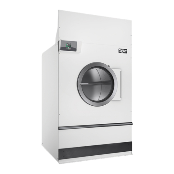
Tumble Dryers
54 Kilogram (120 Pound) Capacity
77 Kilogram (170 Pound) Capacity
91 Kilogram (200 Pound) Capacity
Original Instructions
Keep These Instructions for Future Reference.
(If this machine changes ownership, this manual must accompany machine.)
Starting Serial No. 0907003062
Refer to Page 6 for Model Identification
www.alliancelaundry.com
TMB1268C
TMB1268C
Part No. 70458101ENR3
March 2013
Advertisement
Table of Contents


Need help?
Do you have a question about the 120 Series and is the answer not in the manual?
Questions and answers