Page 1
Tumble Dryers 30 Pound (13 Kilogram) Capacity 35 Pound (16 Kilogram) Capacity 
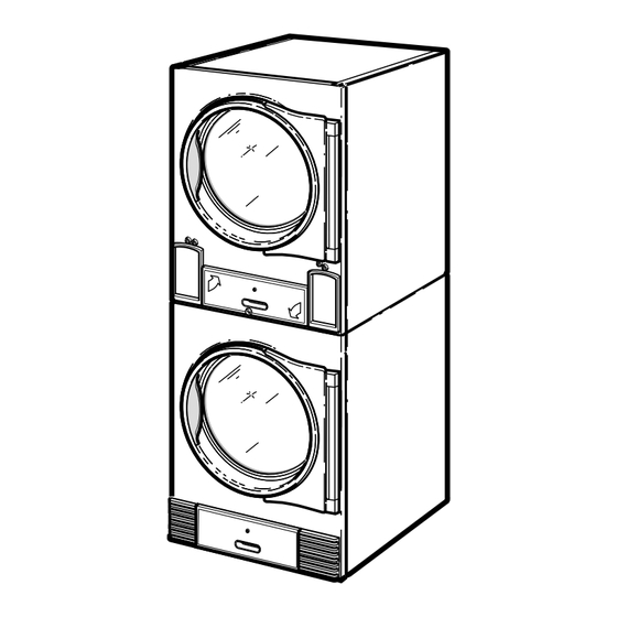
Stacked 30 Pound (13/13 Kilogram) Capacity Stacked 45 Pound (20/20 Kilogram) Capacity 55 Pound (24 Kilogram) Capacity 18 Digit Model Numbers with 6 in 13th Position Refer to Page 12 for Model Identification TMB1292C_SVG Original Instructions Keep These Instructions for Future Reference.
Page 3
Installation must conform with local codes or, in the absence of WARNING local codes, with: In the U.S.A., installation must conform to the latest edition of the American National Standard Z223.1/ NFPA 54 “National • Do not store or use gasoline or other flammable Fuel Gas Code”...
Page 4
WARNING WARNING To reduce the risk of electric shock, fire, explosion, Electrical shock hazard can cause death or serious serious injury or death: injury. To reduce the risk of electric shock, discon- nect all electric power to appliance and accessories •...
Page 5
Users of this product are cautioned not to make modifications or This device contains license-exempt transmitter(s)/receiver(s) changes that are not approved by Alliance Laundry Systems, that comply with Innovation, Science and Economic Develop- LLC. Doing so may void the compliance of this product with ap- ment Canada’s license-exempt RSS(s) standards.
Page 6
Conformity which is available upon request. thorized to the radio or the antenna of the approved device. Alliance Laundry Systems products comply with the requirement TAIWAN of Article 12 as it can be operated in at least one Member State as...
Page 7
China Restriction of hazardous substances (RoHS) China Restriction of hazardous substances (RoHS) The Table of Hazardous Substances/Elements and their Content As required by China’s Management Methods for Restricted Use of Hazardous Substances in Electrical and Electronic Products Hazardous substances Part Name Lead Mercury Cadmium...
Safety Information Safety Information • Do not tumble fiberglass curtains and draperies unless the la- bel says it can be done. If they are dried, wipe out the cylinder with a damp cloth to remove particles of fiberglass. Important Safety Instructions •...
Safety Information • At the end of each working day, close off all main supplies of DANGER gas, steam and electricity. IMPORTANT: For fire suppression equipped tumble Indicates an imminently hazardous situation that, if dryers, electricity and water should NOT be turned not avoided, will cause severe personal injury or off.
Table of Contents Safety Information................. 8 Important Safety Instructions ................8 Explanation of Safety Messages............... 9 Introduction..................12 Machine Identification...................12 Contact Information..................16 Specifications and Dimensions.............. 17 Specifications and Dimensions...............17 Cabinet Dimensions – 030, 035 and 055 Series..........21 Cabinet Dimensions – T30 and T45 Series............23 Exhaust Outlet Locations –...
Page 11
Gas Requirements.................46 Gas Requirements..................46 How to Change Burner Orifice Size............49 How to Adjust Gas Valve Governor/Regulator..........50 Installing CE Gas Tumble Dryer..............51 Adjusting Manifold Pressure for Natural Gas G20 or G25........ 52 Adjusting Supply Pressure for L.P.G. G30 or G31..........52 Converting From Natural Gas to L.P.G.
Introduction Introduction Machine Identification Information in this manual is applicable to these machines. Refer to the serial plate. 30 Series (30 lb / 13 Kg) BA030E BT030N HA030L HU030E NH030N PK030E SJ030E UG030N BA030L BU030E HA030N HU030F NJ030E PK030L SJ030N UH030E BA030N BU030F...
Introduction Heater Digit (Position 6) M - Medium Electric N - Natural Gas P - Low Electric R - Reduced Gas, Natural Gas (Eco Line) S - Steam Contact Information Serial Number _______________________________ Please include a copy of your bill of sale and any service receipts If service is required, contact the nearest Factory Authorized you have.
Specifications and Dimensions Specifications and Dimensions Specifications and Dimensions Refer to machine serial plate for additional specifications. Specifications 030 Series 035 Series 055 Series Weights and Shipping Information Net Weight (approximate): Gas 335 [150] Gas 365 [165] Gas 440 [200]...
Page 18
Specifications and Dimensions Specifications 030 Series 035 Series 055 Series Air Outlet Diameter: Inch Standard Line Standard Line Standard Line [mm] 6.0 [150] 8.0 [200] 8.0 [200] Eco Line Eco Line Eco Line 6.0 [150] 6.0 [150] 8.0 [200] Maximum Airflow: C.F.M.
Page 19
Specifications and Dimensions Specifications 030 Series 035 Series 055 Series Electric Models Heating Element Rating: Standard Line - 21 Standard Line - 24 Standard Line - 27 Kilowatts Eco Line - 12 Medium - 18 Eco Line - 18 Eco Line - 12...
Page 20
Specifications and Dimensions Specifications T30 Series T45 Series Cylinder Size: 30.0 x 26.0 [762 x 660] 33.0 x 30.0 [838 x 762] Inch [mm] Cylinder Capacity (dry weight): 2 x 30 [2 x 13] 2 x 45 [2 x 20] Pounds [kg] Cylinder Volume: 2 x 10.6 [2 x 300]...
Page 21
Specifications and Dimensions Specifications T30 Series T45 Series Door Hinge Side Right Right Door Maximum Open Angle: Degrees Gas Models Gas Connection 1/2 NPT 1/2 NPT Gas Burner Rating (per pocket): Standard Line Standard Line BTU/hr. [kW, Mj/hr.] 73,000 [21.4, 77.0] 95,000 [27.8, 100.2] Eco Line Eco Line...
Specifications and Dimensions Exhaust Outlet Locations – 030, 035 and 055 Series TMB2724N_SVG Rear Exhaust Dimensions, in. [mm] Models Diameter 030 Series Standard Line Eco Line 3.9 [100] 4.6 [115] 6.0 [150] 6.0 [150] 035 Series Standard Line Eco Line 4.9 [125]...
Specifications and Dimensions Exhaust Outlet Locations – T30 and T45 Series TMB2725N_SVG Rear Exhaust Dimensions, in. [mm] Models Diameter T30 Series Standard Line Eco Line 36.5 [930] 4.3 [110] 62.4 [1,585] Elliptical Fits 8.0 Round Fits 6.0 [200] [150] T45 Series Standard Line Eco Line 40.9 [1,040]...
Specifications and Dimensions Gas Connection Locations – 030, 035 and 055 Series TMB2726N_SVG 1. T and G Markets 1/2 NPT; All Other Markets 1/2 BSPT Gas Connection, in. [mm] Models 030 Series 54.2 [1,375] 1.5 [40] 035 Series 54.2 [1,375] 2.6 [65] 055 Series 55.2 [1,400]...
Specifications and Dimensions Gas Connection Locations – T30 and T45 Series TMB2727N_SVG NOTE: Markets H, J, K, L, R and U have an NPT to BSPT adapter included with machine. 1. A Market 1/2 BSPT; All Other Markets 1/2 NPT Gas Connection, in.
Electrical Connection Locations – 030, 035 and 055 Series TMB2728N_SVG 1. Gas and Steam Models: Electrical Connection 1.375 in. [22 mm] Diameter; Electric Models: Electrical Connection Diameter Electrical Service Dimensions, in. [mm] Models 030 Series 33.2 [845] 18.5 [470] 035 Series 33.2 [845] 19.6 [500]...
Specifications and Dimensions Electrical Connection Locations – T30 and T45 Series TMB2729N_SVG 1. Gas Models: Electrical Connection 0.875 in. [22 mm] Diameter; Electric Models: Electrical Connection 1.375 in. [35 mm] Diameter 2. Electrical Connection 1.375 in. [35 mm] Diameter Models Electric Service Dimensions, in.
Installation Installation Pre-Installation Inspection Materials Required (Obtain Locally) Upon delivery, visually inspect the crate, carton and parts for any Steam Models One steam shut-off valve for steam service visible shipping damage. If the crate, carton, or cover is damaged line to be connected upstream of solenoid or signs of possible damage are evident, have the carrier note the steam valve.
Installation If rear of machine or water supply is located in an area where it WARNING will be exposed to cold/freezing temperatures, provisions must be made to protect these water lines from freezing. To reduce the risk of severe injury, clearance of tum- ble dryer cabinet from combustible construction must conform to the minimum clearances, and/or lo- cal codes and ordinances.
Installation Fire Suppression System (Optional Equipment) WARNING ELECTRICAL SHOCK HAZARD. Electrical shock can result in death or serious injury. If the water dispens- ing system is activated, do not attempt to operate T483I_SVG the tumble dryer. If the water dispensing system is activated, have the tumble dryer inspected by a Figure 3 qualified agency before operating the tumble dryer.
Installation IMPORTANT: Temperature of the water supply must be kept between 40°F and 120°F [4.5°C and 49°C] . If water in the supply line or water solenoid valve freezes, the fire suppression system will not operate. IMPORTANT: If temperature sensors inside the tumble dryer register a temperature below 40F°...
Installation Electrical Requirements WARNING Electrical power must be provided to tumble dryer at all times. The fire suppression system will be inoper- ative if the main electrical power supply is discon- nected. W690R1 No independent external power source or supply connection is necessary.
Installation TMB2452N_SVG1 1. Auxiliary Alarm Fast-On Connection (there is a plastic shield over the control board that must be tipped down to access this connection) 2. Test Button 3. Light 4. Reset Button Figure 7 TMB2607N_SVG To Reverse the Loading Door (030, 035 1.
Page 37
Installation TMB2101N_SVG 1. Plug 2. Switch 3. Door Hinge Lug 4. Door Assembly 5. Side Screw Figure 9 TMB2608N_SVG 7. Cut wire ties to remove door switch harness bundle. Be care- 1. Beginning Location of Door Switch ful not to damage harness wires. Refer to Figure 10 . 2.
Installation IMPORTANT: Restore power to tumble dryer and seconds after the door is opened a maximum of 0.79 inches test for proper operation of loading door switch. Re- [20 mm] . If it does not, adjust the loading door switch. Refer fer to Loading Door Switch section for adjustment pro- to Adjustments section.
Installation Prepurge Time Trial for Ignition Reset Lockout Interpurge Time Models (seconds) (seconds) Condition By: (seconds) North America Automatically resets. (attempts to ignite 3 times) Australia and IEC Press start key with ac- cess panel open. If the tumble dryer does not meet ANY of the listed requirements, remove tumble dryer from use. Refer to Removing Tumble Dryer from Service section.
Required Make-Up Air Opening (to the outside) for Each Tumble Dryer, in. W933 WARNING Model Opening Standard 030 Series 110 [710] To reduce the risk of fire, DO NOT use plastic or thin foil ducting to exhaust the tumble dryer. Standard 035/055 Series 144 [930]...
Page 41
Exhaust Requirements NOTE: Proper venting will ensure that any condensate For maximum efficiency and minimum lint accumulation, tumble dryer air must be exhausted to the outdoors by the shortest possi- is subsequently re-evaporated and discharged. ble route. NOTE: On IEC approved tumble dryers where it may Proper sized exhaust ducts are essential for proper operation.
Exhaust Requirements TMB2361N_SVG TMB2362N_SVG TMB2426N_SVG 1. Removable strip of panel in framing wall to permit removal of tumble dryer from framing wall 2. Partition or bulkhead 3. Minimum distance between exhaust opening and roof, ground or other obstruction, 36 in. [910 mm] 4.
Exhaust Requirements mum diameters, and should be increased if the collector length Equivalent Length of exceeds 14 feet [4.3 m] and two 90° elbows. The diameter of a Duct Diameter Rigid Straight Duct round duct must be increased by 10% for each additional 20 feet [6.1 m] .
Page 44
Exhaust Requirements One Manifold Assembly TMB2403N_SVG 1. Outlet duct diameter = largest duct diameter based on number of tumble dryers 2. 45° typical Figure 15 Eco T30 and all 030 035, 055 and Standard Duct Station Series T30 Series T45 Series 6 in.
Page 45
Exhaust Requirements NOTE: Table 13 represents tumble dryers with the same NOTE: Duct clean-out recommended every 6 feet [0.18 vent size. If multiple vent sizes are used, consult a lo- m] . cal HVAC specialist. Two Manifold Assemblies TMB2018N_SVG 1. Outlet duct diameter = combined largest duct diameter of both sides 2.
Gas Requirements Gas Requirements IMPORTANT: The installation must comply with local Gas Requirements codes or, in the absence of local codes: • with the latest edition of the “National Fuel Gas CAUTION Code,” ANSI Z223.1/NFPA 54 in the U.S.A. • with CAN/CSA-B149.1 Natural Gas and Propane In- stallation Code in Canada •...
Page 47
Gas Requirements Maximum 10.5 in. w.c. 2.61 kPa Refer to Table Recommend- 6.5 in. w.c 1.62 kPa Minimum 5 in. w.c. 1.13 kPa An in-line pressure regulator may be required if the line pressure exceeds 10.5 water column inches [26.1 mbar, 2.61 kPa] with all gas appliances running.
Page 48
Gas Requirements Supply Pressure (mbar) Country Category BG, CY, CZ, 2H3B/P DK, EE, FI, G30/31 3B/P (30) 30 (28-30) HR, LT, NO, SE, SI SK 2H3B/P G30/31 3B/P 42.5 57.5 27.5 AT, CH 2H3B/P G30/31 3B/P 42.5 57.5 27.5 CH, ES, GB, 2H3+ GR, IE, IT, TR 3+ (28-30/37)
Gas Requirements 1. Disconnect electrical power from tumble dryer. Close gas shut-off valve to tumble dryer. Refer to Figure 18 . WARNING When converting the tumble dryer to a different gas or pressure, first verify that the supply inlet pressure is equipped with a pressure regulator (located ahead of the tumble dryer) that will main- tain the gas supply at the inlet pressure specified.
• AT/BG/CH/CY/CZ/DK/EE/FI/HR/LT/NO/SE/SI/SK: North America Australia CE Mod- 2H3B/P • CH/ES/GB/GR/IE/IT/TR: II Models Models 2H3+ • DE/LU/PL: II 2E3B/P 030 Series 70550202 70550214 70551902 • Natural Gas, Eco rate • AT/BG/CH/CY/CZ/DK/EE/ES/FI/GB/GR/HR/IE/IT/LT/N T30 Series 70550205 70550211 70551905 O/SE/SI/SK/TR: I • DE/LU/PL: I...
Gas Requirements Low Pressure Gas Pipe Sizes NOTE: Sizing calculations based on National Fuel Gas Code. Gas Pipe Size Required for 1000 BTU Natural Gas (Standard Conditions) at Upstream Pressure— 7.0 ± 1.5 inches water column pressure [17.4 ± 4.0 mbar, 1.74 ± 0.37 kPa] Equivalent Length 25 feet [7.6 50 feet...
Page 55
Gas Requirements Gas Pipe Size Required for 1000 BTU Natural Gas (Standard Conditions) at Upstream Pressure— 7.0 ± 1.5 inches water column pressure [17.4 ± 4.0 mbar, 1.74 ± 0.37 kPa] Equivalent Length 25 feet [7.6 50 feet 75 feet 100 feet [30 125 feet [38 150 feet [46...
Gas Requirements High Pressure Gas Pipe Sizes NOTE: Sizing calculations based on National Fuel Gas IMPORTANT: A high pressure regulator is required at Code. each machine. Gas Pipe Size Required for 1000 BTU Natural Gas (Standard Conditions) at Upstream Pressure — 2.0 ± 0.4 PSI [138 ±...
Gas Requirements High Altitude Burner Orifice Sizing For proper operation at altitudes above 2,000 feet [610 m] , the For IEC models, consult local gas supplier. gas burner orifice size must be reduced to ensure complete com- bustion. Heat input derate of 4% per 1,000 feet [305 meters] of altitude above sea level.
Page 59
Gas Requirements Standard Line Models Altitude Burner Orifice inches Quan- Model Market feet [meters] [mm] tity Part No. 030 Series T, G, A, H, Natural Gas 2,001-4,000 0.1540 70684139 J, K, R, U [610-1,220] [3.91] 4,001-6,000 0.1495 70684137 [1,221-1,830] [3.80] 6,001-8,000 0.1440...
Page 60
Gas Requirements Altitude Burner Orifice inches Quan- Model Market feet [meters] [mm] tity Part No. T30 Series T, G, A, H, Natural Gas 2,001-4,000 0.1540 70684139 J, K, R, U [610-1,220] [3.91] 4,001-6,000 0.1495 70684137 [1,221-1,830] [3.80] 6,001-8,000 0.1440 70684135 [1,831-2,440] [3.66] 8,001-10,000...
Page 61
Gas Requirements Altitude Burner Orifice inches Quan- Model Market feet [meters] [mm] tity Part No. 035 Series T, G, A, H, Natural Gas 2,001-4,000 11/64 0.1719 70684145 J, K, R, U [610-1,220] [4.37] 4,001-6,000 0.1660 70684143 [1,221-1,830] [4.22] 6,001-8,000 0.1610 70684142 [1,831-2,440] [4.09]...
Page 62
Gas Requirements Altitude Burner Orifice inches Quan- Model Market feet [meters] [mm] tity Part No. T45 Series T, G, A, H, Natural Gas 2,001-4,000 0.1730 70684146 J, K, R, U [610-1,220] [4.39] 4,001-6,000 0.1695 70684144 [1,221-1,830] [4.31] 6,001-8,000 0.1610 70684142 [1,831-2,440] [4.09] 8,001-10,000...
Page 63
Gas Requirements Altitude Burner Orifice inches Quan- Model Market feet [meters] [mm] tity Part No. 055 Series T, G, A, H, Natural Gas 2,001-4,000 0.1850 70684150 J, K, R, U [610-1,220] [4.70] 4,001-6,000 0.1800 70684148 [1,221-1,830] [4.57] 6,001-8,000 0.1730 70684146 [1,831-2,440] [4.39] 8,001-10,000...
Page 64
Gas Requirements Eco Line Models (only available in Natural Gas) Altitude Burner Orifice inches Model feet [meters] [mm] Quantity Part No. 030 Series Natural Gas 2,001-4,000 [610-1,220] 3.40 mm 0.1339 [3.40] 70684131 4,001-6,000 [1,221-1,830] 3.30 mm 0.1299 [3.30] 70684130 6,001-8,000 [1,831-2,440] 0.1250 [3.18]...
Electrical Requirements Electrical Requirements IMPORTANT: Electrical connections must be made by a Electrical Requirements qualified electrician using data on serial plate, installa- tion manuals and wiring diagram provided with tumble WARNING dryer and according to local codes. Install a circuit breaker as close to the tumble dryer as possible.
Electrical Requirements The wire colors will be the same regardless of control type. the circuit conductors and connected to the appropriate ground Splice the after-market central pay system wires to the tumble location. dryer control wire harness as follows. • Metal conduit and/or BX cable is not considered ground.
Electrical Requirements Model Heat Source Ground and Terminal Block Locations Electric, low voltage Electric, high voltage TMB2736N_SVG 1. Ground 2. Power Distribution Block Gas/Steam/Electric, low voltage T45 (gas only) Gas/Steam/Electric, high voltage L1 L2 L3 TMB2738N_SVG NOTE: Connection only required in upper junction box.
Electrical Requirements NOTE: Connect this appliance to an individual branch 3. Pull conductors through conduit and attach to circuit breaker and ground connection. Secure service ground wire to the ma- circuit. chine grounding screw or lug. Attach service conductors to NOTE: 3 Phase Only –...
Page 69
Electrical Requirements 100-120 50-60 L1, Neutral, 14 [2.5] and ground 200-240 50-60 Refer to Fig- 14 [2.5] ure 22 440-480 50-60 L1, L2, L3 14 [2.5] and ground 380-415 50-60 L1, L2, L3 14 [2.5] and ground Table 19 055 Series Gas and Steam Models Voltage Code Voltage Cycle...
Page 70
50-60 L1, L2, L3 14 [2.5] and ground 380-415 50-60 L1, L2, L3 14 [2.5] and ground Table 22 21 kW Standard Line 030 Series Electric Models Voltage Code Voltage Cycle Phase Wire Full Load Recommend- Wire Size Amps ed Circuit...
Page 71
Electrical Requirements 460-480 50-60 L1, L2, L3 8 [10] and ground Table 23 12 kW Eco Line 030 Series Electric Models Voltage Code Voltage Cycle Phase Wire Full Load Recommend- Wire Size Amps ed Circuit AWG [mm Breaker Rat- ing Amps...
Page 72
Electrical Requirements 50-60 L1, L2, L3 8 [10] and ground 400-415 50-60 L1, L2, L3 8 [10] and ground 50-60 L1, L2, L3 8 [10] and ground 460-480 50-60 L1, L2, L3 8 [10] and ground Table 25 12 kW Eco Line T30 Series Electric Models (Per Pocket) Voltage Code Voltage Cycle...
Page 73
Electrical Requirements 230-240 50-60 Refer to Fig- 1/0 [50] ure 22 200-208 50-60 L1, L2, L3 3 [26.7] and ground 230-240 50-60 L1, L2, L3 4 [25] and ground 50-60 L1, L2, L3 8 [10] and ground 400-415 50-60 L1, L2, L3 8 [10] and ground 50-60...
Page 74
Electrical Requirements 18 kW Medium 035 Series Electric Models Voltage Code Voltage Cycle Phase Wire Full Load Recommend- Wire Size Amps ed Circuit AWG [mm Breaker Rat- ing Amps 200-208 50-60 Refer to Fig- 1 [35] ure 22 230-240 50-60 Refer to Fig- 3 [26.7] ure 22...
Page 75
Electrical Requirements 27 kW Standard Line 055 Series Electric Models Voltage Code Voltage Cycle Phase Wire Full Load Recommend- Wire Size Amps ed Circuit AWG [mm Breaker Rat- ing Amps 200-208 50-60 Refer to Fig- 2/0 [70] ure 22 230-240 50-60 Refer to Fig- 1/0 [50]...
Steam Requirements Steam Requirements Steam Requirements drain condensate from the low point in the steam header to the return. • In both steam supply and steam return line, it is recommended WARNING that each have a pipe union and shut-off valve. This will ena- ble you to disconnect the steam connections and service the tumble dryer while your laundry facility is in operation.
Page 78
Steam Requirements TMB2646N_SVG NOTE: Refer to Table 33 for sizing of steam lines. Piping must also be sized accordingly for length of runs and number of elbows. 1. Steam Coil 2. 12 in. [300 mm] Riser 3. Condensate Return Line from Supply Line 4.
Adjustments Adjustments Adjustments WARNING To reduce the risk of electric shock, fire, explosion, serious injury or death: • Disconnect electric power to the tumble dryer be- fore servicing. • Close gas shut-off valve to gas tumble dryer be- fore servicing. •...
Adjustments Airflow Switch The airflow switch is set at the factory for proper operation. No adjustment necessary. The airflow switch operation may be affected by shipping wire tie still in place, lack of make-up air, or an obstruction in the ex- haust duct.
Adjustments Manual Resettable Thermostat NOTE: The manual resettable thermostat is located as follows: 030-035-055 - inside access panel on rear of machine near blower motor. T30-T45 - on blower hous- ing top surface behind rear guard. If thermostat trips, contact a qualified service technician. TMB2105N_SVG1 1.
Before You Call for Service Before You Call for Service Won’t Start Won’t Heat Clothes Not Dry Possible Reason – Corrective Actions • Insert correct coin(s) or valid card if applicable. • Close the loading door tightly. • Close lint panel tightly. •...
Removing Tumble Dryer from Service Removing Tumble Dryer from Service 1. Turn off electrical supply external to machine. 2. Turn off gas supply external to machine. 3. Turn off manual gas shut-off valve on machine. 4. Turn off steam supply external to machine. 5.
Disposal of Unit Disposal of Unit This appliance is marked according to the European directive 2002/96/EC on Waste Electrical and Electronic Equipment (WEEE). This symbol on the product or on its packaging indicates that this product shall not be treated as household waste. Refer to Figure 28 .
Need help?
Do you have a question about the 030 Series and is the answer not in the manual?
Questions and answers