Table of Contents
Advertisement
Quick Links
®
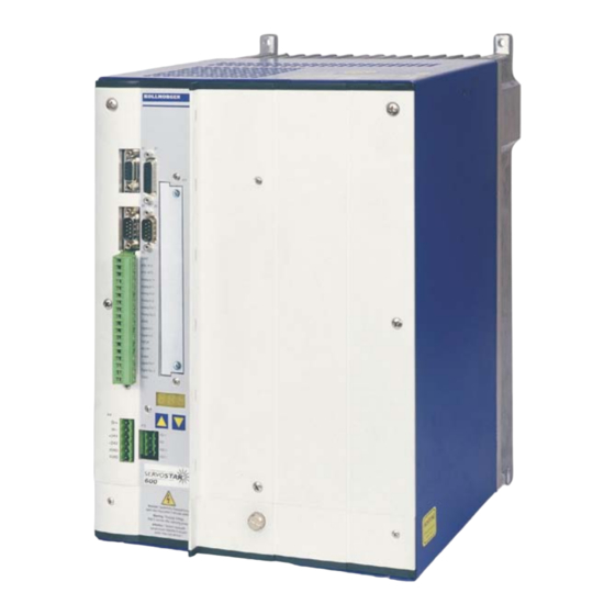
SERVOSTAR
640 / 670
Digital Servo Amplifier
Instructions Manual
Edition 12/2010
Translation of the original manual.
Valid for Hardware Revision 02.10
Keep all manuals as a product component
during the life span of the product.
Pass all manuals to future users / owners
of the product.
File sr640_e.***
Advertisement
Table of Contents


Need help?
Do you have a question about the SERVOSTAR 640 and is the answer not in the manual?
Questions and answers
Servo amplifier Kollmorgen ServoStar 640 art. no. S64001-NA
The Kollmorgen SERVOSTAR 640 servo amplifier with part number S64001-NA is a model without a built-in expansion card. It is part of the SERVOSTAR 640/670 series. When ordered, the package includes:
- The SERVOSTAR 640 amplifier
- Mating connectors for X3 and X4
- Assembly and installation instructions (manual)
- Online documentation on CD-ROM
- Setup software (DRIVE.EXE) on CD-ROM
Accessories must be ordered separately and may include:
- Mains filter (3EF) and mains choke (3L)
- AC servomotor (linear or rotary)
- Motor, brake, and feedback cables
- External brake resistor (BAS)
- Communication cable or Y-adapter for PC connection
- Power, control, and fieldbus cables
The amplifier must be used with proper external components for full functionality.
This answer is automatically generated