
Related Manuals for Kollmorgen ServoStar 400


Summary of Contents for Kollmorgen ServoStar 400
- Page 1 www.DanaherMotion.com Digital Servo Amplifier ® SERVOSTAR Assembly, Installation, Setup Edition 07/05 File sr400_d.xxx Order No.: 102530...
- Page 2 HIPERFACE is a registered trademark of Max Stegmann GmbH EnDat is a registered trademark of Dr.Johannes Heidenhain GmbH SERVOSTAR is a registered trademark of Kollmorgen Corporation Technical changes to improve the performance of the equipment may be made without notice ! Printed in the Federal Republic of Germany All rights reserved.
-
Page 3: Table Of Contents
Digital servo amplifiers in the series SERVOSTAR 400........ - Page 4 Connection to SERVOSTAR 400 master, 5V level (X4) ....... . .
-
Page 5: General
Kollmorgen General 07/05 General About this manual This manual describes the digital servo amplifiers of the SERVOSTAR 400 series. In this manual you can find information about: General Chapter 1 Technical description Chapter 2 Assembly / installation Chapter 3 Interfaces... -
Page 6: Abbreviations Used In This Manual
General Kollmorgen 07/05 Abbreviations used in this Manual The abbreviations used in this manual are explained in the table below. Abbrev. Meaning AGND Analog ground BTB/RTO Ready to operate Fieldbus (CANopen) Communité Europeenne (=EC) Clock signal Serial interface for a PC-AT... -
Page 7: Technical Description
Kollmorgen Technical description 07/05 Technical description Safety Instructions Only properly qualified personnel are permitted to carry out activities such as transport, installation, commissioning and maintenance. Properly qualified persons are those who are familiar with the transport, assembly, installation, commissioning and operation of the product, and who have the appropriate qualifications for their job. -
Page 8: Use As Directed
If the servo amplifiers are used in residential areas, or in business or commercial premi- ses, then additional filter measures must be implemented by the user. The SERVOSTAR 400 family of servo amplifiers is only intended to drive specific brushless synchronous servomotors with closed-loop control of torque, speed and/or position. -
Page 9: European Directives And Standards
Kollmorgen Technical description 07/05 European Directives and Standards Servo amplifiers are components that are intended to be incorporated into electrical plant and machines for industrial use. When the servoamplifiers are built into machines or plant, the intended operation of the amplifier is forbidden until it has been established that the machine or plant fulfills the requirements of the EC Machinery Directive 98/37/EG and the EC Directive on EMC (89/336/EEC) and the Low Voltage Directive 73/23/EEC. -
Page 10: Ul And Cul- Conformance
Technical description Kollmorgen 07/05 UL and cUL- Conformance UL (cUL)-certified servo amplifiers (Underwriters Laboratories Inc.) fulfil the relevant U.S. and Canadian standard (in this case UL 840 and UL 508C). This standard describes the fulfilment by design of minimum requirements for electrically... -
Page 11: Nameplate
Barcode Firmware Serial Number Equipment description 2.7.1 Package as supplied If you order a SERVOSTAR 400 series amplifier from us, you will receive: — SERVOSTAR 4xxM (master) — Mating connectors for X0, X1, X3, X6 — Protective cover for the axis-side (required only once per system) —... -
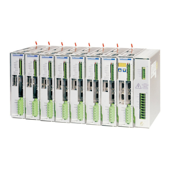
Page 12: Digital Servo Amplifiers In The Series Servostar 400
Technical description Kollmorgen 07/05 2.7.2 Digital servo amplifiers in the series SERVOSTAR 400 Minimum complexity up to 8 axes in a single system only one power supply feed and one auxiliary voltage supply per system shield connection directly on the servo amplifier... - Page 13 Kollmorgen Technical description 07/05 Integrated safety safe electrical separation to EN 50178 between the power input / motor connections and the signal electronics, provided by appropriate creepage distances and complete electrical isolation Soft-start, overvoltage detection, short-circuit protection, phase-failure monitoring temperature monitoring of servo amplifier and motor (when using our motors with our...
-
Page 14: Components Of A Servo System
Technical description Kollmorgen 07/05 Components of a servo system Control / PLC 24V supply SERVOSTAR 400 fuses drive contactor terminals motor ® SERVOSTAR 400 Installation Manual... -
Page 15: Technical Data
Kollmorgen Technical description 07/05 Technical data 2.9.1 Rated data max. 230VAC max. 400VAC SERVOSTAR SERVOSTAR Rated data DIM 403M 406M 403A 406A 443M 446M 403A 406A 1 x 115V 3 x 230V -10% -10% Rated supply voltage — — 3 x 230V... -
Page 16: Connections
Technical description Kollmorgen 07/05 2.9.2 Connections Function Connector type Control signals Combicon spring terminal Power supply Power Combicon Motor Combicon Resolver input SubD 9pol. (socket) Incremental encoder input SubD 15pol. (socket) PC interface SubD 9pol. (plug) Encoder simulation, ROD/SSI SubD 9pol. (plug) 2.9.3... -
Page 17: Permissible Ambient Conditions, Ventilation, Mounting Position
Kollmorgen Technical description 07/05 2.9.5 Permissible ambient conditions, ventilation, mounting position ð p.67 Storage temp. /humidity/duration ð p.67 Transport temperature/humidity Supply voltage tolerances main power +10% SERVOSTAR 40xM min 1x115V AC / max 1x230V , 50/60 Hz -10% +10% min 3x115V... -
Page 18: Motor Holding Brake Control
Technical description Kollmorgen 07/05 2.10 Motor holding brake control A motor holding brake (24V / max.1.5A) can be controlled directly by the servo amplifier. This function does not ensure personnel safety! The brake function must be enabled through the BRAKE parameter (on the screen page for Motor): the setting is WITH. -
Page 19: Regen Circuit
Kollmorgen Technical description 07/05 2.11 Regen circuit During braking with the aid of the motor, energy is fed back to the servo amplifier. This energy is converted into heat in the regen resistor. The regen resistor is switched in and out by the regen circuit. -
Page 20: Switch-On/-Off Behaviour
Technical description Kollmorgen 07/05 2.13 Switch-on/-off behaviour The diagram below illustrates the correct functional sequence for switching the servo amplifier on and off. 2.13.1 Stop function as per EN 60204 (VDE 0113) If a fault occurs (ð p.60), the output stage of the servo amplifier is switched off and the BTB/RTO contact is opened. -
Page 21: Emergency Stop Methods
In multi-axis systems (several SERVOSTAR 400-systems or combinations of SERVOSTAR 400 and SERVOSTAR 300 or 600) using a coupled DC Bus link the motor cable must also be disconnected by a changeover switch (a contactor, such as Siemens type 3RT1516-1BB40) and short-circuited by resistors wired in a star configuration. - Page 22 Technical description Kollmorgen 07/05 This page has been deliberately left blank. ® SERVOSTAR 400 Installation Manual...
-
Page 23: Installation
Kollmorgen Installation 07/05 Installation Important notes Protect the servo amplifier from impermissible stresses. In particular, do not let any components become bent or any insulation distances altered during transport and handling. Avoid contact with electronic components and contacts. Check the combination of servo amplifier and motor. Compare the rated voltage and current of the units. -
Page 24: Guide To Installation/Wiring
Installation Kollmorgen 07/05 Guide to installation/wiring The following notes should assist you to carry out the installation in a sensible sequence, without overlooking anything important: In a closed control cabinet. Observe page 17. Site The site must be free from conductive or corrosive materials. -
Page 25: Mounting
2 mounting rails to EN60715, min. length = system width + 40mm, make sure there is a conductive connection to the mounting plate Mount the protective cover (7mm) on the left side of the system. Tools required: Screwdriver with approx. 5 mm blade width SERVOSTAR 400 ® SERVOSTAR 400 Installation Manual... -
Page 26: Dimensions
Installation Kollmorgen 07/05 3.3.1 Dimensions SERVOSTAR 400M SERVOSTAR 400A ® SERVOSTAR 400 Installation Manual... -
Page 27: Wiring
Kollmorgen Installation 07/05 Wiring Only professional staff who are qualified in electrical engineering are allowed to install the servo amplifier. The installation procedure is described as an example. A different procedure may be appropriate or necessary, depending on the application of the equipment. -
Page 28: Wiring Diagram Master
Installation Kollmorgen 07/05 3.4.1 Wiring diagram master Follow the safety instructions (ð p.7) and the use as directed (ð p.8) ! SERVOSTAR 400M ð p.40 ð p.41 ð p.42 ð p.39 ð p.43 ð p.38 ð p.44 ð p.47 ð p.38 ð... -
Page 29: Wiring Diagram Axis Module
Kollmorgen Installation 07/05 3.4.2 Wiring diagram axis module Follow the safety instructions (ð p.7) SERVOSTAR 400A and the use as directed (ð p.8) ! ð p.40 ð p.41 ð p.42 ð p.39 ð p.43 ð p.38 ð p.47 ð p.52 ®... -
Page 30: Example Of Connections For Multi-Axis System
Installation Kollmorgen 07/05 3.4.3 Example of connections for multi-axis system Follow the safety instructions (ð p.7) and the use as directed (ð p.8) ! SERVOSTAR 400M SERVOSTAR 400A SERVOSTAR 400A ® SERVOSTAR 400 Installation Manual... -
Page 31: Connector Assignments
Kollmorgen Installation 07/05 3.4.4 Connector assignments ® SERVOSTAR 400 Installation Manual... -
Page 32: Connection Techniques
Connection techniques 3.4.5.1 Shield connection on the front panel The pre-assembled cables for SERVOSTAR 400 are provided with an overall metal ferrule at the amplifier end that is electrically connected to the shielding. Thread a cable tie through each slot in the shielding strip (front panel) of the servo amplifier. -
Page 33: Requirements To Cables
Kollmorgen Installation 07/05 3.4.5.2 Requirements to cables Further information on the chemical, mechanical and electrical characteristics of the cables can be obtained from our customer support. Insulation material Sheathing PUR (polyurethane, code 11Y) Core insulation PETP (polyesteraphthalate, code 12Y) Capacitance... -
Page 34: Setup Software
The operator software is intended to be used for altering and storing the operating para- meters for the SERVOSTAR 400 series of servo amplifiers. The attached servo amplifier is commissioned with the assistance of the software - during this process the drive can be controlled directly by the service functions. -
Page 35: Hardware Requirements
PC. Connection to the serial interface of the PC Connect the interface cable to a serial interface on your PC and the PC interfaces (X8) of the SERVOSTAR 400 (ð p.51). Installation Insert the CD-ROM into a free drive. -
Page 36: Interfaces
Interfaces Kollmorgen 07/05 Interfaces This chapter presents all the important interfaces, divided between master and axis module. The precise location of the connectors and terminals can be seen on page 31. Block diagram ® SERVOSTAR 400 Installation Manual... -
Page 37: Power Supply, Master Only
Mains supply connection (X0) 4.2.1.1 Three-phase supplies Directly to earthed supply, filter is integrated, fusing (e.g. fusible cut-outs) to be provided by the user (ð p.16). SERVOSTAR 400 for SERVOSTAR40xM for SERVOSTAR44xM 4.2.1.2 Single-phase supplies Directly to supply, filter is integrated, fusing (e.g. fusible cut-outs) to be provided by the user (ð... -
Page 38: Auxiliary Voltage (X0)
— Required current rating (ð p.15) — Integrated EMC filter for the 24V auxiliary supply SERVOSTAR 400 DC Bus link/DC-bus (X0) Can be connected in parallel with further, identical masters (via terminals -DC and RB Motor connection with brake (X6) Max. -
Page 39: External Regen Resistor (X0), Master Only
Resolver connection (X5) Our rotary servomotors have 2-pole hollow-shaft resolvers built in as a standard. It is possible to connect 2- to 32-pole resolvers to SERVOSTAR 400. If lead lengths of more than 25m are planned, please consult our customer support. -
Page 40: Encoder Connection (X2)
Preferred types are the ECN1313 and EQN1325 encoders. The encoder is used by the SERVOSTAR 400 as a feedback device for drive tasks that require highly precise positio- ning or extremely smooth running. If lead lengths of more than 25m are planned, please consult our customer support. -
Page 41: Control Signals
— Input resistance 20 kW — Common mode voltage range for both inputs ± 10 V supplementary SERVOSTAR 400 Analog input (terminals X3/2-3) Input voltage max. ± 10 V, 14-bit resolution, scalable Standard setting: Speed Setpoint Fixing the direction of rotation... -
Page 42: Digital Control Inputs (X3)
The logic is dimensioned for +24V / 7mA (PLC-compatible) — H-level from +12...36V / 7mA, L-level from 0...7V / 0 mA SERVOSTAR 400 You can use the digital inputs PSTOP / NSTOP / DIGITAL-IN1 and DIGITAL-IN2 to initiate pre-programmed functions that are stored in the servo amplifier. -
Page 43: Digital Control Outputs (X3)
Alle digital outputs are floating — DIGITAL-OUT1 and 2 : Open-collector, max. 30V DC, 10mA SERVOSTAR 400 Programmable digital outputs DIGITAL-OUT 1 / 2: You can use the digital outputs DIGITAL-OUT1 (terminal X3/8) and DIGITAL-OUT2 (terminal X3/9) to output messages from pre-programmed functions that are stored in the servo amplifier. -
Page 44: Digital Control Signals On The Master (X1)
— H-level from +12...36V / 7mA, L-level from 0...7V / 0 mA BTB/RTO: Relay output, max. 30V DC or 42V AC, 0.5A SERVOSTAR 400 ENABLE input The output stage of the servo amplifier is activated by the enable signal (terminal X1/3, input 24V, active-high). -
Page 45: Encoder Simulations
The ground reference for the interface is PGND. PGND must always be connected to the control ground. The max. admissible cable length is 10 m. Connections and signal description for the incremental-encoder interface : SERVOSTAR 400 ® SERVOSTAR 400 Installation Manual... -
Page 46: Ssi Output (X4)
Connection and signals for the SSI interface : The count direction for the SSI interface is UP when the motor shaft is rotating clockwise (looking at the end of the motor shaft). SERVOSTAR 400 ® SERVOSTAR 400 Installation Manual... -
Page 47: Input Encoder Control For Master-Slave Operation
07/05 4.8.3 Input encoder control for master-slave operation This interface can be used to link several SERVOSTAR 400 amplifiers in master-slave operation. The parameters for the slave amplifier are set up with the aid of the setup software (elec- trical gearing). The resolution (no. of pulses/turn) can be adjusted. The analog setpoint input is inactive. -
Page 48: Connection To Encoder With 24V Signal Level (X3)
4.8.3.2 Connection to encoder with 24V signal level (X3) You can use this interface to set up the SERVOSTAR 400 as a slave following an enco- der with a 24V signal level (master-slave operation). This application uses the digital inputs DIGITAL-IN 1 and 2 on connector X3. -
Page 49: Interface For Stepper Motor Controls (Pulse/Direction)
Kollmorgen Interfaces 07/05 Interface for stepper motor controls (pulse/direction) This interface can be used to connect the servo amplifier to a third-party stepper-motor controller. The parameters for the servo amplifier are set up with the aid of the setup soft- ware (electrical gearing). -
Page 50: Connection Of Stepper Motor Controls With 5V Signal Level (X4)
5V signal level. The SubD connector X4 is used for this purpose. Limit frequency: 1 MHz AGND (terminal X3/1) must be connected to the ground of the control system! SERVOSTAR 400 4.9.2 Connection of stepper motor controls with 24V signal level (X3) You can use this interface to connect the servo amplifier to a stepper motor control with a 24V signal level. -
Page 51: Rs232 Interface, Pc Connection (X8), Master Only
Further notes can be found on page 34 . SERVOSTAR 400 Interface cable between the PC and servo amplifiers of the SERVOSTAR 400 series: (View: front view of the built-in SubD connectors, this corresponds to looking at the solder side of the SubD connector on the cable.) ®... -
Page 52: Fieldbus Connection
The interface is at the same potential as the internal logic, and uses AGND as the ground reference. AGND must be connected to the control system ground for potential equalization! SERVOSTAR 400 CAN bus cable To meet ISO 11898 you should use a bus cable with a 120 W characteristic impedance. -
Page 53: Profibus Interface (X7), Option
07/05 4.11.2 PROFIBUS interface (X7), option This section describes the PROFIBUS interface for SERVOSTAR 400. Information on the range of functions and the software protocol can be found in the manual “Communication profile PROFIBUS-DP”. The selection of cables, cable routing, shielding, bus connectors, bus termination and propagation times are described in the “Setup guidelines for PROFIBUS-DP/FMS”... -
Page 54: Sercos Interface (X7), Option
4.11.3 SERCOS interface (X7), option This section describes the SERCOS interface of the SERVOSTAR 400. Information on the range of functions and the software protocol can be found in the manual “IDN Refer- ence Guide SERCOS”. For the optical fibre (LWL) connection, only use SERCOS compo- nents to the SERCOS Standard IEC 61491. -
Page 55: Setup
Kollmorgen Setup 07/05 Setup Important notes Only professional personnel with extensive knowledge in the fields of electrical engineering and drive technology are allowed to setup the servo amplifier. The procedure for commissioning is described as an example. Depending on the applica- tion, a different procedure may be appropriate or necessary. -
Page 56: Guide To Setup
Setup Kollmorgen 07/05 Guide to setup The following instructions should help you to carry out the commissioning in a sensible order, without any hazards to people or machinery: See Chapter 3. Disconnect the servo amplifier from Check installation the supply. -
Page 57: Parameterization
Kollmorgen Setup 07/05 Parameterization A default parameter set is loaded into your servo amplifier at the factory. This contains valid and safe parameters for the current and speed controllers. A database for motor parameters is stored in the servo amplifier. During commissioning you must select the data set for the motor that is connected and store it in the servo amplifier. -
Page 58: Key Pad Controls And Status Displays
Setup Kollmorgen 07/05 5.3.2 Key pad controls and status displays Two keys are fitted in the operating panel of the master. Here you can enter the basic address for the system and call up status information on all the axes that are connected. -
Page 59: Status Display On The Master
Kollmorgen Setup 07/05 5.3.2.3 Status display on the master ® SERVOSTAR 400 Installation Manual... -
Page 60: Error Messages
Setup Kollmorgen 07/05 Error messages Any errors that occur are shown in coded form by an error number in the LED display on the front panel. All error messages result in the BTB/RTO contact being opened, and the output stage of the amplifier being switched off (motor loses all torque). The motor-hol- ding brake is activated. -
Page 61: Warning Messages
Kollmorgen Setup 07/05 Warning messages Faults which occur, but which do not cause a switch-off of the amplifier output stage (BTB/RTO contact remains closed), are indicated in the LED display on the front panel by a coded warning number. Number... - Page 62 Setup Kollmorgen 07/05 This page has been deliberately left blank. ® SERVOSTAR 400 Installation Manual...
-
Page 63: Accessories
Kollmorgen Accessories 07/05 Accessories External PSU 24V DC / 5A Technical data Input voltage 120 / 230V Input current 0.9 / 0.6A Frequency 50/60Hz Primary fusing 3.15AT Output voltage 24V ± 1% Max. output current 5A Residual ripple <150mVss Switching peaks <240mVss... -
Page 64: External Psu 24V Dc / 20A
Accessories Kollmorgen 07/05 External PSU 24V DC / 20A Mounting plate Mounting plate Technical data Input voltage 3 x 400V AC ± 10% Input current approx. 1.1A Frequency 50/60Hz Primary fusing none Output voltage 24V ± 1% Max. output current 20A Residual ripple <0.1%... -
Page 65: External Regen Resistor Bar(U)Xyz
Kollmorgen Accessories 07/05 External regen resistor BAR(U)xyz Caution: Surface temperature may exceed 200°C. Observe the requested free space. Do not mount to combustible surface. ® SERVOSTAR 400 Installation Manual... -
Page 66: Add-On Fan
Accessories Kollmorgen 07/05 Add-on fan Electrical add-on fan for two axes to achieve rated power even under unfavourable ambient conditions, required for SERVOSTAR4x6. To mount the fan, just hook it in the designated slots at the bottom of the SERVOSTAR and screw the fixing bolt into the thread in the housing. -
Page 67: Appendix
Kollmorgen Appendix 07/05 Appendix Transport, storage, maintenace, disposal Transport: — only by qualified personnel — only in the manufacturer’s original recyclable packaging — avoid shocks — temperature -25 to +70°C, max. rate of change 20°C/hour — humidity max. 95% relative humidity, no condensation —... -
Page 68: Fault-Finding
Appendix Kollmorgen 07/05 Fault-finding The table below should be regarded as a “First-aid” box. Depending on the conditions in your installation, there may be a wide variety of reasons for the fault. In multi-axis systems there may be further hidden cau- ses of a fault. - Page 69 Kollmorgen Appendix 07/05 Fault possible causes Measures to remove the fault — wrong cable — check wiring F25 message: — wrong phasing — check resolver poles (RESPOLES) + Commutation er- motor poles (MPOLES) + offset (MPHA- — servo amplifier not enabled —...
-
Page 70: Glossary
Appendix Kollmorgen 07/05 Glossary clock Clock signal common-mode voltage The maximum amplitude of a disturbance (on both inputs) which a differential input can eliminate continuous power of regen circuit Mean power which can be dissipated in the regen circuit counts... - Page 71 Kollmorgen Appendix 07/05 P-controller Control loop with purely proportional behaviour phase shift Compensation for the lag between the electro- magnetic and magnetic fields in the motor PID-controller Control loop with proportional, integral and differential behaviour PID-T2 Filter time constant for the speed controller output...
-
Page 72: Order Numbers
Appendix Kollmorgen 07/05 Order numbers Product Order numbers Europa SERVOSTAR 403M-CANopen 102111 SERVOSTAR 406M-CANopen 102117 SERVOSTAR 443M-CANopen 102832 SERVOSTAR 446M-CANopen 102833 SERVOSTAR 403A-CANopen 102112 SERVOSTAR 406A-CANopen 102118 SERVOSTAR 403M-PROFIFIBUS 102113 SERVOSTAR 406M-PROFIFIBUS 102119 SERVOSTAR 443M-PROFIFIBUS 102834 SERVOSTAR 446M-PROFIFIBUS 102835 SERVOSTAR 403A-PROFIFIBUS... - Page 73 Kollmorgen Appendix 07/05 This page has been deliberately left blank. ® SERVOSTAR 400 Installation Manual...
-
Page 74: Index
Appendix Kollmorgen 07/05 Index 24V aux. supply, interface ..38 hardware requirements ..35 humidity ....67 abbreviations . - Page 75 Kollmorgen Appendix 07/05 package supplied ..11 technical data ... . 15 packaging ....67 ambient conditions .
- Page 76 www.DanaherMotion.com S a l e s a n d S e r v i c e We are committed to quality customer service. In order to serve in the most effective way, please contact your local sales representative for assistance. If you are unaware of your local sales representative, please contact us.
Need help?
Do you have a question about the ServoStar 400 and is the answer not in the manual?
Questions and answers