Table of Contents
Advertisement
Quick Links
Danaher Motion S71201-SE
Digital Servo Amplifier
A l l t r a d e m a r k s , b r a n d n a m e s , a n d b r a n d s a p p e a r i n g h e r e i n a r e t h e p r o p e r t y o f t h e i r r e s p e c t i v e o w n e r s .
• C r i t i c a l a n d e x p e d i t e d s e r v i c e s
• I n s t o c k / R e a d y - t o - s h i p
Artisan Scientific Corporation dba Artisan Technology Group is not an affiliate, representative, or authorized distributor for any manufacturer listed herein.
Limited Availability
Used and in Excellent Condition
Open Web Page
https://www.artisantg.com/66130-2
• We b u y y o u r e x c e s s , u n d e r u t i l i z e d , a n d i d l e e q u i p me n t
• F u l l - s e r v i c e , i n d e p e n d e n t r e p a i r c e n t e r
Advertisement
Table of Contents

Related Manuals for Kollmorgen S71201-SE


Summary of Contents for Kollmorgen S71201-SE
- Page 1 Danaher Motion S71201-SE Digital Servo Amplifier Limited Availability Used and in Excellent Condition Open Web Page https://www.artisantg.com/66130-2 A l l t r a d e m a r k s , b r a n d n a m e s , a n d b r a n d s a p p e a r i n g h e r e i n a r e t h e p r o p e r t y o f t h e i r r e s p e c t i v e o w n e r s .
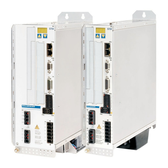
- Page 2 S700 Digital Servo Amplifier S70101...S72401 (STO single channel) Instruction Manual Translation of the original instruction manual. Edition 12/2010a Valid for Hardware Revision 02.10 Keep all manuals as a product component during the life span of the product. Pass all manuals to future users / owners of the product.
- Page 3 Printed in the Federal Republic of Germany All rights reserved. No part of this work may be reproduced in any form (by photocopying, microfilm or any other method) or stored, processed, copied or distributed by electronic means without the written permission of KOLLMORGEN Europe GmbH.
-
Page 4: Table Of Contents
Kollmorgen Contents 12/2010a P a g e General About this manual ..............7 Target group . - Page 5 Contents Kollmorgen 12/2010a P a g e 6.9.8 Functional description ............40 6.9.8.1...
- Page 6 Kollmorgen Contents 12/2010a P a g e 8.14 Digital and analog inputs and outputs ..........81 8.14.1...
- Page 7 Contents Kollmorgen 12/2010a P a g e 10.1.5 Expansion card - DEVICENET - ..........114 10.1.5.1 Front view .
-
Page 8: General
Kollmorgen General 12/2010a General About this manual This manual describes the S70101-S72401 series of digital servo amplifiers (standard version: 1.5A ...24A rated current, single channel STO). A more detailed description of the expansion cards that are currently available and the... -
Page 9: Abbreviations Used
General Kollmorgen 12/2010a Abbreviations used Abbrev. Meaning AGND Analog ground Fuse, x Amps, fast Fuse, x Amps, medium Fuse, x Amps, slow BTB/RTO Ready to operate Fieldbus (CANopen) Communité Europeenne Clock signal Serial interface for a Personal Computer DGND Digital ground (for 24V and digital I/O) -
Page 10: Symbols Used
Kollmorgen General 12/2010a Symbols used Symbol Indication Indicates a hazardous situation which, if not avoided, will result in death or serious injury. Indicates a hazardous situation which, if not avoided, could result in death or serious injury. Indicates a hazardous situation which, if not avoided, could result in minor or moderate injury. -
Page 11: Safety
Safety Kollmorgen 12/2010a Safety Safety Instructions During operation there are deadly hazards, with the possibility of death, severe injury or material damage. Do not open or touch the equipment during operation. Keep all covers and cabinet doors closed during operation. Touching the equipment is allowed during installation and commissioning for properly qualified persons only. -
Page 12: Use As Directed
Kollmorgen Safety 12/2010a Use as directed Servo amplifiers are safety components that are built into electrical plant or machines, and can only be operated as integral components of such plant or machines. The manufacturer of the machine must generate a hazard analysis for the machine, and take appropriate measures to ensure that unforeseen movements cannot cause injury or damage to any person or property. -
Page 13: Prohibited Use
Safety Kollmorgen 12/2010a Prohibited use Other use than described in chapter 2.2 is not intended and can lead to damage of per- sons, equipment or things. The use of the servo amplifier in the following environments is prohibited: potentially explosive areas... -
Page 14: Approvals
Kollmorgen Approvals 12/2010a Approvals Conformance with UL This servo amplifier is listed under UL file number E217428. UL-certified servo amplifiers (Underwriters Laboratories Inc.) fulfil the relevant U.S. stan- dards (in this case UL 840 and UL 508C). This standard describes the fulfillment by design of minimum requirements for electrically... -
Page 15: Ul Certificate Of Compliance
Approvals Kollmorgen 12/2010a 3.1.2 UL Certificate of Compliance Certificate for servo amplifiers S700 (cover page). S701...S724 (single channel STO) Instruction Manual... -
Page 16: Ec Conformance
Kollmorgen Approvals 12/2010a EC conformance Conformance with the EC Machine Directive 2006/42/EC, the EC EMC Directive 2004/108/EC and the Low Voltage Directive 2006/95/EC is mandatory for the supply of servo amplifiers within the European Community. The servo amplifier meets the noise immunity requirements to the 2nd environmental cat- egory (industrial environment). -
Page 17: Ec Declaration Of Conformity
Approvals Kollmorgen 12/2010a 3.2.2 EC Declaration of Conformity S701...S724 (single channel STO) Instruction Manual... -
Page 18: Gost-R Conformance
Kollmorgen Approvals 12/2010a GOST-R conformance Certificate for servo amplifiers and accessories (cover page). S701...S724 (single channel STO) Instruction Manual... - Page 19 Approvals Kollmorgen 12/2010a This page has been deliberately left blank. S701...S724 (single channel STO) Instruction Manual...
-
Page 20: Handling
Kollmorgen Handling 12/2010a Handling Transport Transport by qualified personnel in the manufacturer’s original recyclable packaging Avoid shocks while transporting Transport temperature: -25 to +70°C, max. rate of change 20K / hour, class 2K3 acc. to EN61800-2 Transport humidity: max. 95% relative humidity, no condensation, class 2K3 acc. -
Page 21: Disassembling
Handling Kollmorgen 12/2010a Disassembling Observe the sequence below, if a servo amplifier has to be disassembled (e.g. for replacement). 1. Electrical disconnection Switch off the main switch of the switchgear cabinet and the fuses that supply the system. Wait at least eight minutes after disconnecting the servo amplifier from the main supply power before touching potentially live sections of the equipment (e.g. -
Page 22: Package
Kollmorgen Package 12/2010a Package Package supplied When an amplifier from the S700 series is ordered (order numbers ðp.133), the following is supplied: — Servo amplifier S700 — Instruction Manual S700 — Online documentation and setup software on CD-ROM — Mating connectors X0, X3A, X3B, X4A, X4B, X8 The mating SubD connectors are not part of the package! Accessories : (must be ordered separately, if required;... -
Page 23: Part Number Scheme
Package Kollmorgen 12/2010a Part number scheme The part number is identical with the order code. S 7 0 6 0 1 - EI F2 PM - NA - 000 Family Firmware Options S700 no option (EtherCAT&CANopen) Current Rating 1.5 Arms... -
Page 24: Technical Description
Kollmorgen Technical description 12/2010a Technical description The S700 family of digital servo amplifiers Standard version + 10% Large supply voltage range: 3 x 208V … 3 x 480V -10% Overvoltage category III acc. to IEC 61800-5-1 2 housing dimensions: S701...S712... - Page 25 Technical description Kollmorgen 12/2010a Integrated safety Appropriate insulation/creepage distances and electrical isolation ensure safe electri- cal separation, as per IEC 61800-5-1, between the power input / motor connections and the signal electronics. Soft-start, overvoltage detection, short-circuit protection, phase-failure monitoring. Temperature monitoring of the servo amplifier and motor (if our motors and prefabri- cated cables are used).
- Page 26 Several third-party expansion cards (ModBus, LightBus, FIP-IO etc. please contact the manufacturer for further information) Macro programming More information can be found in our Product-WIKI ( www.wiki-kollmorgen.eu). 62.5µs / 250µs / 1ms / 4ms / 16ms / IDLE / IRQ 128 kByte memory IEC 61131 structured text 400 easy instructions every 62.5 µs...
-
Page 27: Technical Data
Technical description Kollmorgen 12/2010a Technical data 6.2.1 Rated Data S71201/ S72401/ Electrical data S70101 S70301 S70601 S7120P S7240P Rated supply voltage 3 x 208V … 3 x 480V +10% , 50/60 Hz -10% (grounded supply, phase to phase) Rated input power for S1 operation Permitted switch on/off frequency ð... -
Page 28: Inputs / Outputs, Aux. Voltage Supply
Kollmorgen Technical description 12/2010a 6.2.2 Inputs / outputs, aux. voltage supply Interface electr. data ±10V Analog inputs 1/2 ±10V Max. common-mode voltage as per IEC 61131-2 type1, Digital control inputs max. 30VDC, 15mA as per IEC 61131-2 type1, Digital control outputs max. -
Page 29: Ambient Conditions, Ventilation, Mounting Position
To reach functional safety with the max. permitted cable length, observe cable requirements ð p. 53. * Kollmorgen North America supplies cables up to 39 meters Kollmorgen Europe supplies cables up to max. length S701...S724 (single channel STO) Instruction Manual... -
Page 30: Motor Holding Brake
Kollmorgen Technical description 12/2010a Motor holding brake A 24V / max. 2A holding brake in the motor can be controlled directly by the amplifier. This function does not ensure personnel safety! Hanging load (vertical axes) require an additional mechanical brake which must be safely operated. -
Page 31: Led Display
"Product Wiki" which is acces- sible at www.wiki-kollmorgen.eu. A description of the interface can be found on page 60. Functional description: 1.- Individual amplifiers, not coupled through the DC bus link circuit (DC+, DC-) - Page 32 Kollmorgen Technical description 12/2010a Technical Data: Brake circuit Supply voltage Type Rated data DIM 230 V 400 V 480 V Switch-on threshold of brake circuit Overvoltage F02 Internal brake resistor (RBi) Continuous power internal brake resistor (RBi) Max. brake power (average for 1s)
-
Page 33: Switch-On And Switch-Off Behavior
Technical description Kollmorgen 12/2010a Switch-on and switch-off behavior This chapter describes the switch-on and switch-off behavior of the S700 and the steps required to achieve operational stopping or emergency stop behavior that complies with standards. The servo amplifier’s 24 V supply must remain constant. The ASCII commands ACTFAULT (error response) and STOPMODE (ENABLE signal response) dictate how the drive will behave. -
Page 34: Behavior In Standard Operation
Kollmorgen Technical description 12/2010a 6.7.1 Behavior in standard operation The behavior of the servo amplifier always depends on the current setting of a number of different parameters (e.g., ACTFAULT, VBUSMIN, VELO, STOPMODE, etc. see online help). The diagram below illustrates the correct functional sequence for switching the servo amplifier on and off. -
Page 35: Behavior In The Event Of An Error (With Standard Setting)
Technical description Kollmorgen 12/2010a 6.7.2 Behavior in the event of an error (with standard setting) The behavior of the servo amplifier always depends on the current setting of a number of different parameters (e.g., ACTFAULT, VBUSMIN, VELO, STOPMODE, etc.; see online help). -
Page 36: Stop- / Emergency Stop- Function To Iec 60204
Kollmorgen Technical description 12/2010a Stop- / Emergency Stop- Function to IEC 60204 With the personnel safe function STO (see page 37 onwards) the drive can be secured on standstill (torque-free) using its internal electronics so that even when power is being supplied, the drive shaft is protected against unintentional restart (SIL CL 2 according to IEC 62061, PLd CAT 3 according to ISO 13849-1). -
Page 37: Emergency Stop: Standards
Technical description Kollmorgen 12/2010a 6.8.2 Emergency Stop: Standards The emergency Stop function is used for the fastest possible shut-down of the machine in a dangerous situation. The Emergency Stop function can be triggered by the actions of a single person. It must be fully functional and available at all times. The user must not have to work out how to operate this mechanism. -
Page 38: Safety Function Sto
Kollmorgen Technical description 12/2010a Safety function STO A frequently required application task is the protection of personnel against the restarting of drives. The S7xx01 servo amplifier offers, even in the basic version, a single channel STO function (Safe Torque Off) that can be used as a personnel safe restart lock. -
Page 39: Safety Instructions
Technical description Kollmorgen 12/2010a 6.9.2 Safety instructions Drives with a suspended load must have an additional safe mechanical blocking (e.g. by a motor-holding brake). The amplifier cannot hold the load when STO is active. That could result in serious injury. -
Page 40: Technical Data And Pinning
Kollmorgen Technical description 12/2010a 6.9.5 Technical data and pinning 20V..30V Input voltage Input current 33mA – 40mA (Ieff) Peak current 100mA (Is) 6.9.6 Enlosure Since the servo amplifier meets enclosure IP20, you must select the enclosure ensuring a safe operation of the servo amplifier referring to the enclosure. The enclosure must meet IP54 at least. -
Page 41: Functional Description
Technical description Kollmorgen 12/2010a 6.9.8 Functional description In case of use of the STO function the input STO- Enable must be connected to the exit of a security control or a safety relay, which meets at least to the requirements of the SIL CL2 according to IEC 62061 and PLd according to ISO 13849-1 (see the connection dia- gram on page 42). -
Page 42: Signal Diagram (Sequence)
Kollmorgen Technical description 12/2010a 6.9.8.1 Signal diagram (sequence) The diagram shows how to use STO to ensure a safe stop of the drive and error free ope- ration of the servo amplifier. Brake the drive in a controlled manner (speed setpoint = 0 V) -
Page 43: Control Circuit (Example)
Technical description Kollmorgen 12/2010a 6.9.8.2 Control circuit (example) The example shows a circuit diagram with two separated work areas connected to one emergency stop circuit. For each work area individually "safe stop" of the drives is switched by a protective screen. A single channel switch-off is used. The safety switch gears used in the example are manufactured by Pilz and fulfill at least the PLd acc. -
Page 44: Functional Test
Kollmorgen Technical description 12/2010a 6.9.8.3 Functional test With initial starting and after each interference into the wiring of the drive or after exchange of one or several components of the drive the function of STO must be tested. 1. Method: Stop drive, with setpoint 0V, keep servo amplifier enabled. -
Page 45: Shock-Hazard Protection
Technical description Kollmorgen 12/2010a 6.10 Shock-hazard protection 6.10.1 Leakage current Leakage current via the PE conductor results from the combination of equipment and cable leakage currents. The leakage current frequency pattern comprises a number of frequencies, whereby the residual-current circuit breakers definitively evaluate the 50Hz current. -
Page 46: Mechanical Installation
Kollmorgen Mechanical Installation 12/2010a Mechanical Installation Safety Instructions There is a danger of electrical shock by high EMC level which could result in injury, if the servo amplifier (or the motor) isn't properly EMC-grounded. Do not use painted (i.e. non-conductive) mounting plates. -
Page 47: Assembly
Mechanical Installation Kollmorgen 12/2010a Assembly Material: three M5 hexagon socket screws to ISO 4762 Tool required : 4 mm Allen key Remove the fan before mounting the servo amplifier and replace it again afterwards (ð p.48). S700 S701...S724 (single channel STO) Instruction Manual... -
Page 48: Dimensions
Kollmorgen Mechanical Installation 12/2010a Dimensions S701…712 S724 S701...S724 (single channel STO) Instruction Manual... -
Page 49: Fan Assembly
Mechanical Installation Kollmorgen 12/2010a Fan assembly The fan does not require wiring. Built-in connectors in the fan casing plug into sockets on the underside of the S700. Remove the fan before mounting the servo amplifier and replace it again afterwards. -
Page 50: Electrical Installation
Kollmorgen Electrical installation 12/2010a Electrical installation Safety Instructions Never undo any electrical connections to the servo amplifier while it is live. There is a danger of electrical arcing with damage to contacts and serious personal injury. Wait at least eight minutes after disconnecting the servo amplifier from the main supply power before touching potentially live sections of the equipment (e.g. -
Page 51: Guide To Electrical Installation
Electrical installation Kollmorgen 12/2010a Guide to electrical installation The following notes should help you to carry out the electrical installation. Cable selection Select cables in accordance with IEC 60204 ð p.28. For EMC-compliant shielding and grounding ð p.57. Grounding Ground the mounting plate, motor housing and CNC-GND of the Shielding control system. -
Page 52: Wiring
Kollmorgen Electrical installation 12/2010a Wiring The installation procedure is described as an example. A different procedure may be appropriate or necessary, depending on the application of the equipments. We provide further know-how through training courses (on request). 8.3.1 Safety Instructions There is a danger of electrical arcing with serious personal injury. -
Page 53: Shielding Connection To The Front Panel
Electrical installation Kollmorgen 12/2010a 8.3.3 Shielding connection to the front panel Remove the outside shroud of the cable and the shielding braid on the desired core length. Secure the cores with a cable tie. Remove the outside shroud of the line on a length from for instance 30mm without dama- ging the shielding braid. -
Page 54: Technical Data For Connecting Cables
Resolver/Encoder cable less than 120 pF/m Example: Motor cable Technical data For a detailed description of Kollmorgen cable types and how to assemble them, please refer to the accessories manual. Motor cables longer than 25m require the use of a motor choke 3YL. -
Page 55: Components Of A Servo System
Electrical installation Kollmorgen 12/2010a Components of a servo system S700 Controls / PLC 24V PSU Fuses Brake resistor (optional) Drive cut-out Motor choke (optional) Motor Terminals Cables drawn bold are shielded. Electrical ground is drawn with dash-dotted lines. Optional devices are connected with dashed lines to the servo amplifier. The required accessories are described in our accessories manual. -
Page 56: Block Diagram
Kollmorgen Electrical installation 12/2010a Block diagram The block diagram below just provides an overview. S701...S724 (single channel STO) Instruction Manual... -
Page 57: Connector Assignments
Electrical installation Kollmorgen 12/2010a Connector assignments EtherNET, RJ-45 The connectors of the expansion card depend on used expansion card (see pages 108 ff). S701...S724 (single channel STO) Instruction Manual... -
Page 58: Connection Diagram (Overview)
Kollmorgen Electrical installation 12/2010a Connection diagram (Overview) Reference Safety Instructions (ð p.10) and Use As Directed (ð p.11) ! S700 ð p.81 ð p.65ff ð p.82 ð p.64 ð p.62 ð p.39 ð p.60 ð p.82 ð p.59 ð p.87 ð... -
Page 59: Electrical Supply
Electrical installation Kollmorgen 12/2010a Electrical supply 8.8.1 Connection to various mains supply networks This page illustrates all the possible connection variations for different electrical supply networks. There is a danger of electrical shock with serious personal injury if the servo amplifier isn't properly grounded. -
Page 60: Mains Supply Connection (X0)
Kollmorgen Electrical installation 12/2010a 8.8.2 Mains supply connection (X0) Directly to 3-phase supply network, filter is integrated, supply networks ð p.58 — Fusing (e.g. fusible cut-outs) to be provided by the user ð p.27 — S700 8.8.3 24V auxiliary supply (X4) —... -
Page 61: External Brake Resistor (X8)
Electrical installation Kollmorgen 12/2010a External brake resistor (X8) Remove the plug-in link between the terminals X8/4 (-RB) and X8/3 (+Rbi). Information for brake circuit and technical data can be found on page 30. S700 Use the optional Y-connector X8Y (see order numbers on p.133), if you want to link the DC bus with other S700 servo amplifiers. -
Page 62: Dc Bus Link (X8)
Use unshielded single cores (cross section see p. 28) with a max. length of 200mm. Use shielded cables for longer lengths. Fusing information are explained in detail in the "Product Wiki", available at www.wiki-kollmorgen.eu, on the WIKI page "DC Bus link in parallel". -
Page 63: Motor And Holding Brake Connection (X9)
Electrical installation Kollmorgen 12/2010a 8.11 Motor and holding brake connection (X9) Together with the motor supply cable and motor winding, the power output of the servo amplifier forms an oscillating circuit. Characteristics such as cable capacity, cable length, motor inductance, frequency and voltage rise speed (see Technical Data, p. 26) deter- mine the maximum voltage in the system. -
Page 64: Feedback
Kollmorgen Electrical installation 12/2010a 8.12 Feedback Every closed servo system will normally require at least one feedback device for sending actual values from the motor to the servo drive. Depending on the type of feedback device used, information will be fed back to the servo amplifier using digital or analog means. -
Page 65: Resolver (X2)
If cable lengths of more than 100m are planned, please consult our customer service. FBTYPE: 0 S700 SubD9 round 12-pin The pin assignment shown on the encoder side relates to the Kollmorgen motors. S701...S724 (single channel STO) Instruction Manual... -
Page 66: Sine Encoder With Biss (X1)
EXTPOS GEARMODE 5V digital 5V +/-5% 12V digital 7,5...11V 5V analog 5V +/-5% 12V analog 7,5...11V SubD 15 round, 17-pin S700 The pin assignment shown on the encoder side relates to the Kollmorgen motors. S701...S724 (single channel STO) Instruction Manual... -
Page 67: Sine Encoder With Endat 2.1 (X1)
Frequency limit (sin, cos): 350 kHz Type FBTYPE EXTPOS GEARMODE ENDAT 2.1 ENDAT 2.1 + Wake&Shake SubD15 round, 17-pin S700 The pin assignment shown on the encoder side relates to the Kollmorgen motors. S701...S724 (single channel STO) Instruction Manual... -
Page 68: Sine Encoder With Endat 2.2 (X1)
If cable lengths of more than 50m are planned, please consult our customer service. Frequency limit (sin, cos): 350 kHz Type FBTYPE EXTPOS GEARMODE ENDAT 2.2 SubD15 round, 17-pin S700 The pin assignment shown on the encoder side relates to the Kollmorgen motors. S701...S724 (single channel STO) Instruction Manual... -
Page 69: Sine Encoder With Hiperface (X1)
If cable lengths of more than 50m are planned, please consult our customer service. Frequency limit (sin, cos): 350 kHz Type FBTYPE EXTPOS GEARMODE HIPERFACE SubD15 17pol.rund S700 The pin assignment shown on the encoder side relates to the Kollmorgen motors. S701...S724 (single channel STO) Instruction Manual... -
Page 70: Sine Encoder With Ssi (X1)
Kollmorgen Electrical installation 12/2010a 8.12.6 Sine Encoder with SSI (X1) Wiring of sine-cosine encoder with SSI interface as a linear feedback system (primary, ð p.63). The thermal control in the motor is connected via the encoder cable to X1 and evaluated there. -
Page 71: Sine Encoder Without Data Channel (X1)
Electrical installation Kollmorgen 12/2010a 8.12.7 Sine Encoder without data channel (X1) Wiring of a sine-cosine encoder without data channel as a feedback (primary and secon- dary, ð p.63). Every time the 24V auxiliary voltage is switched on, the amplifier needs start-up information for the position controller (parameter value MPHASE). -
Page 72: Sine Encoder With Hall (X1)
Kollmorgen Electrical installation 12/2010a 8.12.8 Sine Encoder with Hall (X1) Feedback devices (incremental or sine-cosine), which don't deliver an absolute informa- tion for commutation, can be used as complete feedback system combined with an addi- tional Hall encoder (primary, ð p.63). -
Page 73: Rod (Aquadb) 5V, 1.5Mhz (X1)
Electrical installation Kollmorgen 12/2010a 8.12.9 ROD (AquadB) 5V, 1.5MHz (X1) Wiring of a 5V incremental encoder (ROD, AquadB) as a feedback (primary or secon- dary, ð p.63). Every time the 24V auxiliary voltage is switched on, the amplifier need start-up information for the position controller (parameter value MPHASE). Depending on the setting of FBTYPE a wake&shake is executed or the value for MPHASE is taken out... -
Page 74: Rod (Aquadb) 5V, 350Khz (X1)
Frequency limit (A, B): 350 kHz Type FBTYPE EXTPOS GEARMODE Remarks AquadB 5V MPHASE from EEPROM AquadB 5V MPHASE wake & shake SubD15 S700 The pin assignment shown on the encoder side relates to the Kollmorgen motors. S701...S724 (single channel STO) Instruction Manual... -
Page 75: Rod (Aquadb) 5V, 350Khz With Hall (X1)
Frequency limit (A,B): 350 kHz Type FBTYPE EXTPOS GEARMODE AquadB 5V + Hall SubD15 S700 round, 17 pin The pin assignment shown on the encoder side relates to the Kollmorgen motors. S701...S724 (single channel STO) Instruction Manual... -
Page 76: Rod (Aquadb) 24V (X3)
Kollmorgen Electrical installation 12/2010a 8.12.12 ROD (AquadB) 24V (X3) Wiring of a 24V incremental encoder (ROD AquadB) as a feedback system (primary or secondary, ð p.63). This uses the digital inputs DIGITAL-IN 1 and 2 on connector X3. Every time the 24V auxiliary voltage is switched on, the amplifier need start-up informa- tion for the position controller (parameter value MPHASE). -
Page 77: Rod (Aquadb) 24V With Hall (X3, X1)
Electrical installation Kollmorgen 12/2010a 8.12.13 ROD (AquadB) 24V with Hall (X3, X1) Wiring of a 24V incremental encoder (ROD, AquadB) and Hall sensors as a feedback unit (primary, ð p.63). For the commutation hall sensors are used and for the resolution an incremental encoder. -
Page 78: Ssi Encoder (X1)
Kollmorgen Electrical installation 12/2010a 8.12.14 SSI Encoder (X1) Wiring of a synchronous serial absolute-encoder as a feedback system (primary or secondary, ð p.63). The signal sequence can be read in Gray code or in Binary (stan- dard) code. The thermal control in the motor is connected to X1 and evaluated there. If cable lengths of more than 50m are planned, please consult our customer service. -
Page 79: Hall Sensors (X1)
Electrical installation Kollmorgen 12/2010a 8.12.15 Hall sensors (X1) Wiring of Hall sensors as a feedback unit (primary, ð p.63). The thermal control in the motor is connected to X1 and evaluated there. If cable lengths of more than 25m are planned, please consult our customer service. -
Page 80: Electronic Gearing, Master-Slave Operation
Kollmorgen Electrical installation 12/2010a 8.13 Electronic Gearing, Master-slave operation In the case of the “electronic gearing” functionality (see setup software and description of GEARMODE parameter), the servo amplifier is controlled by a secondary feedback device as a slave. It is possible to set up master/slave systems, use an external encoder as a setpoint enco- der or connect the amplifier to a stepper motor control. -
Page 81: Connection To Stepper Motor Controllers (Step And Direction)
Electrical installation Kollmorgen 12/2010a 8.13.2 Connection to stepper motor controllers (step and direction) You can connect the servo amplifier to a third-party stepper-motor controller. Parameter setting for the slave amplifier is carried out with the aid of the setup software (electronic gearing). -
Page 82: Digital And Analog Inputs And Outputs
Kollmorgen Electrical installation 12/2010a 8.14 Digital and analog inputs and outputs 8.14.1 Analog Inputs (X3B) The servo amplifier is fitted with two programmable differential inputs for analog set- points. AGND (X3B/13) must always be joined to the GND of the controls as a ground reference. -
Page 83: Digital Inputs (X3A/B, X4B)
Electrical installation Kollmorgen 12/2010a 8.14.2 Digital Inputs (X3A/B, X4B) S700 * DIGITAL-IN 21 and 22 must be defined as inputs using the setup software (“Digital I/O” screen page). 8.14.2.1 Connector X4B You can thus achieve a restart lock-out for personnel safety by using the STO-Enable input in conjunction with an external safety circuit. -
Page 84: Connector X3A/B
Kollmorgen Electrical installation 12/2010a 8.14.2.2 Connector X3A/B Input ENABLE — PLC compatible (IEC 61131-2 type 1), floating, reference ground is DGND — High: 15...30 V / 2...15 mA , Low: -3...5 V / <1mA — Update rate: Software 250 µs The output stage of the servo amplifier is enabled by applying the ENABLE signal (Termi- nal X3A/1, active high). -
Page 85: Digital Outputs (X3A/B)
Electrical installation Kollmorgen 12/2010a 8.14.3 Digital Outputs (X3A/B) Technical characteristics — Power supply at terminals X3A/8 (24V-IO) and X3B/16 (DGND) — All digital outputs are floating — 24V-IO : 20V DC … 30V DC DIGITAL-OUT1 / 2 : PLC compatible (IEC 61131-2 type 1), max. 100mA BTB/RTO : Relay output, max. -
Page 86: Rs232 Interface, Pc Connection (X6)
Kollmorgen Electrical installation 12/2010a 8.15 RS232 interface, PC connection (X6) Operating, position control, and motion-block parameters can be set up by using the setup software on an ordinary commercial PC (see p.91). Connect the PC interface (X6) of the servo amplifier to a serial interface on the PC, while the supply to the equipment is switched off. -
Page 87: Canopen Interface (X6)
Electrical installation Kollmorgen 12/2010a 8.16 CANopen interface (X6) The interface for connection to the CAN-bus (default : 500 kBaud). The integrated profile is based on the CANopen DS301 communication profile and the DS402 drive profile. The following functions are available in connection with the position controller: Jogging with variable speed, homing run (zeroing to reference), start motion task, start direct task, digital setpoint provision, data transmission functions and many others. -
Page 88: Ethernet Interface (X7)
Kollmorgen Electrical installation 12/2010a 8.17 EtherNET interface (X7) This interface with its two RJ-45 connectors can be used for communicating with various fieldbus devices depending on the used firmware version: EtherCAT(standard, CAN over EtherCAT) SYNQNET (in process) PROFINET (in process) -
Page 89: Memory Card
Electrical installation Kollmorgen 12/2010a 8.18 Memory card In the top of the servo amplifier there is a card reader for memory cards. The firmware and a full set of parameters (with control buttons and setup software) can be stored on the memory card and reloaded onto the servo ampli- fier. -
Page 90: Setup
Kollmorgen Setup 12/2010a Setup The procedure for setup is described as an example. Depending on the application, a dif- ferent procedure may be appropriate or necessary. In multi-axis systems, set up each servo amplifier individually. Safety Instructions The equipment produces potentially lethal voltages up to 900 V. Check that all connection components that are live in operation are safely protected against bodily contact. -
Page 91: Setup Software
Setup Kollmorgen 12/2010a Setup software 9.2.1 General This chapter describes the installation of the setup software DRIVEGUI.EXE for the S700 digital servo amplifiers. We offer training and familiarization courses on request. 9.2.1.1 Use as directed The setup software is intended to be used for altering and saving the operating parame- ters for the S700 series of servo amplifiers. -
Page 92: Hardware Requirements
Kollmorgen Setup 12/2010a 9.2.1.3 Hardware requirements The PC interface (X6, RS232) of the servo amplifier is connected to the serial interface of the PC by a null-modem cable (not a null-modem link cable!) (ð p.85). Connect / disconnect the interface cable only when the electrical supply is switched off for both the PC and the servo amplifier. -
Page 93: Quickstart
Setup Kollmorgen 12/2010a Quickstart 9.3.1 Preparation Unpacking, Mounting and Wiring the Servo Amplifier 1. Unpack servo amplifier and accessories 2. Observe safety instructions in the manuals 3. Mount the servo amplifier as described in chapter 7 4. Wire the servo amplifier as described in chapter 8 or apply the minimum wiring for drive testing as described in chapter 9.3.1... - Page 94 Kollmorgen Setup 12/2010a Minimum Wiring for Drive Test This wiring does not fulfill any requirements to safety or functionality of your application, it just shows the required wiring for drive testing without load. Enable 24V ON X3A/1 Feedback X4A/1 24V DC...
-
Page 95: Connect
Setup Kollmorgen 12/2010a 9.3.2 Connect Connect the interface cable to a serial interface on your PC and to the serial interface X6 of the servo amplifier. USB to serial converter can be used optionally. Switch on the 24 V power supply for the servo amplifier. -
Page 96: Important Screen Elements
Kollmorgen Setup 12/2010a If communication works, you see the start screen. Select "Setup Wizard" in the navigation frame. Make sure, that the amplifier is disabled (Input Enable connector X3A pin 1 must be 0 V or open)! 9.3.3 Important Screen Elements... -
Page 97: Setup Wizard
Setup Kollmorgen 12/2010a 9.3.4 Setup Wizard The Setup Wizard leads you through the necessary steps for configuring your servo amplifier. Depending on the selected application, only the active screen pages are necessary. For a quick setup / drive test, select the setup type "Quick Motor/Drive... -
Page 98: Units/Mechanical
Kollmorgen Setup 12/2010a 9.3.4.2 Units/Mechanical The user units for all in- put fields in the setup software can be prese- lected here. Position, Velocity, Acceleration Select usable units for your application referring to the moved load. Mechanical Conversion The relationship between motor shaft revolution (pole pair pitch with linear motors) and motion distance of the load is specified here. -
Page 99: Motor (Rotary) / Feedback
Setup Kollmorgen 12/2010a 9.3.4.3 Motor (rotary) / Feedback Simplified setting of the motor related parameters. Feedback: Select the feedback system used in the motor. Resolver is fixed to 2 pole in the Quick Motor/Drive Setup. Change "pole n°" on feedback screen in Complete Setup later, if required. -
Page 100: Save Parameters And Restart
Kollmorgen Setup 12/2010a 9.3.4.5 Save Parameters and Restart You are going to finish the Setup Wizard and you have changed several basic parame- ters. Depending on the parameters you changed, two possible reactions will occur now: Configuration parameters changed A warning appears, that you have to restart the amplifier, this is called "coldstart". -
Page 101: More Setup Screens
Setup Kollmorgen 12/2010a 9.3.6 More Setup Screens Observe the safety instructions in the manuals and in the online help before you change parameters in the additional setup screens. For all setup functions detailed information can be found in the online help system and the integrated command reference. -
Page 102: Multi Axis System
Kollmorgen Setup 12/2010a Multi axis system With a special cable you can connect up to 255 servo amplifiers to your PC: cable type -SR6Y- (for four amplifiers) or -SR6Y6- (for six amplifiers) see Accessories Manual. Addr.: Addr.: Addr.: Addr.: Cable -SR6Y-... -
Page 103: Keypad Operation
Setup Kollmorgen 12/2010a 9.5.1 Keypad operation The two keys can be used to perform the following functions: Key symbol Functions press once : move up one menu item, increase number by one press twice in rapid succession : increase number by ten... -
Page 104: Advanced Menu
Kollmorgen Setup 12/2010a 9.5.4 Advanced menu To operate the amplifier via the detailed menu, you must keep the right key pressed while switching on the 24 V supply. ð p.101 ð p.101 S701...S724 (single channel STO) Instruction Manual... -
Page 105: Error Messages
Setup Kollmorgen 12/2010a Error messages Any errors that occur are shown in coded form by an error number in the LED display on the front panel. All error messages result in the BTB/RTO contact being opened, the out- put stage being switched off (motor loses all torque), and the holding brake is activated. -
Page 106: Warning Messages
Kollmorgen Setup 12/2010a Warning messages Faults which occur, but which do not cause a switch-off of the amplifier output stage (BTB/RTO contact remains closed), are indicated in the LED display on the front panel by a coded warning number. Number... -
Page 107: Trouble Shooting
Setup Kollmorgen 12/2010a Trouble Shooting There may be a wide variety of reasons for the fault, depending on the conditions in your installation. In multi-axis systems there may be further hidden causes of a fault. Detailed hints for removal of faults can be found in the... -
Page 108: Expansions
Kollmorgen Expansions 12/2010a Expansions You can find information about availability and order numbers on page 133. 10.1 Expansion cards for slot 1 10.1.1 Guide to installation of expansion cards in slot 1 3 - Tear off the film (as far... -
Page 109: Expansion Card -I/O-14/08
Expansions Kollmorgen 12/2010a 10.1.2 Expansion card -I/O-14/08- This section describes the additional features that the expansion card -I/O-14/08- pro- vides for the S700. If you ordered the expansion card together with the servo amplifier, then it will be delivered already inserted into the expansion slot of the servo amplifier and screwed in place. -
Page 110: Connector Assignments
Kollmorgen Expansions 12/2010a 10.1.2.5 Connector assignments The functions are adjustable with the setup software. In the table below the default values are described. Connector X11A Default Pin Dir Description function Motion block number, LSB Motion block number, 2 Motion block number, 2... -
Page 111: Connection Diagram (Default)
Expansions Kollmorgen 12/2010a 10.1.2.6 Connection diagram (default) S700 S701...S724 (single channel STO) Instruction Manual... -
Page 112: Expansion Card -Profibus
Kollmorgen Expansions 12/2010a 10.1.3 Expansion card -PROFIBUS- This section describes the PROFIBUS expansion card for the S700. Information on the range of functions and the software protocol can be found in our man- ual “Communication Profile PROFIBUS DP”. The PROFIBUS expansion card has two 9-pin SubD sockets wired in parallel. -
Page 113: Expansion Card -Sercos
Expansions Kollmorgen 12/2010a 10.1.4 Expansion card -SERCOS- This section describes the SERCOS expansion card for S700. Information on the range of functions and the software protocol can be found in our manual “IDN Reference Guide SERCOS”. 10.1.4.1 Front view 10.1.4.2 LEDs Indicates whether SERCOS telegrams are being correctly received. -
Page 114: Connection Diagram
Kollmorgen Expansions 12/2010a 10.1.4.4 Connection diagram Layout of the SERCOS bus system in ring topology, with fiber optical cables (schematic). 10.1.4.5 Setup Modifying the station address The drive address can be set to a value between 0 and 63. With address 0, the drive is assigned as an amplifier in the SERCOS ring. -
Page 115: Expansion Card - Devicenet
Expansions Kollmorgen 12/2010a 10.1.5 Expansion card - DEVICENET - This section describes the DeviceNet expansion card for S700. Information on the range of functions and the software protocol can be found in our man- ual “DeviceNet Communication Profile”. 10.1.5.1 Front view 10.1.5.2... -
Page 116: Combined Module/Network Status-Led
Kollmorgen Expansions 12/2010a 10.1.5.4 Combined module/network status-LED Meaning The device is not online. The device has not yet finished the Dup_MAC_ID test. The device is possibly not yet switched on. The device is operating as normal, is online, and the connections have been green established. -
Page 117: Bus Cable
Expansions Kollmorgen 12/2010a 10.1.5.6 Bus cable To meet ISO 11898, a bus cable with a characteristic impedance of 120 W should be used. The maximum usable cable length for reliable communication decreases with increasing transmission speed. As a guide, you can use the following values which we have measured, but they are not to be taken as assured limits. -
Page 118: Expansion Card -Synqnet
Kollmorgen Expansions 12/2010a 10.1.6 Expansion card -SYNQNET- This section describes the SynqNet expansion card for S700. Information on the range of functions and the software protocol can be found in the SynqNet documentation. 10.1.6.1 Front view LED2 LED1 LED4 LED3 10.1.6.2... -
Page 119: Digital Inputs/Outputs, Connector X21A (Subd 15-Pin, Socket)
Expansions Kollmorgen 12/2010a 10.1.6.5 Digital inputs/outputs, connector X21A (SubD 15-pin, socket) Inputs (In): 24V (20...28V), opto-isolated, one high-speed input (Pin 4) Outputs (Out): 24V, opto-isolated, Darlington driver Pinout connector X21A (SubD 15 pin) Pin Type Description Pin Type Description +24V... -
Page 120: Expansion Module -2Can
Kollmorgen Expansions 12/2010a 10.1.7 Expansion module -2CAN- Connector X6 of the S700 is assigned to the signals for the RS232 interface and the CAN interface. It is therefore not the standard pin assignment for these interfaces, and a spe- cial cable is required to be able to use both interfaces simultaneously. -
Page 121: Connector Assignments
Expansions Kollmorgen 12/2010a 10.1.7.3 Connector assignments RS232 CAN1=CAN2 X6A Pin Signal X6B=X6C Pin Signal CAN-Low CAN-GND CAN-High 10.1.7.4 Setup of Station Address and Baud Rate During setup it makes sense to use the keypad on the front panel to preset the station addresses for the individual amplifiers and the Baud rate for communication. -
Page 122: Expansion Cards For Slot 2
Kollmorgen Expansions 12/2010a 10.2 Expansion cards for slot 2 10.2.1 Guide to installation of expansion cards in slot 2 The method of installing the expansion card in slot 2 is the same as that described for slot 1 (see p.107). -
Page 123: Expansion Cards "Posi/O" & "Posi/O-Monitor
Expansions Kollmorgen 12/2010a 10.2.3 Expansion cards "PosI/O" & "PosI/O-Monitor" The “PosI/O” and "PosI/O-Monitor" expansion card can be pushed into slot2 or 3. The expansion cards cannot be combined and the use of only one slot in time is allowed. PosI/O This expansion card provides an extra SubD connector (X5) with high-speed, bidirectional digital 5 V inputs/outputs. -
Page 124: Feedback
Kollmorgen Expansions 12/2010a 10.2.3.1 Feedback 10.2.3.1.1 ROD (AquadB) 5V (X5, X1) A 5V incremental encoder (AquadB) can be used as standard motor feedback (primary and secondary, ð p.63).Every time the 24V auxiliary voltage is switched on, the amplifier need start-up information for the position controller (parameter value MPHASE). Depend- ing on the feedback type either wake&shake is executed or the value for MPHASE is read... -
Page 125: Rod (Aquadb) 5V With Hall (X5, X1)
Expansions Kollmorgen 12/2010a 10.2.3.1.2 ROD (AquadB) 5V with Hall (X5, X1) Wiring of a 5V incremental encoder (ROD, AquadB) with Hall sensors as a feedback unit (primary, ð p.63). For the commutation hall sensors are used and for the resolution an incremental encoder. -
Page 126: Ssi Encoder (X5, X1)
Kollmorgen Expansions 12/2010a 10.2.3.1.3 SSI Encoder (X5, X1) Wiring of a synchronous serial absolute-encoder as a feedback system (primary or sec- ondary, ð p.63). The signal sequence can be read in Gray code or in Binary (standard) code. The power supply for the encoder and thermal control in the motor is connected to X1 and evaluated there. -
Page 127: Electronic Gearing, Master-Slave Operation
Expansions Kollmorgen 12/2010a 10.2.3.2 Electronic gearing, Master-Slave operation 10.2.3.2.1 Connection to a S700 master, 5V signal level (X5) You can link several S700 amplifiers together in master-slave operation. Master: position output to X5 (screen page "Encoder emulation") Slave: screen page "Electronic gearing" (GEARMODE) Up to 16 slave amplifiers can be controlled by the master, via the encoder output. -
Page 128: Encoder-Emulation
Kollmorgen Expansions 12/2010a 10.2.3.3 Encoder-Emulation 10.2.3.3.1 Incremental encoder output - A quad B (X5) Fast incremental encoder interface. Select encoder function ROD (A Quad B) Encoder (“Encoder Emulation” screen page). The servo amplifier calculates the motor shaft posi- tion from the cyclic- absolute signals of the resolver or encoder, generating incremen- tal-encoder compatible pulses from this information. -
Page 129: Ssi Encoder Output (X5)
Expansions Kollmorgen 12/2010a 10.2.3.3.2 SSI encoder output (X5) SSI interface (synchronous serial absolute-encoder emulation). Select encoder function SSI (“Encoder Emulation” screen page). The servo amplifier calculates the motor shaft position from the cyclic-absolute signals of the resolver or encoder. From this information a SSI date (Stegmann patent specification DE 3445617C2) is provided. -
Page 130: Analog Inputs And Outputs
Kollmorgen Expansions 12/2010a 10.2.3.4 Analog Inputs and Outputs The expansion card "PosI/O-Monitor" adds analog inputs and outputs to the servo ampli- fier were pre-programmed signals can be assigned to. A listing of these pre-programmed functions can be found on the screen page "Analog I/O" of the setup software. -
Page 131: Expansion Cards For Slot 3
Expansions Kollmorgen 12/2010a 10.3 Expansion cards for slot 3 10.3.1 Guide to installation of expansion cards in slot 3 The method of installing the expansion card in slot 3 is the same as that described for slot 1 (see p.107). -
Page 132: Glossary
Kollmorgen Appendix 12/2010a Appendix 11.1 Glossary Brake circuit Converts superfluous energy fed back by the motor during braking (regenerated energy) into heat. Clock Clock signal Common-mode voltage The maximum amplitude of a disturbance (on both inputs) which a differential input can eliminate Counts Internal count pulses, 1 pulse = ½... - Page 133 Appendix Kollmorgen 12/2010a Machine The complete assembly of all connected parts or devices, of which at least one is movable Motion block Data packet with all the position control parameters which are required for a motion task Multi-axis system Machine with several independently driven axes...
-
Page 134: Order Codes
Kollmorgen Appendix 12/2010a 11.2 Order codes The order numbers of accessories such as cables, brake resistors, mains supplies, etc., can be found in the accessories manual (CDROM or website). 11.2.1 Servo amplifiers Article (standard version)* EU order code US order code... -
Page 135: Expansion Cards
Appendix Kollmorgen 12/2010a 11.2.3 Expansion cards 11.2.3.1 Covers for Option Slots Article EU order code US order code DE-201295 in process Slot covers (1 for Slot 1 & 1 for 2/3) 11.2.3.2 Slot 1 Article EU order code US order code... -
Page 136: Repair-/Disposal Request Telefax Form
Kollmorgen Appendix 12/2010a 11.3 Repair-/Disposal request Telefax form Kollmorgen Europe GmbH Pempelfurtstraße 1 40880 Ratingen Deutschland Fax: +49 (0) 2102 9394 3444 Please advice dispatch information for (please select) ¡ Repair ¡ Disposal of these products: Product Serial number Reason ("fault", "return" or similar) -
Page 137: Index
Appendix Kollmorgen 12/2010a 11.4 Index Hall sensor interface ... 78 24V aux. supply, interface ..59 Hardware requirements ..91 Abbreviations . - Page 138 Kollmorgen Appendix 12/2010a Safe drive function STO ..37 Target group....7 Technical data ....26 Safety characteristic data .
Need help?
Do you have a question about the S71201-SE and is the answer not in the manual?
Questions and answers