Table of Contents
Advertisement
Quick Links
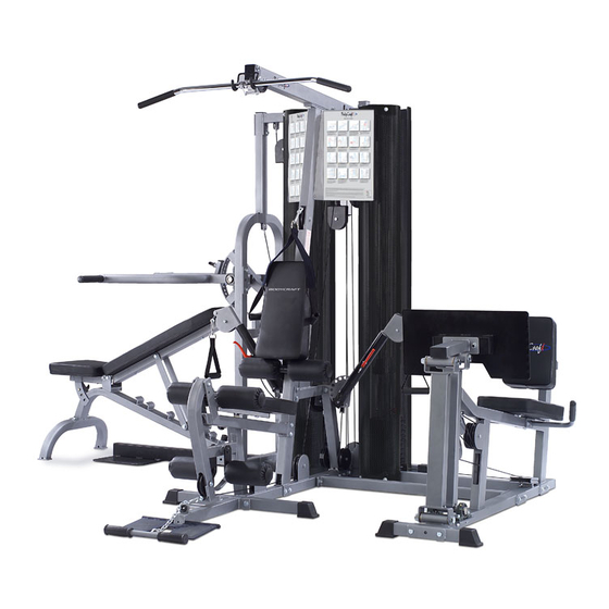
K2 GYM STRENGTH TRAINING SYSTEM
INSTRUCTION MANUAL
QUESTION?
As a quality home gym supplier we are committed to your complete satisfaction. If you have
questions, or find missing or damaged parts, we will guarantee your complete satisfaction through
our authorized dealer service centers or our home office customer service department. Please call
your local dealer for assistance or BodyCraft at 800-990-5556 (9:00 AM - 5:00 PM). Our trained
technicians will provide immediate assistance to you, free of charge.
Bodycraft is a division of Recreation Supply Inc.
P.O. BOX 181
Sunbury, OH 43074
740C
Advertisement
Table of Contents

Related Manuals for BodyCraft K2


Summary of Contents for BodyCraft K2
-
Page 1: Instruction Manual
Please call your local dealer for assistance or BodyCraft at 800-990-5556 (9:00 AM - 5:00 PM). Our trained technicians will provide immediate assistance to you, free of charge. -
Page 2: Before You Begin
Whether your goal is cardiovascular fitness, a shapely, toned body or dramatic muscle size and strength, the K2 GYM will help you achieve the specific results you want. For your safety and benefit, read this manual and the accompanying literature before using the K2 GYM. - Page 3 OVERVIEW 151 158 106A 106A 128A 128A 103A 103A 130A 130A 103A 103A 107A 103A 107A 159 47 148A 103A...
- Page 4 OVERVIEW 100A 100A 107A 107A 107A 107A...
-
Page 5: Parts List
PARTS LIST NO. DESCRIPTION QTY. BASE FRAME REAR STABILIZER REAR UPRIGHT TOP FRAME FRONT UPRIGHT FRONT STABILIZER GUIDE ROD SEAT FRAME CHROMED SEAT ADJUSTER FRONT EXTENDED FRAME FOOT PLATE BACK PAD ADJUSTER LEG EXTENSION ARM CABLE ARM ASSEMBLY CABLE ARM CABLE ARM CONNECTOR GYM TOP GUIDE ROD RETAINER GYM WEIGHT BASE... - Page 6 PARTS LIST NO. DESCRIPTION QTY. AB CRUNCH LINK CHAIN SINGLE HANDLE ANKLE STRAP CLUTCH LEVER OF CABLE ARM SNAP HOOK TOP CABLE AB CABLE CABLE ARM CABLE CONNECTING CABLE BENCH PRESS CABLE ¢¹ BENCH PRESS CABLE ¢º CLUTCH CABLE SELECTOR PIN MAGNETIC PIN METAL CAP NON SLIP...
- Page 7 PARTS LIST NO. DESCRIPTION QTY. 3/4" STEEL BUSHING 107A 1/2" STEEL BUSHING 3/8" BUSHING 107A 1/2" STOPPER 1" STOPPER RUBBER DONUT SPRING KNOB POP PIN (LONGER) POP PIN (SHORTER) ADJ. STOPPER PLASTIC KNOB 5/16" NUT BEARING BEARING BASIN BEARING COVER TOP PLATE BOLT SPRING 1/2"...
-
Page 8: Main Frame Assembly
STEP 1 Main Frame Assembly To ease the assembly process, do NOT tighten bolts until instructed. 1. Attach the Rear Stabilizer (2), to the Base Frame (1) using two 3/8" X 3-1/8" Hex Bolts (130A), four 3/8" Washers (152) and two 3/8" Nylon Nuts (159). -
Page 9: Weight Stack Assembly
STEP 2 Weight Stack Assembly 1. Attach the Gym Weight Base (18) and the Bench Press Weight Base (25) to the Base Frame (1) using two 1/2" X 3-1/4" Hex Bolts (126), four 1/2" Washers (151) and two 1/2" Nuts (158). Insert four plastic Guide Rod Holders (105) into the holes in each Weight Base (18 &... - Page 10 STEP 3 Cable Arm Assembly 1. Attach the Cable Arm Connector (16) to the Front Upright (5) using two 3/8" X 3" Hex Bolts (131), four 3/8" Washers (152) and two 3/8" Nuts (159). Attach the Cable Arm Connector (16) to the pre-threaded holes in the Cable Arm Assembly (14), using two 3/8" X 1"...
- Page 11 STEP 4 Bench Press Arm Assembly We recommend two people for completion of this step. 1. Attach the Chromed Press Adjuster (27) to the Bench Press Arm (23) by inserting the Axle of Bench Press Arm (46). Slide a Pillow Block Bearing (45) onto each end of the Axle of Bench Press Arm (46).
- Page 12 STEP 5 Seat And Back Assembly 1. Attach the Seat Frame (8) to the Front Upright (5), using two 3/8" X 3" Hex Bolts (131), four 3/8" Washers (152) and two 3/8" Nuts (159). Attach the Seat Frame (8) to the Base Frame (1) using one 3/8" X 4-1/2" Hex Bolt (130), two 3/8"...
-
Page 13: Bench Assembly
STEP 6 Bench Assembly 1. Cap two 50mm SQ. End Caps (94) to the Bench Base Frame (19). Attach the Bench Main Frame (22) to Bench Base Frame (19), using two 1/2" Washers (151) and two 1/2" Nuts (158). 2. Attach the Bench Back Support (24) and Bench Seat Adjuster (30) to the Bench Main Frame (22), using two 1/2"... -
Page 14: Top Cable
STEP 7 Top Cable TOP CABLE (57) Ball with hook end Bolt end Assemble cables and pulleys simultaneously. 1. Insert the threaded end of the Top Cable (57) into the slot in the front of the Top Frame (4) as shown in inset T1, and insert a pulley into the slot using one 3/8"... - Page 15 STEP 8 AB Cable AB CABLE (58) Ball end Ball with hook end 1. Route the AB cable (58) through the slot and over the pulley mounted in Front Upright (5) as shown in inset A1. Mount pulley using one 3/8" X 2-1/2" Hex Bolt (133), two 3/8" Washers (152) and one 3/8"...
-
Page 16: Connecting Cable
STEP 9 Connecting Cable Bolt end CONNECTING CABLE (60) Ball end "Please do not use this Connecting Cable if you own the optional leg press. Use the Leg Press Cable found in the Leg Press box." 1. Route the Connecting Cable (60) under the pulley mounted on the Base Frame (1) just behind the weight stack. - Page 17 Single Pulley Block (43) using one 3/8" X 1-3/4" Hex Bolt (134) and one 3/8" Nut as shown in inset K5. Insert the rear side of the Connecting Cable into the slot of the Cable Guide Plate (43A). This cable guide is included to ensure that the Cable Arms Cable does not twist. K1,K9 K2,K8 K4,K6...
- Page 18 STEP 11 Bench Press Cable ¢¹ Bolt end Metal end BENCH PRESS CABLE ¢¹(61) 1. Insert the threaded end of the Bench Press cable (62) into the Top Plate (49) as shown in inset W1. Route the cable up and over the pulley mounted on the Bench Top Guide Rod Retainer (26). Mount the pulley using one 3/8"...
-
Page 19: Bench Press Cable
STEP 12 Bench Press Cable ¢º Bolt end Metal ball end BENCH PRESS CABLE ¢º (62) 1. Screw the threaded end of the Bench Press Cable II into the Single Pulley Block (43) (at least one-third of the threads) as shown in inset S1, then route down and under the pulley mounted on the Adj. - Page 20 STEP 13 Shroud and Poster Plate Assembly Attach the four Shrouds (33) to the Weight Base Frames and Top Guide Rod Retainers, using four 5/16" X 1/2" Hex Bolts (137) and 5/16" Washers (154) on each. Attach the Right and Left Poster Plates (34&35) to the Front Upright (5) using three Female Bolts (138) and three 6 X 12mm Male Nuts (145) on each.
- Page 21 Guide Rods (7). Enjoy many years of a Fit Lifestyle. Thank you for purchasing the K2 GYM. If You have any questions, please call your local BodyCraft dealer or call our customer service department at 800-990-5556...
Need help?
Do you have a question about the K2 and is the answer not in the manual?
Questions and answers