Advertisement
Quick Links
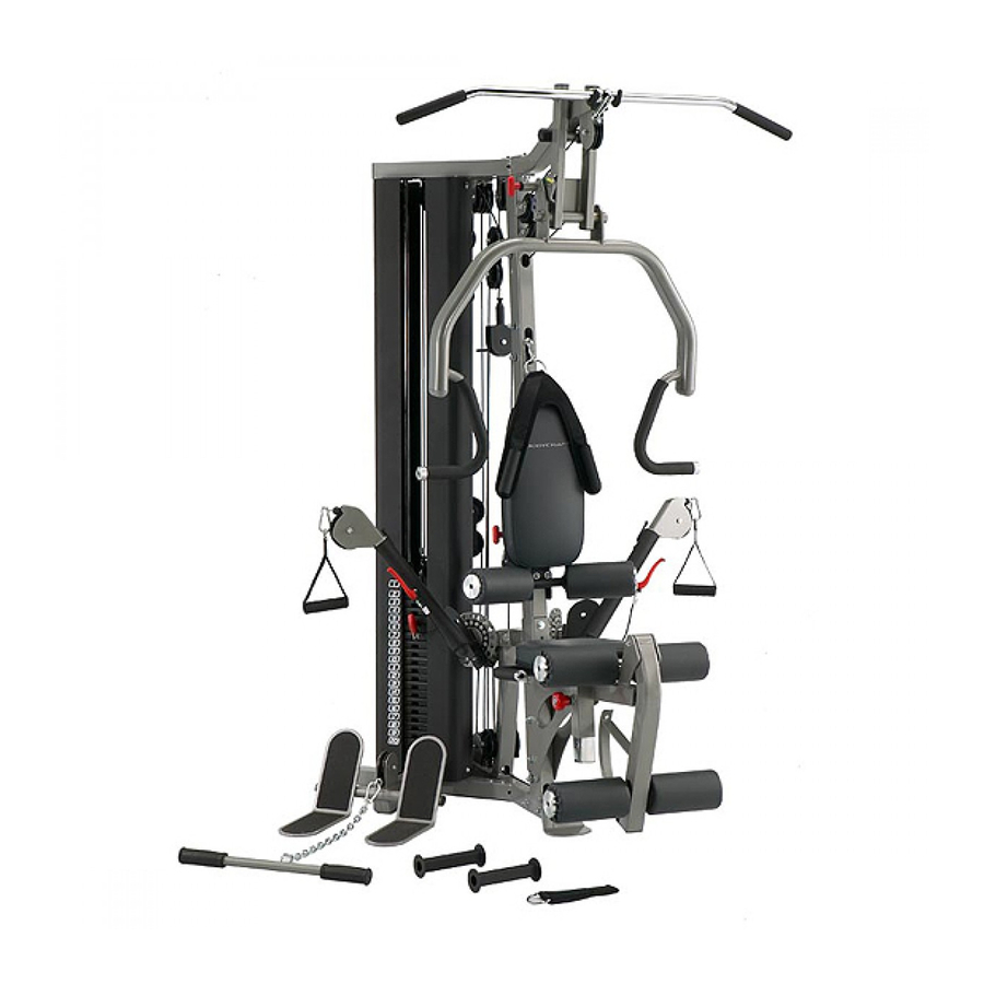
GX STRENGTH TRAINING SYSTEM
INSTRUCTION MANUAL
MODEL BCG-GX
QUESTION?
As a quality home gym supplier we are committed to your complete satisfaction. If you have
questions, or find missing or damaged parts, we will guarantee your complete satisfaction through
our authorized dealer service centers or our home office customer service department. Please call
your local dealer for assistance or BodyCraft at 800-990-5556 (9:00 AM - 5:00 PM). Our trained
technicians will provide immediate assistance to you, free of charge.
Bodycraft is a division of Recreation Supply Inc.
P.O. BOX 181
Sunbury, OH 43074
MZ6881C
Advertisement

Related Manuals for BodyCraft BCG-GX


Summary of Contents for BodyCraft BCG-GX
- Page 1 Please call your local dealer for assistance or BodyCraft at 800-990-5556 (9:00 AM - 5:00 PM). Our trained technicians will provide immediate assistance to you, free of charge.
-
Page 2: Before You Begin
Whether your goal is cardiovascular fitness, a shapely, toned body or dramatic muscle size and strength, the BODYCRAFT GX will help you achieve the specific results you want. For your safety and benefit, read this manual and the accompanying literature before using the BODYCRAFT GX. -
Page 4: Parts List
NO. DESCRIPTION BASE FRAME TOP FRAME FRONT UPRIGHT REAR UPRIGHT GUIDE ROD LEG EXTENSION HANDLE PRESS ARM SEAT ADJ. FRAME SEAT FRAME LEG EXTENSION ARM CABLE ARM ASSEMBLY SEAT BACK ADJUSTER PRESS ARM SUPPORT CABLE ARM SWIVEL CABLE ARM END LEG HOLDER CABLE ARM CONNECTOR ADJUSTABLE PULLEY BLOCK... - Page 5 NO. DESCRIPTION 243L NONSLIP AB CRUNCH STRAP SINGLE HANDLE ANKLE STRAP LINK CLIP SEAT PAD BACK PAD FOAM PAD COVER OF FOAM PAD (all pre-assembled) 1-1/4" X 430mm HAND GRIP 1" X 200mm ROUND HAND GRIP 1" X 95mm HAND GRIP (all pre-assembled) LAT BAR HOLDER COVER (all pre-assembled) 1-1/4"...
- Page 6 NO. DESCRIPTION 5/8" X 5-1/2" HEX BOLT 3/8" X 4-3/4" HEX BOLT 3/8" X 4" HEX BOLT 3/8" X 3-1/8" HEX BOLT 3/8" X 3-1/4" HEX BOLT 3/8" X 3" HEX BOLT 3/8" X 2-3/4" HEX BOLT 3/8" X 1-3/4" HEX BOLT 3/8"...
- Page 7 STEP 1 ASSEMBLE BASE FRAME To ease the assembly process, Do Not tighten bolts until instructed. 1. Attach Front Upright (3) to Base Frame (1), using two 3/8" X 3" Hex Bolts (99), four 3/8" Washers (116) and two 3/8" Nuts (116).
- Page 8 STEP 2 ASSEMBLE TOP FRAME 1. Insert Guide Rod Mount (129) onto the Guide Rods (5), then attach to Top Frame (2) using two 5/16" X 5/8" Botton Head Bolts (108). Tighten 5/16" X 1/4" Set Screws (112) into the Guide Rods (5). Place Top Frame (2) on top, making sure to insert the Guide Rods (5) and Rear Upright (4).
- Page 9 STEP 3 ASSEMBLE CABLE ARM ASSEMBLY Remember to keep all BOLTS loose to ensure the holes will align easily. 1. Attach Cable Arm Assembly (11) to Cable Arm Connector (17), using two 3/8" X 1" Hex Bolts (103) and two 3/8" Washers (116) then attach Cable Arm Connector (17) to Front Upright (3), using two 3/8"...
- Page 10 STEP 4 ASSEMBLE PRESS STATION 1. Attach Press Arm Support (13) to the Top Frame (2) by aligning the holes and inserting the 5/8" X 5-1/2" Hex Bolt (95) with two 5/8" Washers (115) and one 5/8" Nylon Nut (123). 2.
- Page 11 STEP 5 ASSEMBLE SEAT FRAME AND SEAT & BACK PAD 1. Attach Seat Frame (9) to Front Upright (3), using three 3/8" X 3" Hex Bolts (99) six 3/8" Washers (116) and three 3/8" Nylon Nuts (124). 2. Attach Seat Back Adjuster (12) to Front Upright (3), using one 3/8" X 3" Hex Bolt (99), two 3/8" Washers (116) and one 3/8"...
- Page 12 STEP 6 INSTALL TOP CABLE Pulleys T3 and T5 are mounted to either side of the steel tab. Do not mount both pulleys to one side. Assemble cables and pulleys simultaneously 1. Grab the threaded end of the Top Cable (87). Run the cable over a Pulley T1 you will mount at the front of the Top Frame (2) using one 3/8"...
- Page 13 STEP 6 INSTALL TOP CABLE...
- Page 14 STEP 7 INSTALL AB CABLE 1. Run the steel ball end of the Ab Cable (88) through the slot in the Front Upright (3) and attach two pulleys in the slot as shown in Fig. A1, using two 3/8" X 3" Hex Bolts (99), four 3/8" Washers (116), four 3/8" ID Bushings (77), and two 3/8"...
- Page 15 STEP 8 INSTALL LOWER CABLE 1. Route the steel ball end of the Lower cable (89) under Pulley L1 mounted at the front of the Low Pull Station using one 3/8" X 1-3/4" Hex Bolt (101) and one 3/8" Nylon Nut (124). 2.
- Page 16 STEP 9 INSTALL CONNECT CABLE 1. Hook the steel ball end of the Connect Cable (90) to the receptor C1 welded to the Base Frame (1). Route the cable up and over Pulley C2 mounted to the bottom of the Double Pulley Block (19) using one 3/8"...
- Page 17 STEP 10 INSTALL CABLE ARM CABLE 1. The Cable Arm Cable (91) is already run through the Cable Arms (14). Mount Pulleys P3 and P7, along with their Pulley Guide Brackets (32) to the Cable Arm Assembly (11) as shown using one 3/8" X 1-3/4"...
- Page 18 STEP 11 INSTALL WEIGHT STACK SHROUDS ASSEMBLY IS COMPLETE! Tighten all bolts, starting with main frame bolts on the base, and work way to top. 1. Attach Weight Stack Shroud (26) and Weight Stack Shroud with Number (26A) to the tabs welded on Base Frame (1) and Top Frame (2) as shown, using four 5/16"...
- Page 19 STEP 12 INSTALL ACCESSORIES 1. Attach Lat Bar (29), Curl Bar (30), Single Handle (43), to the GX Strength Training System.
- Page 20 The Cable Adjustment of GX Strength Training System a. The Cables should be tightened to the point just before the Top Plate lifts off the stack. In other words, if the Top Plate is not resting on the stack, you will need to add length, or, if there is slack in the cables, you will need to shorten the cables.
- Page 21 Guide Rods (5). Enjoy many years of a Fit Lifestyle. Thank you for purchasing the BodyCraft Fid Bench. If you have any questions, please call your local BodyCraft dealer, call our customer service department at 800-990-5556 or at...
Need help?
Do you have a question about the BCG-GX and is the answer not in the manual?
Questions and answers