Advertisement
Quick Links
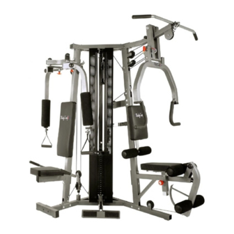
GALENA PRO STRENGTH TRAINING SYSTEM
INSTRUCTION MANUAL
MODEL BCG 446-P
QUESTION?
As a quality home gym supplier we are committed to your complete satisfaction. If you have
questions, or find missing or damaged parts, we will guarantee your complete satisfaction through
our authorized dealer service centers or our home office customer service department. Please call
your local dealer for assistance or BodyCraft at 800-990-5556 (9:00 AM - 5:00 PM). Our trained
technicians will provide immediate assistance to you, free of charge.
Bodycraft is a division of Recreation Supply Inc.
P.O. BOX 181
Sunbury, OH 43074
6850
Advertisement

Related Manuals for BodyCraft BCG 446-P


Summary of Contents for BodyCraft BCG 446-P
- Page 1 Please call your local dealer for assistance or BodyCraft at 800-990-5556 (9:00 AM - 5:00 PM). Our trained technicians will provide immediate assistance to you, free of charge.
-
Page 2: Before You Begin
3. Inspect and tighten all parts before every use. Replace any worn parts immediately. Failure to do so may result in serious injury. 4. Keep children away from the BODYCRAFT GALENA PRO at all times. 5. Keep your hands away from cables and pulleys during operation. - Page 3 90 85 49 49 84 90 81 90...
-
Page 4: Parts List
PARTS LIST DESCRIPTION BASE FRAME PEC DEC UPRIGHT PRESS UPRIGHT CENTER UPRIGHT GUIDE ROD (10) STACK SPACER WEIGHT PLATE TOP PLATE SELECTOR ROD TOP FRAME AB PULLEY TUBE PEC DEC PULLEY BRACKET PEC DEC SUPPORT ADJ. CAM LEFT PEC DEC ARM BRACKET (pre-assembled) RIGHT PEC DEC ARM BRACKET (pre-assembled) - Page 5 PARTS LIST DESCRIPTION RUBBER STOPPER (pre-assembled) POP PIN RED POP PIN (pre-assembled) (39) (40) (40a) (41) (42) KNOB SELECT PIN CLIP LINK TOP CABLE (43) (44) (49) (50) PEC DEC CABLE LOWER CABLE PULLEY NONSLIP (45a) PRESS BACK PAD(SMALLER) PRESS SEAT PAD(LARGER) PEC DEC BACK PAD(LARGER) (46a) PEC DEC SEAT PAD(SMALLER)
- Page 6 PARTS LIST DESCRIPTION 7/16" X 1-1/2" TOP PLATE BOLT 5/8" X 7-1/2" HEX HEAD BOLT 1/2" X 4-1/4" HEX HEAD BOLT (70) (84) (85) 1/2" X 3-1/2" HEX HEAD BOLT 1/2" X 3-1/4" HEX HEAD BOLT 3/8" X 1-3/4" HEX HRAD BOLT (ALL) 3/8"...
- Page 7 STEP 1 ASSEMBLE BASE FRAME 1. Attach PEC DEC UPRIGHT(2) to BASE FRAME(1) using two 3/8" X 2-3/4" HEX HEAD BOLTS(79), four 3/8" WASHERS(90) and two 3/8" NYLON NUTS(87). 2. Attach PRESS UPRIGHT(3) to BASE FRAME(1) using two 3/8" X 2-3/4" HEX HEAD BOLTS(79), four 3/8"...
-
Page 8: Step 2 Assemble Weight Stack
STEP 2 ASSEMBLE WEIGHT STACK 1. Insert 1" ID BUSHING(64) into the holes on BASE FRAME(1), insert GUIDE ROD(5) to 1" ID BUSHING(64) then slide STACK SPACER(6) and RUBBER CUSHION(38) onto GUIDE ROD(5). 2. Attach TOP PLATE(8) to SELECTOR ROD(9) using 7/16" X 1-1/2" TOP PLATE BOLT(70). - Page 9 STEP 3 ASSEMBLE TOP FRAME 1. Insert two 1" ID BUSHINGS(64) into the holes on TOP FRAME(10), then place TOP FRAME(10) down onto GUIDE RODS(5) and CENTER UPRIGHT(4). 2. Attach TOP FRAME(10) to CENTER UPRIGHT(4) using three 3/8" X 3/4" HEX HEAD BOLTS(84) and three 3/8"...
- Page 10 STEP 4 ASSEMBLE PEC DEC STATION 1. Attach PEC DEC SUPPORT(13) and PEC DEC PULLEY BRACKET(12) to PEC DEC UPRIGHT(2) using two 1/2" X 4-1/4" HEX HEAD BOLTS(72), two 1/2" WASHERS(89) and two 1/2" NYLON NUTS(86). 2. Slide ADJ. CAM(14) onto the axle of RIGHT PEC DEC ARM BRACKET(16). Then thread the axle of RIGHT PEC DEC ARM BRACKET(16) through the hole on PEC DEC SUPPORT(13) and attach using 1/2"...
- Page 11 STEP 5 ASSEMBLE PRESS STATION 1. Attach the PRESS ARM SUPPORT(19a) to the TOP FRAME(10) by aligning the holes and inserting the 5/8" x 7-1/2" HEX BOLT(71) with two 5/8" WASHERS(88), and one 5/8" NYLON NUT(85). Plug the openings in the TOP FRAME(10) and top of the PRESS ARM SUPPORT(19a) with 50mm SQ.
- Page 12 STEP 6 INSTALL TOP CABLE Insert the threaded end of the TOP CABLE(45a) into the pulley slot in the front of the TOP FRAME(10) over pulley T1 and back to pulley T2 on the PRESS UPRIGHT(3). Route cable over and around Pulley T2, exiting from bottom. Then route cable over top of Pulley T3 [you will mount two pulleys side-by-side here.
- Page 13 STEP 7 INSTALL PEC DEC CABLE Loosely attach pulley P2 and P4 and CABLE GUIDE(18) to PEC DEC PULLEY BRACKET(12). Insert one end of PEC DEC CABLE(46a) into receiver on right ADJ. CAM(14) as shown and route cable over pulley, behind PEC DEC UPRIGHT(2), over pulley and insert opposite end into receive on left ADJ.
- Page 14 STEP 8 INSTALL AB CABLE DO NOT USE THIS CABLE IF YOU PURCHASED THE OPTIONAL LEG PRESS. THE LEG PRESS CABLE IS INSTALLED HERE INSTEAD. REFER TO THE LEG PRESS MANUAL. Run the eyelet end of the AB CABLE(94a) through the slot in the FRONT UPRIGHT(3) and attach a pulley inside the slot as shown in fig.
- Page 15 STEP 9 INSTALL LOWER CABLE Insert ball end of LOWER CABLE(48a) using 3/8" x 1-3/4" HEX HEAD BOLT(82) and 3/8" NYLON NUT(87) and route cable under pulley L1, L2, up and around pulley L3, down and around pulley L4, under pulley L5 then attach the eyelet end under the cam of LEG EXETESION(23) through the "U"...
-
Page 16: Step 10 Install Accessories
STEP 10 INSTALL ACCESSORIES 1. Attach SMALLER PRESS BACK PAD(51) to CHROME BACK ADJUSTER(30a), using two 3/8" X 1-3/4" BOLTS(75) and two 3/8" WASHERS(90). Insert ROLLER BAR(24) through the bottom of CHROME BACK ADJUSTER(30a), moisten FOAM PAD(60) with water and slide onto the ROLLER BAR(24). Attach 1" ROUND END PLUG(37) to both end of ROLLER BAR(24). - Page 17 STEP 11 INSTALL OPTIONAL WEIGHT STACK GUARDS If you did not purchase the optional WEIGHT STACK GUARDS, please skip this step. Attach WEIGHT STACK GUARD(96) to BASE FRAME(1) and TOP FRAME(10) using 5/16" HEX HEAD BOLT(96a) and 5/16" WASHER(96b). (96) OPTIONAL WEIGHT STACK GUARDS...
- Page 18 Step 12 The Cable Adjustment a. The Cables should be tightened to the point just before the Top Plate lifts off the stack. In other words, if the Top Plate is not resting on the stack, you will need to add length, or, if there is slack in the cables, you will need to shorten the cables.
- Page 19 Guide Rods(5). Enjoy many years of a Fit Lifestyle. Thank you for purchasing the Bodycraft Galena Pro Home Gym. If you have any questions, please call your local BodyCraft dealer, call our customer service department at 800-990-5556 or at http://www.bodycraft.com.
Need help?
Do you have a question about the BCG 446-P and is the answer not in the manual?
Questions and answers