Table of Contents
Advertisement
Quick Links
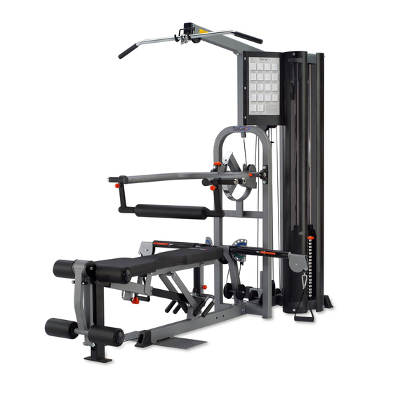
K1 GYM STRENGTH TRAINING SYSTEM
INSTRUCTION MANUAL
QUESTION?
As a quality home gym supplier we are committed to your complete satisfaction. If you have
questions, or find missing or damaged parts, we will guarantee your complete satisfaction through
our authorized dealer service centers or our home office customer service department. Please call
your local dealer for assistance or BodyCraft at 800-990-5556 (9:00 AM - 5:00 PM). Our trained
technicians will provide immediate assistance to you, free of charge.
Bodycraft is a division of Recreation Supply Inc.
P.O. BOX 181
Sunbury, OH 43074
MA4109
Advertisement
Table of Contents

Related Manuals for BodyCraft K1


Summary of Contents for BodyCraft K1
- Page 1 Please call your local dealer for assistance or BodyCraft at 800-990-5556 (9:00 AM - 5:00 PM). Our trained technicians will provide immediate assistance to you, free of charge.
-
Page 2: Before You Begin
Whether your goal is cardiovascular fitness, a shapely, toned body or dramatic muscle size and strength, the K1 GYM will help you achieve the specific results you want. For your safety and benefit, read this manual and the accompanying literature before using the K1 GYM. - Page 3 EXPOLDED VIEW 114 120 44 55 65 129 108 112 137 65 28 119 127 119 118 127 134...
-
Page 4: Table Of Contents
PARTS LIST NO. DESCRIPTION QTY. BASE FRAME REAR UPRIGHT TOP FRAME REAR STABILIZER BENCH PRESS UPRIGHT BENCH PRESS ARM SEAT SUPPORT GUIDE ROD BACK PAD SUPPORT SEAT SLIDER CHROMED CAM ASSEMBLY CABLE ARM ASSEMBLY TOP GUIDE ROD RETAINER HANDLE CABLE ARM SQUAT HANDLE LEG EXTENSION CABLE ARM LEG EXTENSION ARM... - Page 5 PARTS LIST NO. DESCRIPTION QTY. TOP CABLE LEG EXTENSION CABLE CONNECTING CABLE CABLE ARM CABLE CLUTCH CABLE MAGNETIC SELECTOR PIN SEAT PAD BACK PAD FOAM PAD COVER OF FOAM PAD FOAM OF SQUAT HANDLE COVER OF FOAM OF SQUAT HANDLE METAL CAP 115mm PULLEY 90mm PULLEY...
- Page 6 PARTS LIST NO. DESCRIPTION QTY. 1/2" X 5-1/4" HEX BOLT 1/2" X 3-1/2" HEX BOLT 1/2" X 3-1/4" HEX BOLT 1/2" X 3" HEX BOLT 1/2" X 1" HEX THREADED BOLT 3/8" X 5-3/4" HEX BOLT 3/8" X 3-1/8" HEX BOLT 3/8"...
-
Page 7: Base Frame
STEP 1 Base Frame Assembly To ease the assembly process, do NOT tighten bolts until instructed. 1. Attach the Rear Stabilizer (4) to the Base Frame (1) using two 1/2" X 3-1/4" Hex Bolts (108), four 1/2" Washers (129) and two 1/2" Nylon Nuts (137). Attach the 50 X 75mm End Cap (69) to the front of the Base Frame (1) and attach two 50 X 75mm End Caps (68) to the Rear Stabilizer (4). -
Page 8: Bench Press Arm
STEP 2 Cable Arm and Bench Press Assembly We recommend two people for completion of this step. 1. Attach the Cable Arm Assembly (12) to the Bench Press Upright (5), using two 3/8" X 3- 1/8" Hex Bolts (112), four 3/8" Washers (130) and two 3/8" Nylon Nuts (138). Remember to keep all bolts loose to ensure the holes will align easily. -
Page 9: Seat Support 1
STEP 3 Seat and Leg Extension Assembly 1. Slide the Seat Slider (10) onto the Seat Support (7) and then attach the Handle Set (14) and Seat Support (7) to the Base Frame (1), using two 1/2" X 3-1/4" Hex Bolts (108), four 1/2" Washers (129) and two 1/2"... -
Page 10: Guide Rod
STEP 4 Top Cable Assembly TOP CABLE (52) Bolt end Ball with hook end Assemble cables and pulleys simultaneously 1. Start by inserting the threaded end of the Top Cable (52) into the slot in the front of the Top Frame (3) as shown in inset T1. -
Page 11: Cable Arm
STEP 5 Install Leg Extension Cable LEG EXTENSION CABLE (53) Eyelet end Ball end 1. With the ball end of the cable to the outside (under weight stack), mount pulley L1 to the base frame directly behind the weight stack using one 3/8" X 1-3/4" Hex Bolt (118) and one 3/8"... - Page 12 STEP 6 Install Connecting Cable CONNECTING CABLE (54) Threaded Bolt end Threaded Bolt end 1. Attach pulley on bracket welded on Base Frame (1) with Pulley Guard (28) and Metal Tab W/Screw (27), using one 3/8" X 2" Hex Bolt (117), one 3/8" X 1" Hex Threaded Bolt (119) and two 3/8" Nylon Nuts (138) as shown inset L6.
- Page 13 Ball end Ball end The Cable Arms and Cable are preassembled. Inset K1, K11 is there just to show you the internal components in the unlikely event you have a future internal problem. You need to complete the routing of the Cable Arms Cable (55) to the rest of the machine.
-
Page 14: Floating Pulley Block
Step 8 The Cable Adjustment a. The Cables should be tightened to the point just before the Top Plate lifts off the stack. In other words, if the Top Plate is not resting on the stack, you will need to add length, or, if there is slack in the cables, you will need to shorten the cables. -
Page 15: Shroud
STEP 9 Shroud and Poster Plate Assembly 1. Attach the two Shrouds (40) to the Base Frame (1) and Top Guide Rod Retainer (13) using four 5/16" X 1/2" Hex Bolts (120) and four 5/16" Washers (131) on each. 2. Attach the Poster Plate (39) to the Bench Press Upright (5) using three 5/16" X 5/8" Inner Screws (124) and three 5/16" Washers (131). -
Page 16: Magnetic Selector Pin 1
Guide Rods (8). Enjoy many years of a Fit Lifestyle. Thank you for purchasing the K1 Gym. If You have any questions, please call your local BodyCraft dealer or call our customer service department at 800-990-5556...
Need help?
Do you have a question about the K1 and is the answer not in the manual?
Questions and answers