Table of Contents
Advertisement
Quick Links
Advertisement
Table of Contents

Related Manuals for Mellanox Technologies Grid Director 4036


Summary of Contents for Mellanox Technologies Grid Director 4036
- Page 1 Grid Director 4036/2036 Installation Manual DOC-00467 A09 www.mellanox.com...
- Page 2 Mellanox. Except as permitted by the applicable license, no part of this document may be reproduced, stored in a retrieval system, or transmitted in any form or by any means without the express written consent of Mellanox.
-
Page 3: Table Of Contents
Contents Contents Preface ..............................7 Introduction ............................. 9 4036/2036 Switch Overview ....................9 4036/2036 Switch Main Features ..................10 Management ......................... 10 Unpacking ............................11 Package Contents ........................ 11 Unpacking the 4036/2036 Switch ..................11 Rail Kit (KIT-00008) ......................13 Multipurpose (Mng) Console Cable Kit ................. - Page 4 Contents 6.1.1 Cooling ........................31 Required Tools ........................31 Site Planning ......................... 32 6.3.1 Rack and Clearance Requirements ................ 32 6.3.2 Site Environment Specification ................32 6.3.3 Power Requirements ....................32 6.3.4 Site Preparation Checklist ..................33 Measuring the Distance between Mounting Rails ..............33 Assembling and Mounting the Rail ..................
- Page 5 Contents List of Figures Figure 1: 4036/2036 Front View ......................9 Figure 2: 4036/2036 Rear View ....................... 9 Figure 3: 4036/2036 Cardboard Package (Open) - Standard ............... 12 Figure 4: Removing the 4036/2036 Switch from the Cardboard Package ..........13 Figure 5: Fixed Rail (KIT-00008) ......................
- Page 6 Contents Figure 43: Installing a Cabling Guide Bracket ..................51 Figure 44: Installing a Cabling Guide Bracket (sliding rail) ..............51 Figure 45: Cable Management ......................52 Figure 46: Cabling ..........................52 Figure 47: 4036/2036 Cardboard Package (Open) - Standard ............. 59 Figure 48: 4036/2036 –...
-
Page 7: Preface
Grid Director 4036/2036 Installation Manual Preface About this Manual This manual provides installation instructions for the Voltaire high-bandwidth, low-latency scalable 36-port InfiniBand 4036 QDR and 2036 DDR chassis. It includes the product specifications, unpacking and installation information, unit power up, and initiation and troubleshooting procedures. - Page 8 Typography The following table describes typographical conventions in Mellanox documentation. All terms refer to isolated terms within body text or regular table text unless otherwise mentioned in the Notes column.
-
Page 9: Introduction
Grid Director 4036/2036 Installation Manual Introduction 4036/2036 Switch Overview The Mellanox Grid Director 4036/2036 is a high performance, low latency and fully non-blocking InfiniBand switch for high performance clusters. Delivering 2.88 Tbps of non-blocking bandwidth with less than 100 nanoseconds of latency (port-to-port), I/O bottlenecks are removed making applications operate at maximum efficiency. -
Page 10: 4036/2036 Switch Main Features
Built-in high availability Management The Grid Director 4036/2036 includes smart device management that provides a simple interface for deploying, troubleshooting, maintaining and upgrading the switch. With a simple to use CLI interface, routine tasks such as monitoring the switch’s operation or upgrading software and firmware are made simple. -
Page 11: Unpacking
Grid Director 4036/2036 Installation Manual Unpacking Package Contents The 4036/2036 switch is supplied in a cardboard box. The switch is delivered with either one or two pre-installed hot-swappable power supplies (according to configuration) and one hot-swappable fan unit. Additional components include: ... -
Page 12: Figure 3: 4036/2036 Cardboard Package (Open) - Standard
Unpacking Figure 3: 4036/2036 Cardboard Package (Open) - Standard NOTE: Keep the original packing materials; they will be needed if: The product needs to be moved. For example if it is staged at one location before being delivered at the production site. ... -
Page 13: Rail Kit (Kit-00008)
Grid Director 4036/2036 Installation Manual 5. Carefully remove the 4036/2036 switch. Use the dedicated niche to lift the switch, as shown in the following figure. Figure 4: Removing the 4036/2036 Switch from the Cardboard Package 6. Remove the protective antistatic bag from the 4036/2036 switch. -
Page 14: Multipurpose (Mng) Console Cable Kit
Unpacking Figure 5: Fixed Rail (KIT-00008) Multipurpose (Mng) Console Cable Kit The multipurpose console kit (Mng) contains: RJ45 to RJ45 cable A RJ45 to DB-9 cross-adaptor for RS-232 console connection (CLI). (The DB-9 adaptor has a number 26 printed on it. This means that pins 2 and 6 are crossed). ... -
Page 15: Figure 6: Packing The 4036/2036 Switch
Grid Director 4036/2036 Installation Manual Figure 6: Packing the 4036/2036 Switch 6. Insert the switch into the cardboard box and place it on the bottom foam. 7. Place the top foam on top of the switch. 8. Slide the rail kit box in the dedicated niche alongside of the switch, as shown in illustration in Unpacking the Switch (on page 59). -
Page 16: Getting Started
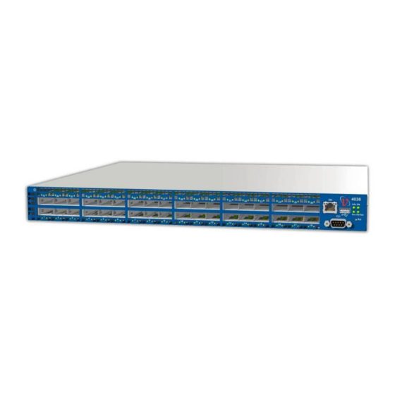
Getting Started Getting Started Front Panel Description This section details the front panel 4036/2036 chassis. Figure 7: 4036/2036 Front Panel 1. Swappable power supply modules 2. LEDs: System power Info LED Fan unit Power supply 3. -
Page 17: Rear Panel Description
Grid Director 4036/2036 Installation Manual Component 4036 /2036 No. Function of components Reset Button When pressed for more than 1 second, resets the entire unit. System Power – Chassis power OK LED - ON/OFF LEDs (Status Indicators) Info LED – User-defined LED for management use. Sets the Info LED on a desired module. -
Page 18: Table 2: Rear Panel Components
Getting Started Table 2: Rear Panel Components Component Function InfiniBand Port 4X QSFP InfiniBand connectors for passive copper cables, active copper cables, Connector active optical cables, and connect optical cables. InfiniBand Port Indicates the physical and logical status of each InfiniBand port. (2 LEDs per Indicators (LEDs) port) RS232 serial... -
Page 19: Product Options
(where the 4036/2036 is serving as core switch) or as a standalone managed unit in smaller clusters. InfiniBand Clusters Using the 4036/2036 Switch The Grid Director 4036/2036 switch is designed as a standalone unit or as a building block for larger clusters. -
Page 20: Figure 8: Infiniband Cluster Using 4036 Switch Single-Hop Configuration
Product Options The following figures show a simple 36-server single-hop non-blocking configuration using a single 4036/2036 switch. Figure 8: InfiniBand Cluster Using 4036 Switch Single-hop Configuration Figure 9: InfiniBand Cluster Using 2036 Switch Single-hop Configuration The following figures show a triple-hop non-blocking configuration, based on multiple 4036/2036 switches functioning as the cluster building blocks. - Page 21 Grid Director 4036/2036 Installation Manual...
-
Page 22: Ordering Information
VLT-30114 Grid Director 2036 1PS 2036 1U 36 port QDR Switch, front-to-back cooling, single PS VLT-30111 Grid Director 4036 2PS 4036 1U 36 port QDR Switch, front-to-back cooling, dual PS VLT-30011 Grid Director 4036 2PS 4036 1U 36 port QDR Switch, back-to-front cooling,... -
Page 23: Table 4: 4036/2036 Module Ordering Information
Grid Director 4036/2036 Installation Manual Number Name Description VLT-30015 Grid Director 4036 1PS 4036 1U 36 port QDR Switch, back-to-front cooling, single PS Table 4: 4036/2036 Module Ordering Information Number Name Description VLT-30029-F PS-36 AC FRU PS-36 AC, FRU VLT-30030-F... -
Page 24: Technical Specifications And Certifications
Technical Specifications and Certifications Technical Specifications and Certifications 4036/2036 Switch Technical Specifications Table 6: 4036/2036 Switch Technical Data Features Details Grid Director 19-inch front or rear rack mountable chassis, height: 1U, depth: 15" 4036/2036 - 4036 with Quad Data Rate (QDR) 40 Gbps ports General ... -
Page 25: Power Specifications - Power Supply Module
Grid Director 4036/2036 Installation Manual Features Details Environmental Operating Temperature: 32°F to 113°F (0°C to 45°C) Humidity: 15% to 80%, non-condensing Altitude: 0 to 9843 ft (3000m) Storage Temperature: -13°F to 185°F (-25°C to +85°C) ... -
Page 26: Certifications
Technical Specifications and Certifications Certifications Safety cTUVus (USA/CAN); CE according to EN 60950-1 First Ed. MET Labs (NRTL) CE according to EN 69950-1 CSA C22.2 60950-1 S-Mark Argentina CB Certificate and report, according to IEC 60950-1 First Ed. ... -
Page 27: Gost-R Certification
Directive 99/5/EEC, the EMC Directive 89/336/EEC, and of the Low Voltage Directive 73/23/EEC. 5.5.2 Hazardous Substances (RoHS 5) Compliance Declaration Mellanox products comply with the RoHS directive under the exemption (RoHS 5) of lead in solders for servers, storage and telecommunication infrastructure. -
Page 28: Label(S)
Technical Specifications and Certifications Label(s) The 4036/2036 label (example) below shows all safety and EMC text and logos. Figure 11: 4036 Label (Example) Figure 12: 2036 Label (Example) -
Page 29: Shock And Vibration
Grid Director 4036/2036 Installation Manual Shock and Vibration Prepare the 4036/2036 switch to ship in a rack by carefully following the rail kit installation and instructions, as detailed in Chapter 6 (on page 31). The 4036/2036 is susceptible to shock and vibration damage if the rail kit installation instructions are not followed precisely. -
Page 30: Export Information
Technical Specifications and Certifications 5.11 Export Information CTP (Composite Theoretical Performance) is a calculation measured in MTOPS (millions of theoretical operations per second). The 460EX/460GT contain a 440H6 core (not a 460 core; it is called 460 to distinguish it as a 90 nm core). -
Page 31: Hardware Installation
The following materials and tools are required for mounting the 4036/2036 chassis into a rack. Table 11: Materials and Tools Required Quantity Description Flat-blade screwdriver Phillips screwdriver Measuring tape Floating clip nuts (not provided by Mellanox) Phillips screws (not provided by Mellanox) -
Page 32: Site Planning
Hardware Installation Site Planning Planning the proper location and layout of your equipment rack or wiring closet is essential for successful 4036/2036 switch operation. Equipment placed too close together or in an inadequately ventilated area can cause overheating of the system. In addition, poor equipment placement can render system panels inaccessible and difficult to maintain. -
Page 33: Site Preparation Checklist
Grid Director 4036/2036 Installation Manual 6.3.4 Site Preparation Checklist To help prepare your site for installing the Grid Director 4036/2036 chassis, use the following checklist. Table 12: Site Preparation Checklist Task Prepared by Date Notes Environmental requirements Locate power sources... -
Page 34: Table 13: Rail Kit (P/N Kit-00008) Detailed Part List
Hardware Installation Table 13: Rail Kit (P/N KIT-00008) Detailed Part List Item Illustration 2 x short bracket 290000169 2 x Mounting MEC-0055 Front side of the chassis Rear side of the chassis 14 x Pan Head FAS-0004 Philips Screw, 8-32 x 1/4" with tooth lock washer and nylon patch... -
Page 35: Option 1
Grid Director 4036/2036 Installation Manual 6.5.2 Option 1 The rail assembly described in this section enables front-to-rear switch installation within the rack, meaning that the front of the switch faces the front of the rack. The front of the switch is recessed 5 inches from the vertical rail of the rack to allow connecting the power cords from the front side of the rack. -
Page 36: Figure 14: Mounting The Long Bracket
Hardware Installation Mount the long bracket at the front of the chassis using three 8-32x1/4" pan head Philips screws. Important: Left and right long brackets are different. Make sure that you are using the correct bracket. The mounting ear at the end of the bracket should face out. Figure 14: Mounting the long bracket 2. -
Page 37: Figure 17: Installing The Clip Nuts And Placing The Power Cord
Measuring the Distance between Mounting Rails (on page 33). Note: Rack clip nuts are not provided by Mellanox. Figure 17: Installing the clip nuts and placing the power cord 6. Place the power cords with the female connector facing the front of the rack (or the switch) with approximately 10"... -
Page 38: Figure 19: Power Cord Over The Long Bracket
Hardware Installation 8. Place the power cords over the indentation of the long brackets. Figure 19: Power cord over the long bracket 9. Secure each power cord with a cable tie wrap so that you can still adjust the length of the cord if required. -
Page 39: Figure 22: Secure The Long Brackets To The Rack Rail
Grid Director 4036/2036 Installation Manual 12. Fasten the long brackets to the rack’s vertical rails using two screws per bracket and tighten them. Figure 22: Secure the long brackets to the rack rail 13. Mount a short bracket from the inner side of the mounting bar and fasten it using two 8-32x1/4"... -
Page 40: Figure 24: Adjusting The Short Bracket
Hardware Installation 14. Adjust the short brackets snuggly onto the rack’s vertical rail using the adjusting holes (make sure that the rail is perfectly aligned by using the same U as used in the front of the rack). Figure 24: Adjusting the short bracket 15. -
Page 41: Figure 27: Switch Mounted In A Rack - Rack Front View
Grid Director 4036/2036 Installation Manual Result – Rack front view Figure 27: Switch mounted in a rack – Rack front view... -
Page 42: Option 2
Hardware Installation 6.5.3 Option 2 The rail assembly described in this section enables rear-to-front switch installation within the rack, meaning that the rear of the switch (InfiniBand connector side) faces the front of the rack. This rear-to-front chassis installation is in-line with the vertical front rails of the rack. Figure 28: 4036/2036 –... -
Page 43: Figure 29: Mounting The Short Bracket
Grid Director 4036/2036 Installation Manual On each side of the chassis, mount the short brackets on the rear side of the switch (InfiniBand port side) using three 8-32x1/4" pan head Philips screws, as shown on the picture. Figure 29: Mounting the short bracket 2. -
Page 44: Figure 31: Positioning And Aligning The Mounting Bar And Long Bracket
Hardware Installation Note: Make sure that the distance is between 0.5" to 1" greater than the distance you measured between the two vertical rack rails to allow adjustment at a later stage. Figure 31: Positioning and aligning the mounting bar and long bracket Total distance = rack measurements + 0.5 to 1"... -
Page 45: Figure 33: Placing The Clip Nuts On The Vertical Rack Rails
Figure 34: Insert the switch into the rack 7. Align the short bracket holes with the rack holes of the correct U level and secure them using two rack screws on each side (not provided by Mellanox). Figure 35: Secure the rack screws... -
Page 46: Figure 36: Installing The Long Bracket
Hardware Installation On each side, align the long bracket holes with the rack holes of the correct U level and secure them using two rack screws (not provided by Mellanox) and two rail screws. Figure 36: Installing the long bracket 9. -
Page 47: 4036/2036 Switch Power Up
Once the 4036/2036 chassis is secure within the rack, electrical cables from the power distribution source can be fitted in preparation for connection. Two power cords are supplied by Mellanox, one per power supply unit. To power up the 4036/2036 switch: 1. -
Page 48: Field Replaceable Units
Hardware Installation Field Replaceable Units 6.7.1 Fan Unit The 4036/2036 switch has a hot swappable Fan Unit with three fans that are used to maintain proper cooling, as shown. In normal operation, the two fans work at 50% utilization. In case of fan failure or high temperature detection, the fans go into Turbo mode. In case of fan failure, the fan drawer LED and the PS/FAN LED on the rear panel blink. -
Page 49: Figure 41: Replacing The Power Supply
Grid Director 4036/2036 Installation Manual When removing a power supply from the chassis, the other supply can power the entire chassis. Figure 41: Replacing the Power Supply NOTE: Power supplies can be replaced while the power is ON. However, it is recommended to turn the power OFF before replacing the power supply. -
Page 50: Cabling
Cabling Cabling This chapter provides details on the 4036/2036 switch cable guide brackets installation and cable management. Cabling Guide Bracket Installation NOTES: Selecting the optimal InfiniBand cable length depends on the overall cluster configuration and requires proper planning to produce orderly and maintainable cabling. ... -
Page 51: Figure 43: Installing A Cabling Guide Bracket
Grid Director 4036/2036 Installation Manual 3. Tighten the screws. Figure 43: Installing a Cabling Guide Bracket Figure 44: Installing a Cabling Guide Bracket (sliding rail) -
Page 52: Infiniband Cabling - Qdr
Cabling The following shows the final results. Figure 45: Cable Management Figure 46: Cabling InfiniBand Cabling - QDR Selecting proper InfiniBand cable lengths depends on the overall cluster configuration and requires proper planning to produce orderly and maintainable cabling. We recommend dressing the cables from each row of QSFP connectors into two groups running them left and right, and fastening them down gently after connectivity was verified. -
Page 53: Multipurpose Management (Mng) Console Cable
Grid Director 4036/2036 Installation Manual To connect an InfiniBand cable to a 4036/2036 switch 1. Insert the cable into the Cabling Guide bracket, if it applies. 2. Position the connector opposite a connector located on the rear of the 4036/2036 chassis. - Page 54 Cabling This kit contains the Mng cable and the following adaptors: RJ45 to RJ45 cable A RJ45 to DB-9 cross-adaptor for RS-232 console connection (CLI). (The DB-9 adaptor has a number 26 printed on it. This means that pins 2 and 6 are crossed). ...
-
Page 55: Operation
Once the 4036/2036 chassis is secure within the rack, electrical cables from the power distribution source can be fitted in preparation for connection. Mellanox supplies two power cords, one per power supply unit. To start up the 4036/2036 switch: 1. -
Page 56: 4036/2036 Switch Led Indicators
Operation SM - Indicates the subnet management functionality: on for active mode, blinking for standby mode. PS/FAN - Lights solid green, indicating that the 4036/2036 switch is properly powered and the fan unit is functioning adequately. 6. If any of these conditions is not met, refer to Solving Startup Problems (on page 58) to isolate and, if possible, resolve the problem. -
Page 57: Where To Go Next
Grid Director 4036/2036 Installation Manual LED Name Color Location Status Functionality IB physical Green Rear panel on each Port physical link is up link QSFP port Port physical link is down or port is disconnected BLINK Errors, Link is not stable... -
Page 58: Troubleshooting
When the physical link indicator is ON, the logical link indicator is OFF, and the SM indicator is ON, the InfiniBand cable or the connector is faulty. In case the InfiniBand cable is faulty, replace the cable. If the problem is not solved, contact Mellanox Support. Preparation before Contacting Customer Service If you are unable to solve a startup problem after using the troubleshooting suggestions in this chapter, contact a customer service representative for assistance and further instructions. -
Page 59: Appendix A: Option 3 - Chassis Installation In An Idataplex Rack
Grid Director 4036/2036 Installation Manual Appendix A: Option 3 – Chassis Installation in an iDataPlex Rack Unpacking the 4036/2036 Switch NOTE: Keep the original packing materials; they will be needed if: The product needs to be moved. For example if it is staged at one location before being delivered at the production site. -
Page 60: Multipurpose Console Cable Kit
Troubleshooting 6. Remove the protective antistatic bag from the 4036/2036 switch. A.1.1 Multipurpose Console Cable Kit Refer to Multipurpose (Mng) Console Cable Kit (on page 53). A.1.2 Packing the Switch Refer to Packing the 4036/2036 Switch (on page 14). Mounting the iDataplex Kit The 4036/2036 switch is a 19"... -
Page 61: Figure 49: Attaching The Mount Bracket
Grid Director 4036/2036 Installation Manual Assembly in an iDataPlex Rack Figure 48: 4036/2036 – Assembly in an iDataplex Rack NOTE: Standard rack clip nuts and rack screws are not provided. To mount the 4036/2036 in an iDataplex rack 1. Put the chassis on a flat surface. -
Page 62: Figure 50: Securing Clip Nuts And The Mount Plates Onto The Rack
2. Secure the mount plates at the rear side of the rack rail (into the clip nuts) using two screws. Note: Rack clip nuts and screws are not provided by Mellanox. Figure 50: Securing clip nuts and the mount plates onto the rack... -
Page 63: Figure 51: Inserting The Mount Holder Into The Mount Plate
6. On the front side of the rack, secure the front of the chassis, aligning the mount brackets holes with the rack holes of the correct U level. Note: The Philips screws are not provided by Mellanox. Figure 52: Securing the front of the chassis 7. -
Page 64: Appendix B: Cabling Information
Troubleshooting Appendix B: Cabling Information This appendix provides cabling and port pinout information for the 4036/2036 switch. IB Port Cable Specifications The following table describes cabling specifications for the 4036/2036 4X InfiniBand ports. Table 16: 4X InfiniBand Port Cabling Specifications Type Maximum Cable Length Length (ft.) -
Page 65: Gbe Ports (Management)
Grid Director 4036/2036 Installation Manual 1 GbE Ports (Management) Use modular, RJ-45, straight-through UTP cables to connect the 10/100/1000 Fast Ethernet ports to external switches and routers. Use modular, RJ-45 cross-connect cables to connect to end systems. The following figures show straight-through cables and cross-connect cables. -
Page 66: Appendix C: Qsfp Cable
Troubleshooting Appendix C: QSFP Cable QSFP (Quad Small Form-factor Pluggable) Key Features: Small size, high density, hot-pluggable connector with four transmit and four receive channels Supports both types of cables: Copper active or passive cable. Copper passive cable is equipped with two simple passive connectors and a standard copper cable. -
Page 67: Figure 56: Qsfp Connector
Grid Director 4036/2036 Installation Manual The following figure shows the QSFP module with Copper or Optical cables. You can install any combination of the three cable types in any of the 36 QSFP cages. Figure 56: QSFP Connector...
Need help?
Do you have a question about the Grid Director 4036 and is the answer not in the manual?
Questions and answers