
Related Manuals for Mellanox Technologies MIS5022Q-1BRR


Summary of Contents for Mellanox Technologies MIS5022Q-1BRR
- Page 1 InfiniScale® IV 8-Port QSFP 40Gb/s InfiniBand Switch User Manual P/N:MIS5022Q-1BRR, MIS5022Q-1BFR, MIS5024Q-1BRR, MIS5024Q-1BFR, MIS5022Q-1BFR, MIS5022Q-1BRR, MIS5022Q-1BFC, MIS5022Q-1BRC Rev 1.2 www.mellanox.com...
- Page 2 © Copyright 2011. Mellanox Technologies. All rights reserved. Mellanox, BridgeX, ConnectX, Virtual Protocol Interconnect, InfiniBlast, InfiniBridge, InfiniHost, InfiniRISC, InfiniScale, and InfiniPCI are registered trademarks of Mellanox Technologies, Ltd. CORE-Direct, FabricIT, and PhyX are trademarks of Mellanox Technologies, Ltd. All other trademarks are property of their respective owners.
-
Page 3: Table Of Contents
5.5.1 Current Firmware Revision 5.5.2 How to Get Mellanox Firmware Tools (MFT) 5.5.3 Open SM Chapter 6 Troubleshooting Appendix A Specification EMC Certification Statements VCCI Statements (Japan) MIC Certification (Korea) Appendix B QSFP Interface Appendix C RJ45 I2C Interface Mellanox Technologies... - Page 4 Appendix D Replacement Parts Ordering Numbers Appendix E Avertissements de sécurité d’installation (French) Appendix F Installation - Sicherheitshinweise (German) Appendix G Advertencias de seguridad para la instalación (Spanish) Appendix H Special Regulations Regarding Finland, Sweden, Denmark, and Norway Mellanox Technologies...
-
Page 5: List Of Figures
Figure 11: Screw on the Switch Mounted Rails Figure 12: Caged Nut Placement Figure 13: Front Panel Orientation Figure 14: Top and Bottom Ports Figure 15: MTUSB-1 with Cables Figure 16: I2C Cable Connected to IS5022 Figure 17: QSFP Male and Female Connections Mellanox Technologies... -
Page 6: List Of Tables
Bad Port LED Configurations Table 6: Connector Physical and Logical Link Indications Table 7: Installation Kit Options Table 8: IS5022 Specification Data Table 9: Switch Certification Status Table 10: InfiniBand QSFP Connector Pinout Table 11: Replacement Parts Ordering Numbers Mellanox Technologies... -
Page 7: Revision History
Added note and figure to blank panel installtion step. Made changes to the installation process for the two switch frame. Made changes to FW burning sections. Feb. 2011 Rev 1.1 Removed UID LED support Jan. 2011 Rev 1.0 Initial Release Mellanox Technologies... -
Page 8: About This Manual
The MFT can be downloaded with its Document # 2329 documentation at: http://www.mellanox.com > Support > Download Firmware Tools Conventions Throughout this manual, the name IS5022 and the term switch are used to describe the 8-port QSFP 40Gb/s InfiniBand Switch unless explicitly indicated otherwise. Mellanox Technologies... -
Page 9: Mellanox Part Numbering Legend
This symbol indicates information that is helpful to the user. BEWARE! This symbol indicates a situation that can potentially cause personal injury or damage to hardware or software. Mellanox Part Numbering Legend Place Field Decoder Mellanox Technologies System Type InfiniScale Switch Model Family Form factor 22 = 8 Ports... -
Page 10: Chapter 1 Overview
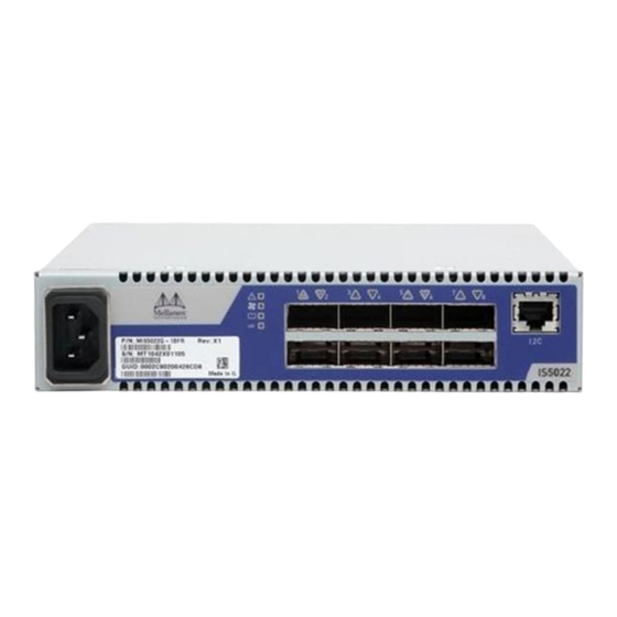
The Serial number and GUID for the switch are found on the front panel below the Mellanox logo. The serial number and product version information are found on the label seen in the figure below. Figure 1: Generic Product label Also on this label is the GUID identifier for the switch. Mellanox Technologies... -
Page 11: Chapter 2 Installation Safety Warnings
The chassis should not be stacked on any other equipment. If the chassis falls, it can cause bodily injury and equipment damage. 5. During Lightning - Electrical Hazard During periods of lightning activity, do not work on the equipment or connect or disconnect cables. Mellanox Technologies... - Page 12 For European connection, select a power supply cord that is internationally harmonized and marked “<HAR>”, 3 - conductor, minimum 1.0 mm 2 wire, rated at 300 V, with a PVC insulated jacket. The cord must have a molded plug rated at 250 V, 10 A. Mellanox Technologies...
- Page 13 According to the WEEE Directive 2002/96/EC, all waste electrical and elec- tronic equipment (EEE) should be collected separately and not disposed of with regular household waste. Dispose of this product and all of its parts in a responsible and environmentally friendly way. Mellanox Technologies...
-
Page 14: Chapter 3 Externally Managed Switches
Externally managed switches must be managed by management software installed on a node or on another managed switch that can be anywhere in the fabric. This can be OpenSM, Mellanox FabricIT™ EFM, Mellanox UFM™, or a third party Subnet Manager. Mellanox Technologies... -
Page 15: Chapter 4 Hardware Basic Operation And Installation
When the switch is plugged in, within three seconds: • the Status LED should light up green. • The Fan LED should light up green. • The Bad Port LED should be off. • The Unit ID LED should be off. Mellanox Technologies... -
Page 16: Figure 3: Status Leds
Table 3 - Switch Status LED Configurations LED Description No power to the switch Switch is running Solid Green All OK There is a problem with power output from the power supply, or there is a thermal shut down. Mellanox Technologies... -
Page 17: Table 4: Fan Led Configurations
This LED shows symbol errors. Possible causes for this are: • bad cable • bad connection • bad connector This LED lights up when one or more ports is receiving a symbol error. The LED immediately goes off until the next symbol error is received. Mellanox Technologies... -
Page 18: Air Flow
4.1.1.5 UID LED Switch Identifier The UID LED is a debug feature that will become available to customers in the near future. For details please contact Mellanox Technologies support. 4.1.1.6 Port Connector LED Above the ports are two LEDs one for the upper port and one for the lower port . -
Page 19: Interfaces
There is one interface to connect to the switch. It is an I2C RJ45 interface labelled “I2C”. Use this connector to update firmware (as a last resort) and for advanced debug. Update FW inband only. 4.5.1 RJ-45 Connector (I2C) There is an “I2C”interface on the front panel. Mellanox Technologies... -
Page 20: Figure 6: Rj45 I2C Connector
FW tools cannot successfully reburn the correct image. Warning: Any red status LED is cause for concern and must be dealt with imme- diately. It can take up to 30 seconds to boot up, during which time the status LED may indicate red. Mellanox Technologies... -
Page 21: Chapter 5 Installation
8cm (3”) of space to the front and rear of the switch. This will ensure proper air flow through the chassis. This is crucial for maintaining good air- flow at ambient temperature. In particular, route cables such that they do not impede the air into or out of the chassis. Mellanox Technologies... -
Page 22: Installing The Switch In The Rack
Peel and stick the four rubber bumpers into the bottom of the switch. Place them in the round circles. Figure 7: Placing the Bumpers Bottom of the switch Place on a flat surface. Make sure the switch is sits solid on the surface. Connect the power cord. Mellanox Technologies... -
Page 23: Installation Procedure For A Single Switch Center-Of-Rack Installation
ESD strap is touching your skin and that the other end is connected to a verified ground. Screw the two front brackets to the front side of the switch using 4 flat head screws for each bracket. Figure 8: Installation Kit for a Single Centered Installation Mellanox Technologies... -
Page 24: Installation Procedure For A Side By Side Installation
• 4 switch mounted rails • 8 pairs of caged nuts and bolts • 24 flat head screws • 1 blank cover The Installation kits come with enough switch mounted rails and flat head screws to install two switches. Mellanox Technologies... -
Page 25: Figure 10: Installation Kit Parts For A Side By Side Installation
ESD strap is touching your skin and that the other end is connected to a verified ground. Screw the two switch mounted rails to the switch using six flat head screws per rail. Figure 11: Screw on the Switch Mounted Rails Mellanox Technologies... -
Page 26: Figure 12: Caged Nut Placement
Install the blank into the frame opposite the switch, or install a second switch. The front panel is not symetrical. The large radius always goes ot the center of the frame. Figure 13: Front Panel Orientation Large radius Small radius Small radius Mellanox Technologies... -
Page 27: Grounding The Switch
QSFP port will light when the physical connection is established (that is, when the unit is powered on and a cable is plugged into the port with the other end of the connector plugged into a functioning port). After plugging in a cable, lock the connector using the latching Mellanox Technologies... -
Page 28: Disassembly Of The Switch From The Rack
Loosen the two thumbscrews holding the switch in place. Slide the switch out of the rack. This switch needs to be supported when it is being disassembled. Remove the rails. Remove the caged nuts. Mellanox Technologies... -
Page 29: Disassembly Procedure - Side By Side Installation
=> Support > Download Center and go to the InfiniS- cale IV Switch systems. Click in the Table for the firmware image that you need. 5.5.1 Current Firmware Revision The user can query for the currently loaded firmware revision by using the command: ibstat Mellanox Technologies... - Page 30 Query the switch to determine the current FW version: [root@mymach]> flint -d /dev/mst/SW_MT48438_lid-0x0003 q Image type: FW Version: 7.3.0 Device ID: 48438 Chip Revision: Description: Node Sys image GUIDs: 0002c902004177d8 0002c902004177db Board ID: n/a (MT_0D00110012) VSD: PSID: MT_0D00110012 Mellanox Technologies...
-
Page 31: Figure 15: Mtusb-1 With Cables
RJ45 male. Use the cable that matches your switch. The other is a USB cable with one type A host connection to be connected to the server or PC and a type B connection to be connected to the MTUSB adapter. Figure 16: I2C Cable Connected to IS5022 IS5022 Mellanox Technologies... -
Page 32: How To Get Mellanox Firmware Tools (Mft)
To manage the Mellanox switch system using OFED, download Mellanox Open Fabrics from http://www.mellanox.com > Support > InfiniBand Software and Drivers. Be sure to read and follow all of the instructions regarding the installation and use of these tools. Mellanox Technologies... -
Page 33: Chapter 6 Troubleshooting
Check that the connections are good(no cable weight on the connector, no twists in the cable at the connector...). Check the port connectors at both ends. The switch is off: Unplug the switch. Wait 5 minutes. Plug in the switch. Mellanox Technologies... - Page 34 Unplug the switch. Wait 5 minutes. Plug in the switch. If the switch does not come on, check the power supplies. If the switch comes on, use the management software to determine the cause of the shut- down. Mellanox Technologies...
-
Page 35: Appendix A Specification
Max: 8 port QDR Optical Cable Passive Cables Max Length: Active Cables Port Types: QSFP QSFP Max Power per port for active cables: 2.0W Temperature: 0 to 45 Celsius Humidity: 10% - 90% non-condensing Protocol Support Regulatory Compliance Mellanox Technologies... -
Page 36: Emc Certification Statements
EMC Certification Statements Table 9 lists the approved certification status per switch in different regions of the world. Table 9 - Switch Certification Status ICES VCCI Switch P/N Class Class Class cTUVus (Japan) (USA) (Europe) (Canada) IS5022Q-1BRR IS5022Q-1BFR Mellanox Technologies... - Page 37 § 15.21 Statement Warning! Changes or modifications to this equipment not expressly approved by the party responsible for compliance (Mellanox Technologies) could void the user's authority to operate the equipment. §15.105(a) Statement NOTE: This equipment has been tested and found to comply with the limits for a Class A digital device, pursuant to Part 15 of the FCC Rules.
- Page 38 Statement § 15.21 Statement Warning! Changes or modifications to this equipment not expressly approved by the party responsible for compliance (Mellanox Technologies) could void the user's authority to operate the equipment. §15.105 Statement NOTE: This equipment has been tested and found to comply with the limits for a Class B dig- ital device, pursuant to part 15 of the FCC Rules.
-
Page 39: Vcci Statements (Japan)
Class A Device This device is registered for EMC requirements for industrial use. The seller or buyer should be aware of this. If this type was sold or purchased by mistake, it should be replaced with a residential-use type. Mellanox Technologies... -
Page 40: Appendix B Qsfp Interface
+3.3 V Power supply transmitter Vcc 1 +3.3 V Power Supply LPMode Low Power Mode Ground Tx3p Transmitter Non-Inverted Data Input Tx3n Transmitter Inverted Data Input Ground Tx1p Transmitter Non-Inverted Data Input Tx1n Transmitter Inverted Data Input Ground Mellanox Technologies... -
Page 41: Figure 17: Qsfp Male And Female Connections
QDR InfiniBand Switch Platform User Manual Rev 1.2 Figure 17: QSFP Male and Female Connections 18.35 View into Rear of Connector 8.50 18.35 View into Front of Cage 8.50 Mellanox Technologies... -
Page 42: Appendix C Rj45 I2C Interface
Rev 1.2 Appendix C: RJ45 I2C Interface The RJ45 I2C interface uses the EIA 568A standard wiring color coding. Looking into the Socket TXD+ Pin 1 TXD- RJ45_SDA RXD+ RXD- RJ45_SCL Pin 8 Looking into the Socket Mellanox Technologies... -
Page 43: Table 11: Replacement Parts Ordering Numbers
Power cord Type G for UK ACC000208 Power cord Type D for India ACC000209 Power cord Type I for China ACC000210 Power cord Type J for Switzerland ACC000211 Power cord Type B for Japan, ACC000212 Power cord Type I for Australia ACC000213 Mellanox Technologies... - Page 44 En général, il faut remplir la baie avec du matériel de bas en haut. 7. Installation du matériel Ce matériel ne doit être installé, remplacé ou entretenu que par du personnel formé et qualifié. Mellanox Technologies...
-
Page 45: Qdr Infiniband Switch Platform User Manual Rev
à 3 conducteurs, d’un diamètre de fil minimum de 0,75 mm2, d’une tension nominale de 300 V, avec une gaine isolée en PVC. Le cordon doit avoir une fiche moulée d’une tension nominale de 250 V et d’une intensité nominale de 10 A. Mellanox Technologies... -
Page 46: Appendix F Installation - Sicherheitshinweise (German)
Vorsichtsmaßnahmen zu ergreifen, um die Stabilität des Systems zu gewährleisten. Im Allgemeinen sollten Sie das Gestell von unten nach oben mit Geräten füllen. 7. Geräteinstallation Diese Gerät sollte nur von geschultem und qualifiziertem Personal installiert, ausgetauscht oder gewartet werden. Mellanox Technologies... - Page 47 QDR InfiniBand Switch Platform User Manual Rev 1.2 8. Geräteentsorgung Die Entsorgung dieses Geräts sollte unter Beachtung aller nationalen Gesetze Bestimmungen erfolgen. 9. Regionale und nationale elektrische Bestimmungen Dieses Gerät sollte unter Beachtung der regionalen und nationalen elektrischen Bestimmungen installiert werden. Mellanox Technologies...
- Page 48 En general, en un bastidor, los equipos se deben insta- lar comenzando desde abajo hacia arriba. 7. Instalación de equipos La instalación, el reemplazo y el mantenimiento de este equipo estarán a cargo únicamente de personal capacitado y competente. Mellanox Technologies...
- Page 49 CIÓN, del terminal de puesta a tierra de protección separado al conductor de tierra de protección del edificio. El equipo se instalará en un área donde haya conexión equipotencial, como por ejemplo, un centro de telecomunicaciones o una sala de computadoras dedicada. Mellanox Technologies...
- Page 50 (EEE) se deben recolectar por separado y no se deben eliminar junto con residuos domésticos. Al deshacerse de este producto y de todas sus partes, hágalo de una manera res- ponsable y respetuosa con el medio ambiente. Mellanox Technologies...
- Page 51 Do not connect this unit to any outlet that is not fully grounded! • Finland “Laite on liitettävä suojamaadoituskoskettimilla varustettuun pistora- siaan” • Norway “Apparatet må tilkoples jordet stikkontakt” Unit is intended for connection to IT power systems for Norway only. • Sweden “Apparaten skall anslutas till jordat uttag.” Mellanox Technologies...
Need help?
Do you have a question about the MIS5022Q-1BRR and is the answer not in the manual?
Questions and answers