Table of Contents
Advertisement
Quick Links
Advertisement
Table of Contents

Related Manuals for Mellanox Technologies Grid Director 4700


Summary of Contents for Mellanox Technologies Grid Director 4700
- Page 1 Mellanox Grid Director 4700 Installation Manual www.mellanox.com...
- Page 2 Names and logos identifying products of Mellanox in this document are registered trademarks or trademarks of Mellanox. Voltaire is a registered trademark of Mellanox Technologies, Ltd. All other trademarks mentioned in this document are the property of their respective owners.
-
Page 3: Table Of Contents
Contents Contents Preface ..............................8 Introduction ........................... 10 Mellanox Grid Director™ 4700 Overview ................10 Main Features ........................13 Product Architecture ......................14 1.3.1 Main Building Blocks ....................14 1.3.2 Reset Buttons ......................16 Management ......................... 17 System Configurations ......................... 18 Configuration Summary ...................... - Page 4 3.29 Statement of Volatility ......................41 Packing and Unpacking ....................... 42 Package Contents ........................ 42 Unpacking the Grid Director 4700 ..................44 Packing the Grid Director 4700 Switch ................. 45 Preparing for Installation ......................47 Tools Required for Installation ....................47 Site Planning ......................... 47 Rack Requirements ......................
- Page 5 Contents Mounting Process Summary ....................54 Assembling and Mounting the Rails ..................54 6.2.1 Rail Kit and Mounting Components ................ 55 6.2.2 Rail Kit Assembly Overview ..................55 6.2.3 Rail Kit Assembly Procedure .................. 57 Mounting the 4700 in a Rack (Standard Installation) ............60 Mounting the HyperScale Chassis in a Rack ...............
- Page 6 1GbE Ports (Management) ....................88 List of Figures Figure 1: Grid Director 4700 with Standard Fabric Boards – Front ............11 Figure 2: Grid Director 4700 with HyperScale Fabric Boards – Front ........... 11 Figure 3: Grid Director 4700 – Rear ...................... 12 Figure 4: 4700 Block Diagram .......................
- Page 7 Contents Figure 36: Cable Management for Switches with HyperScale Fabric Boards ........81 Figure 37: Cabling Dressing between Switches Installed Back-to-Back ..........83 Figure 38: QSFP Connector-Dimensions ....................86 Figure 39: Straight-through Cables ....................... 88 Figure 40: Cross-connect Cables ......................88 List of Tables Table 1: Module Configuration per Chassis ..................
-
Page 8: Preface
Audience The manual is intended primarily for system administrators who are authorized to install a Grid Director 4700 switch. It is assumed that the readers are familiar with the InfiniBand technology and terminology. Related Documentation For additional information, refer to the following documents: ... - Page 9 Contents CAUTION: Alerts you to the risk of personal injury, system damage, or loss of data. WARNING: Warns you that failure to take or avoid a specific action might result in personal injury or a malfunction of the hardware or software. Be aware of the hazards involved with electrical circuitry and be familiar with standard practices for preventing accidents before you work on any equipment.
-
Page 10: Introduction
Introduction Introduction This chapter provides a description of the Mellanox Grid Director 4700 chassis and its system boards. Mellanox Grid Director™ 4700 Overview Mellanox’s fourth-generation Grid Director™ 4000 series of smart switches addresses the growing size and complexity of clusters by providing high interconnect bandwidth, advanced carrier-class management and a unique HyperScale™... -
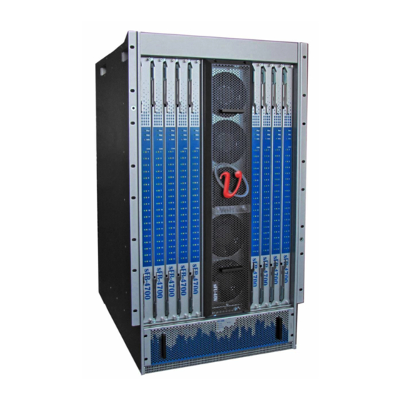
Page 11: Figure 1: Grid Director 4700 With Standard Fabric Boards - Front
Mellanox Grid Director 4700 Installation Manual Figure 1: Grid Director 4700 with Standard Fabric Boards – Front Figure 2: Grid Director 4700 with HyperScale Fabric Boards – Front... -
Page 12: Figure 3: Grid Director 4700 - Rear
Introduction Figure 3: Grid Director 4700 – Rear... -
Page 13: Main Features
Mellanox Grid Director 4700 Installation Manual Main Features Ultra-low latency: between 100 and 300 nanoseconds port-to-port 324 QDR (40Gb/s) auto-negotiating QSFP InfiniBand ports in a 19U switch 648 port option can be divided between two racks for weight distribution and greater ease of cabling ... -
Page 14: Product Architecture
Cabling for InfiniBand, management, and power located at rear of chassis Local and remote management and provisioning using CLI (Command Line Interface). 1.3.1 Main Building Blocks The Grid Director 4700 rear panel has 18 slots in which you can install the Line Boards (sLB-4018). -
Page 15: Figure 4: 4700 Block Diagram
Midplane.) The Midplane is not field serviceable. Line Boards The rear side of the Grid Director 4700 can host up to up to eighteen 18-Port QDR (40Gbps) Line Boards (sLB-4018). Each line board has 18 external QSFP interfaces, and 18 internal 4X InfiniBand interfaces for connectivity between the Line cards and the Switch fabric. -
Page 16: Reset Buttons
Management Board front panel. Management Reset To reset the Grid Director 4700, push any of the reset buttons using a thick wire or tip of a pen. Pressing the Reset button for one second resets the sMB-CM Management Board only;... -
Page 17: Management
Mellanox Grid Director 4700 Installation Manual Management The Grid Director 4700 includes smart device management that provides a simple interface for deploying, troubleshooting, maintaining and upgrading the switch. With a simple to use CLI interface, routine tasks such as monitoring the switch operation or upgrading software and firmware are made simple. -
Page 18: System Configurations
System Configurations System Configurations Configuration Summary This section summarizes the configuration for the Grid Director 4700 modules. 2.1.1 Module Configuration per Chassis The following table provides a comprehensive list of modules per chassis, as well as the maximum number of modules that can be installed in a 4700 system. -
Page 19: Specifications Summary
1 HyperScale cabling guide bracket 2x bracket long 8 screws 2.1.2 Specifications Summary The following table summarizes the Grid Director 4700 specifications. Table 2: Feature Summary Table Feature 4700 Rack Height HyperScale Rack Height Rack Width 19"... -
Page 20: Switch Internal Topology
The Grid Director 4700 features an internal Clos network with Line Boards as the edge (leaf) switches and Fabric Boards as the core (spine) switches. Each Line Board switch chip is connected to each switch chip on the Fabric Boards through one or more InfiniBand connections. -
Page 21: Switching Topologies
There are fewer cables to wire Ultimate application performance (large non-blocking islands and minimize application specific tuning/layout). 2.3.2 Switching Topologies The following figure illustrates the Grid Director 4700 InfiniBand internal switching topology. Figure 5: Grid Director 4700 Switching Topology... -
Page 22: Figure 6: Grid Director 4700 Hyperscale Spine Switching Topology
System Configurations The following figure illustrates the Grid Director 4700 with HyperScale Fabric Board (spine) InfiniBand internal switching topology. Figure 6: Grid Director 4700 HyperScale Spine Switching Topology The Grid Director 4700 topology feature eighteen symmetrical Line Boards (sLB) and nine interconnect Fabric Boards (sFB). -
Page 23: Hyperscale™ Configurations
Mellanox Grid Director 4700 Installation Manual HyperScale™ Configurations 2.3.3 HyperScale – Mesh Configuration Figure 7: HyperScale – Mesh Configuration Multiple 4700 chassis can be connected in a mesh This configuration uses 4700 stacking fabric boards and 4700 switches ... -
Page 24: 4700 Specifications
4700 Specifications 4700 Specifications 4700 Architecture 9 slots of Fabric boards in front of the chassis 18 slots for Line Boards Based on passive Midplane board which allow the IB differential signals, control signals and power connectivity between the different boards in the chassis ... -
Page 25: 4700 Management Board (Smb-Cm) Specifications
Mellanox Grid Director 4700 Installation Manual Port-to-port Latency - Under 100 nanoseconds Data Virtual Lanes - 8 Management Virtual Lanes - 1 MTU - 4096 Bytes, max Maximum hops - 1 hop between ports on the same board. 3 hops between different Line Boards in the same chassis. -
Page 26: Torque Settings
4700 Specifications Figure 10: 4700 Line Board Slot Numbering For specific instructions, refer to System Cabling (on page 77). Torque Settings Table 5: Torque Settings for Module Assembly Assembly Torque (in/lb) sLB-4018 Line Board to chassis 2 (or use manual screwdriver) sMB Management Board to chassis 2 (or use manual screwdriver) Rail kit part A to part B... -
Page 27: Module Configuration Rules
Management Board is installed. For more information, refer to Installing the Management Board (sMB-CM). The Grid Director 4700 supports any Fabric Board configuration (between 1 and 9). When installing the line boards, start at the bottom of the chassis. For more information, refer to Installing the Line Board (sLB-4018. -
Page 28: Power Characteristics
4700 Specifications Indicators Operational AC and DC Status LEDs Operating voltage 100–240 VAC, 50–60 Hz auto-sensing Power factor 0.98 typical at 230Vac, full load 0.98 typical at 115Vac, full load Temperature rating 0–45 degrees Centigrade 3.9.3 Power Characteristics Table 8: Power Characteristics Attribute Specification Comments... -
Page 29: Calculating Heat Output In Btus
Mellanox Grid Director 4700 Installation Manual This formula provides margin for momentary power peaks and enhances reliability by preventing the power subsystem from continuously operating at maximum power. 3. For redundancy (N:1 or N:N), configure additional power supplies. Table 10: Module Power Data Mellanox Grid Director™... -
Page 30: Maximum Heat Dissipation
4700 Specifications Configuration Modules Included Power (Watts) Heat Output (BTUs) 324 ports QSFP copper 9 sFB-4700, 18 sLB-4018, 1 sFU-40H, 1 4,244W 14,479 sFU-40V, 2 sMB, 3 sPSU-S 324 ports QSFP copper + 9 sFB-4700x2, 18 sLB-4018, 1 sFU-40H, 1 5,279W 18,010 HyperScale Fabric Boards... -
Page 31: Led Indicators
4700 with HyperScale Fabric Boards 41.5 12.5 12.2 16.34 29.5 4.92 27.12 (1) 1 in = 2.54 cm (2) 1 kg = 2.205 lbs 3.15 LED Indicators This section specifies the LED indicators of the different Grid Director 4700 modules. -
Page 32: Slb-4018 Line Board Leds
4700 Specifications 3.15.1 sLB-4018 Line Board LEDs Table 17: sLB-4018 Line Board LEDs Indication LED Description Remarks Link State The two LEDs in each pair are as follows: Indicates the state of the QSFP connectivity. Green – ON indicates physical link up 18 Amber LEDs ... -
Page 33: Hyperscale Fabric Board (Sfb-4700-2X) Leds
Mellanox Grid Director 4700 Installation Manual Indication LED Description Remarks OFF – No attention required User only Blinking – Chassis attention required OFF – Card not Ready Card Ready (Green) ON – Card ready Blinking Slowly – Card loading Blinking Fast – Card problem 3.15.3... -
Page 34: Sfu-40H Horizontal Fan Unit Leds
4700 Specifications Indication LED Description Remarks ON – Vertical and Horizontal fan unit fault indication. Indicates that at least one of the 13 fans has failed. OFF – Indicates normal temperature levels. Temp (Orange) Temp (Orange) ON – Indicates an over-temperature fault on the chassis. FM Active (Green) OFF - Fabric Manager is not active ON - Fabric Manager running on the Management... -
Page 35: Spsu-S Power Supply Leds
Mellanox Grid Director 4700 Installation Manual 3.15.6 sPSU-S Power Supply LEDs Table 22: sPSU-S Power Supply LEDs Indication Description ON – Indicates that the DC power source is present. DC ON (Green) ON – Indicates that the AC power source is present. -
Page 36: Certifications
4700 Specifications Table 25: MTBF per Module Data Chassis/Module Description MTBF (Hours) sFB-4700 9 QDR port connections fabric board 519, 426 sFB-4700-2X 9 QDR port connections x2 fabric board 345,941 sLB-4018 sLB-4018, 18 QSFP ports per sLB-4018 419,866 sMB-CM Management Management board 441,273 Board... -
Page 37: Declarations
Mellanox Grid Director 4700 Installation Manual EN 61000-3-3:95+A1 (01) Voltage fluctuations and flicker Japan VCCI Technical Requirements, V.3/2001.04/CISPR 22:1997 + A1: 2000 + A2: 2002, Class A. Australian/New Zealand C-Tick, AS/NZS CISPR 22:04 KCC Korea Restricted Hazardous Substances Certification... -
Page 38: Label(S)
4700 Specifications 3.21 Label(s) The Grid Director 4700 label (example) below shows safety and EMC text and logos. Figure 11: 4700 Label (example) 3.22 Gost-R Certification Mellanox products comply with the Gost-R Russian safety regulations. 3.23 KCC-Korea Certification Mellanox products comply with the Korean KCC regulations. -
Page 39: Shock And Vibration Test Reports
3.25 Shock and Vibration Test Reports Prepare the Grid Director 4700 to ship in a rack by carefully following the rail kit installation instructions, as detailed in Assembling and Mounting the Rails. The Grid Director 4700 is susceptible to shock and vibration if the rail kit installation instructions are not followed precisely. -
Page 40: Export Information
4700 Specifications Table 28: Free Fall Test Description Drop Height 0.1 meter Number of drops of test One drop performed on the bottom face, 2 edges and 2 corners of the test item item Total number of drops 5 drops 3.26 Export Information Composite Theoretical Performance (CTP) is a calculation measured in MTOPS (millions of... -
Page 41: Center Of Gravity Data
Mellanox Grid Director 4700 Installation Manual 3.28 Center of Gravity Data This section provides the Grid Director 4700 center of gravity specifications. The measurement origin starts at the front lower left corner of the chassis. Figure 12: Center of Gravity Data Center of gravity for minimum, typical, and maximum configurations are shown in the following table. -
Page 42: Packing And Unpacking
Two power supply units (sPSU-S). The Grid Director 4700 chassis is shipped with a horizontal fan unit (sFU-40H) and a vertical fan unit (sFU-40V) installed at the front of the chassis and two power supplies at the rear of the chassis. - Page 43 Mellanox Grid Director 4700 Installation Manual Part Number Description Grid Director 4700 Top Foam Cable Management Mounting Rails (Left and Right) Foam Plate Carton Plate – placed at the top of the rear of the chassis to protect the opening...
-
Page 44: Unpacking The Grid Director 4700
2. Remove the box from around the chassis by sliding it upwards, as shown. The Grid Director 4700 chassis in its partially unpacked state is shown as follows. The upper packing foam covering the Grid Director 4700 contains the following components: ... -
Page 45: Packing The Grid Director 4700 Switch
3. Remove all of the accessories listed above and as well as the packing foam on top of the chassis. 4. Lift the Grid Director 4700 from the pallet and place it on a flat surface. Due to the weight of the Grid Director 4700 chassis, two people are required to perform this. -
Page 46: Figure 13: 4700 Switch Packed
Packing and Unpacking Figure 13: 4700 Switch Packed Chapter 5... -
Page 47: Preparing For Installation
This chapter describes how to prepare your site. Read this chapter before you install the switch. Tools Required for Installation The following tools and materials are required for mounting the Grid Director 4700 chassis. Table 31: Required Tools and Materials Quantity... -
Page 48: Rack Requirements
The HyperScale cable guide requires an additional 1U of rack space, making the total height 20U instead of 19U. Clearance Requirements You should be certain to provide sufficient clearance around the racks to install and maintain the Grid Director 4700. Clearance specifications are detailed in Chapter 3 (on page 27). Site Environment Specifications The system can continue to operate within specified environmental ranges;... -
Page 49: Figure 14: 4700 Grounding Connection
Mellanox Grid Director 4700 Installation Manual The Grid Director 4700 is delivered with a grounding stud kit. The system must be permanently grounded using the grounding stud. The grounding kit includes the following items: A 10-32 5/8" screw ... -
Page 50: Figure 16: Grounding Holes For 4700
The Grid Director 4700 provides two grounding options, as shown. For convenience, grounding can be performed from any of these locations. Figure 16: Grounding Holes for 4700 Install the grounding stud before you mount the Grid Director 4700 chassis onto the rack. - Page 51 Mellanox Grid Director 4700 Installation Manual To install the Grounding Stud: 1. Insert a 10-32 5/8" screw through the Grounding hole, rear-to-front, as shown. 2. Add a spring washer onto the 10-32 5/8" thread, this time front-to rear. 3. Add a nut #10.
-
Page 52: Power Requirements
16A for Europe or 20A for North America. The amount of required power supplies per system is set according to system configuration. When the Grid Director 4700 is fully configured, it supports N:1 redundancy, as shown in the example below. -
Page 53: Figure 17: 4700 Fully Configured - N:1 Redundancy
Mellanox Grid Director 4700 Installation Manual Figure 17: 4700 Fully Configured - N:1 Redundancy The following table describes the Grid Director 4700 N:1, N:N, and N:M redundancies. Table 32: 4700 QDR N:1/N:N Redundancy Configuration Modules Included Non-redundant N:N or N:M... -
Page 54: Rack-Mounting The 4700 Chassis
Rack-Mounting the 4700 Chassis Rack-Mounting the 4700 Chassis Mounting Process Summary The 4700 chassis is mounted in a standard 19" rack with the Fabric Boards facing the front of the rack. The 4700 is provided with an adjustable rail kit to accommodate racks of differing depth. -
Page 55: Rail Kit And Mounting Components
Mellanox Grid Director 4700 Installation Manual 6.2.1 Rail Kit and Mounting Components The 4700 package includes: Rail kit Mounting ears (or 19" brackets) that are factory installed at the front of the chassis The supplied rail kit is adjustable to allow for mounting the chassis in racks of varying depths. -
Page 56: Figure 18: Overview Of Assembled Rail Kit
Rack-Mounting the 4700 Chassis The following image shows the two rails completely assembled and displays the left rack assembled to the rack, and how the left rail looks when it is attached to the rack. Figure 18: Overview of Assembled Rail Kit ... -
Page 57: Rail Kit Assembly Procedure
Mellanox Grid Director 4700 Installation Manual 7. Attach the front side of the rail to the rack’s front vertical side rail with 2 screws for each side and the rear side of the rail to the rack’s rear vertical side rail with 2 screws for each side. -
Page 58: Figure 19: Positioning The Insert In Front Of The Right Bracket
Rack-Mounting the 4700 Chassis The rail supports six or eight 8-32 5/8" screws. Eight is recommended. Figure 19: Positioning the Insert in Front of the Right Bracket Figure 20: Assembling the Rail Bracket 2. Select the round holes in the bracket. 3. -
Page 59: Figure 22: U Alignment
Mellanox Grid Director 4700 Installation Manual 2. Align the rail mounting holes with the mounting holes in the equipment rack as displayed previously. 1. Position the rail brackets in alignment with the 1U mark on the Rack. Note: you can install any equipment adjacent to the rail kit as long as you align the rail kit with the "U"... -
Page 60: Mounting The 4700 In A Rack (Standard Installation)
Rack-Mounting the 4700 Chassis 3. Go back and tighten the screws that were used to connect the two parts of the rail in Step 1. IMPORTANT: If you do not tighten the screws, the chassis cannot be mounted safely in the rack. - Page 61 Mellanox Grid Director 4700 Installation Manual 4. Secure the chassis through the holes in the Front Rack rail using 16 screws (8 for each side) and adequate clip nuts, as shown. 5. To stabilize the chassis for transport, secure the 4700 chassis onto the rail by using three 8-32 screws, 3/8"...
-
Page 62: Mounting The Hyperscale Chassis In A Rack
Rack-Mounting the 4700 Chassis Once the rack is installed on the premises, these screws should be taken away so that you can remove the chassis in case the sides of the rack are not accessible. Figure 23: Securing the 4700 Chassis for Transport - Regular Configuration Figure 24: Securing the 4700 Chassis for Transport - HyperScale Configuration Mounting the HyperScale Chassis in a Rack The installation kit includes:... -
Page 63: Figure 25: Installing The 19-In Long Bracket
Mellanox Grid Director 4700 Installation Manual To mount the HyperScale 4700 chassis into the rack: 1. Install the rail kit, as described in Assembling and Mounting the Rails (on page 54). 2. Swap the standard 19-in rack mount bracket with the 19-in long bracket (provided in the... -
Page 64: 4700 Power-Up
Rack-Mounting the 4700 Chassis 4700 Power-Up Once the 4700 chassis is secure within the rack, electrical cables from the power distribution source can be fitted in preparation for connection. Power cords are supplied by Mellanox according to the system configuration, one per power supply unit. -
Page 65: Installing System Boards
Every slot that is not populated with a module must be covered with a blank panel for proper cooling. 7.1.1 4700 Chassis The front panel of a Grid Director 4700 includes: Nine slots for Fabric Boards (sFB) sFU-40H horizontal fan unit ... -
Page 66: Figure 26: Using Ejectors To Install A Line Board
Installing System Boards Line Board Press the ejector inward on both ends of the Line Board. Figure 26: Using Ejectors to Install a Line Board Pull the ejector outward on both ends of the Line Board. Figure 27: Using Ejectors to remove a Line Board It is recommended to insert boards from top to bottom, starting from slot 1 down to 18. -
Page 67: Installing Fabric Boards
Mellanox Grid Director 4700 Installation Manual Pull the ejector outward on both ends of the Line Board. Figure 29: Using Ejectors to remove a Fabric Board The ejector mechanism on the Management Board (sMB-CM) is the identical to the one used on the Line and Fabric boards. - Page 68 Installing System Boards Refer to LED Indicators (on page 31) for a comprehensive list of LEDs, LED description, and functionality. To insert a Fabric Board into the chassis: 1. Verify that the ejectors are fully opened. 2. Carefully seat the board into the side guide rails. ...
-
Page 69: Installing The Line Board (Slb-4018 )
Mellanox Grid Director 4700 Installation Manual 3. Gently press the ejectors inward. 4. Tighten the two security screws. 5. Verify the following LED conditions: Power LED: ON Info LED: OFF Rdy LED: Starts to blink slowly ... -
Page 70: Installing The Management Board (Smb-Cm)
Installing System Boards Installing the Management Board (sMB-CM) You can either install one or two sMB-CMs in the back of the 4700 chassis. Figure 31: Front Panel of the Management Board The Management Board provides one RS-232 port and one Ethernet port for management capabilities. -
Page 71: Figure 32: Front Panel Of The Power Supply Module
Mellanox Grid Director 4700 Installation Manual Refer to the Regulatory Compliance and Safety Reference Manual before connecting the power supplies to mains. Figure 32: Front Panel of the Power Supply Module To insert a power supply unit into the chassis: 1. -
Page 72: Fan Units (Sfus)
Installing System Boards This mark applies only to countries within the European Union (EU) This label is applied to various batteries to indicate that the battery is not to be thrown away, but rather reclaimed upon end of life per this Directive. In accordance with the European Directive 2006/66/EC, batteries and accumulators are labeled to indicate that they are to be collected separately and recycled at end of life. -
Page 73: Vertical Fan Unit (Sfu-40V)
Mellanox Grid Director 4700 Installation Manual 7.7.1 Vertical Fan Unit (sFU-40V) The sFU-40V vertical fan unit, shown in the following figure, is part of the 4700 air cooling system; it provides cooling of the Line Boards and the management boards. It includes 5 fans with fan speed control;... -
Page 74: Horizontal Fan Unit (Sfu-40H)
Installing System Boards 3. Within five minutes, replace with a new sFU-40V and place and tighten the four screws. 4. Listen for proper sFU-40V fan operation. 7.7.2 Horizontal Fan Unit (sFU-40H) The sFU-40H horizontal fan unit, shown in the following figure is part of the 4700 air cooling system;... -
Page 75: Verifying Installation
Mellanox Grid Director 4700 Installation Manual Verifying Installation Verifying installation of the 4700 consists of making sure that it starts up properly and that the network connections are operational. Verifying Start-up Operations To verify that the 4700 starts up properly: 1. -
Page 76: Identifying Startup Problems
Verifying Installation Chassis fan units which operate when the system power is connected. The fan units will not continue to operate when power is disconnected Management Board (CLI/Eth) Line Board (sLB-4018) Fabric Boards (sFB-4700/sFB-4700x2) The following are simple checks you can make to determine if there is a fan problem: ... -
Page 77: System Cabling
Mellanox Grid Director 4700 Installation Manual System Cabling Cabling Guide Brackets Installation on Either Sides of the Chassis (Line Boards Cables) The 4700 cabling guide brackets are installed at the rear of the rack, in-line with the Line Boards and are designed to accommodate adequate cable bend radius. -
Page 78: Installing Cabling Guide Brackets
System Cabling 9.1.1 Installing Cabling Guide Brackets Left and Right brackets are marked "L" for left and "R" for right. When installed, make sure that the grips face out. The rack-gripping brackets shown, are installed on the 4700 rack’s rear rail. ... -
Page 79: Infiniband Cabling On Either Side Of The Chassis (For Line Cables)
Mellanox Grid Director 4700 Installation Manual 9.1.2 InfiniBand Cabling on Either Side of the Chassis (for Line Cables) It is recommended to dress the cables connected to the InfiniBand connectors of each line board into two groups, left and right, and fasten them down gently after connectivity has been verified. -
Page 80: Cabling Guide Brackets Installation Under The Chassis (Fabric Board Cables)
System Cabling The following figure shows the 4700 cable dressing: Figure 34: 4700 Cable Dressing Cabling Guide Brackets Installation under the Chassis (Fabric Board Cables) HyperScale cabling guide bracket are installed at the front of the rack, between two preinstalled switches. The bracket is designed to accommodate adequate cable bend radius. The cabling guide bracket is part of a kit for setting up a 648-port configuration. -
Page 81: Installing Cabling Guide Brackets For Switches With Hyperscale Fabric Boards
Mellanox Grid Director 4700 Installation Manual 9.2.1 Installing Cabling Guide Brackets for Switches with HyperScale Fabric Boards The HyperScale chassis must be pre-installed in the rack with the 2 x 19" long bracket. The cabling guide bracket for HyperScale Fabric Boards is installed on the 4700 rack’s front rail, in a horizontal position, in parallel and between two HyperScale switches. - Page 82 System Cabling 3. Select a Fabric board in the bottom chassis and position the InfiniBand cable connector with the pulling tab at the right of the cable, and push the connector in place. 4. Verify that the cable is inserted properly into the connector by gently tugging the cable; verify that the Link State green-colored LED lights (and does not flash) indicating a good physical connection.
-
Page 83: Infiniband Cabling Guidelines
Mellanox Grid Director 4700 Installation Manual The following figure shows cabling between two 4700 installed back to back for a 648-port configuration: Figure 37: Cabling Dressing between Switches Installed Back-to-Back InfiniBand Cabling Guidelines It is recommended to dress the cables connected to the InfiniBand connectors of each sLB into two groups, left and right, and fasten them down gently after connectivity has been verified. -
Page 84: Infiniband Cabling-Do's And Don'ts
System Cabling InfiniBand Cabling—Do’s and Don’ts 9.3.1 Do not kink the cable. Do not over-bend the cable behind the connector. Do not twist the connector. If it is necessary to re-orient the connector, start the adjustment further down the cable, at least 75 cm away from the connector, so the twist occurs gradually along the cable instead of abruptly near the connector. - Page 85 Mellanox Grid Director 4700 Installation Manual management ports on the rear of the Chassis. Both types of management network can be connected simultaneously. To connect to the Management port Ethernet Interface: 1. Connect the end of the management cable with the single RJ-45 connector to the Management port on the 4700.
-
Page 86: Appendix A: Cabling Information And Specifications
System Cabling Appendix A: Cabling Information and Specifications This appendix provides supplemental information and specifications. QSFP Cable QSFP (Quad Small Form-factor Pluggable) Key Features: Small size, high density, hot-pluggable connector with four transmit and four receive channels Supports both types of cables: ... -
Page 87: Ib Port Cable Specifications
Mellanox Grid Director 4700 Installation Manual QSFP Cable Overview Every 4700 port on the switch is equipped with transmit and receive circuits that can adjust to fit different types of link characteristics and either optical or copper cables. The QSFP cables transmit and receive up to 10 Gbps per channel (total: up to 40 Gbps per port) over a single active/passive optical or copper cable, Passive copper cables do not consume any additional power while active copper and optic cables consume up to 2.5 Watt. -
Page 88: 1Gbe Ports (Management)
System Cabling Type Maximum Cable Length 98.4 CBL-00105 CBL-00106 328.1 CBL-00115 CBL-00212 984.2 CBL-00200 1GbE Ports (Management) Use modular, RJ-45, straight-through UTP cables to connect the 10/100/1000 Fast Ethernet ports to external switches/routers that relay management traffic. Use modular, RJ-45 cross-connect cables to connect to end systems. The following figures show straight-through cables and cross-connect cables.
Need help?
Do you have a question about the Grid Director 4700 and is the answer not in the manual?
Questions and answers