Table of Contents
Advertisement
Quick Links
Advertisement
Table of Contents

Related Manuals for Mellanox Technologies Grid Director 4036E


Summary of Contents for Mellanox Technologies Grid Director 4036E
- Page 1 Grid Director 4036E Installation Manual www.mellanox.com...
- Page 2 Names and logos identifying products of Mellanox in this document are registered trademarks or trademarks of Mellanox. Voltaire is a registered trademark of Mellanox Technologies, Ltd. All other trademarks mentioned in this document are the property of their respective owners.
-
Page 3: Table Of Contents
Rear Panel Description ......................17 Product Options ..........................19 Grid Director 4036E Available Configurations ..............19 InfiniBand Clusters Using the Grid Director 4036E .............. 19 Ordering Options ........................19 Technical Specifications and Certifications ................21 Grid Director 4036E Technical Specifications ..............21 Power Specifications - Power Supply Module .............. - Page 4 6.6.1 Rail Kit ........................32 6.6.2 Option 1 ........................34 6.6.3 Option 2 ........................40 Grid Director 4036E Power Up ..................... 44 Field Replaceable Units ......................44 6.8.1 Fan Unit ........................44 6.8.2 Power Supplies ....................... 45 Cabling ............................46 Cabling Overview........................
- Page 5 Table 3: Ordering Information for the Grid Director 4036E ..............19 Table 4: Ordering Information for the Grid Director 4036E Modules............. 19 Table 5: Grid Director 4036E List of Parts (According to Configuration) ..........20 Table 6: Grid Director 4036E Technical Data ..................21 Table 7: Power Supply Module Data .....................
- Page 6 Contents Table 9: 10GbE LED Indicators ......................25 Table 10: Vibration ..........................27 Table 11: Free Fall ..........................28 Table 12: Clearance Requirements ....................... 28 Table 13: Unpacked Weights & Dimensions ..................28 Table 14: Packed Weights & Dimensions ..................... 28 Table 15: Material and Tools Required ....................
-
Page 7: Preface
About this Manual This manual provides installation instructions for the high-bandwidth, low-latency scalable InfiniBand Mellanox Grid Director 4036E with 32 QDR and 2x10 GbE ports. It includes the product specifications, unpacking and installation information, unit power up, and initiation and troubleshooting procedures. - Page 8 Preface CAUTION: Alerts you to the risk of personal injury, system damage, or loss of data. WARNING: Warns you that failure to take or avoid a specific action might result in personal injury or a malfunction of the hardware or software. Be aware of the hazards involved with electrical circuitry and be familiar with standard practices for preventing accidents before you work on any equipment.
-
Page 9: Introduction
Introduction Grid Director 4036E Overview The Mellanox Grid Director 4036E is a high performance, low latency and fully non-blocking InfiniBand switch, which includes a built-in low latency Ethernet gateway for bridging traffic to and from Ethernet-based networks or storage. With thirty-four 40 Gbps InfiniBand ports (delivering 2.72 Tbps), less than 100 nanoseconds of port-to-port latency, and two 1/10Gb... -
Page 10: Management
Consolidates network and I/O infrastructure Plug & play, standards-based protocol bridging with zero configuration required on the Grid Director 4036E itself or on the servers Embedded subnet manager Transparent mapping between Ethernet VLANs and InfiniBand partitions to ensure continuity of security and service levels ... - Page 11 Grid Director 4036E Installation Manual The 4036E Gateway comes with an onboard subnet manager, enabling simple, out-of the-box fabric bring-up for small to medium clusters. Refer to the Grid Director 4000 Family User Manual for details on 4036E software requirements and configuration.
-
Page 12: Unpacking
Before unpacking, make sure that the box is sealed and undamaged. Before beginning the installation of the Grid Director 4036E, verify that the package contains all the items, as detailed in the Getting Started Guide. For alist of parts delivered... - Page 13 2. Remove the box containing the Rail Kit, the Power Cords, and the multipurpose console cable kit (Mng). 3. Remove the Getting Started Guide. 4. Remove the top foam. 5. Carefully remove the Grid Director 4036E. Use the dedicated niche to lift the switch, as shown in the following figure.
-
Page 14: Rail Kit (Kit-00008)
A RJ45 to DB-9 adaptor for RS-232 console connection. Figure 4: Console Cable Kit (Mng) Packing the Grid Director 4036E You may need to move the Grid Director 4036E to a different location or send it for repair; should this be necessary, pack the equipment as described below. - Page 15 Grid Director 4036E Installation Manual To pack the Grid Director 4036E, perform the following steps: 1. Unmount the Grid Director 4036E from the rack. 2. Disassemble the rail brackets and pack the parts in the rail kit box. 3. Insert the Grid Director 4036E into its antistatic bag.
-
Page 16: Getting Started
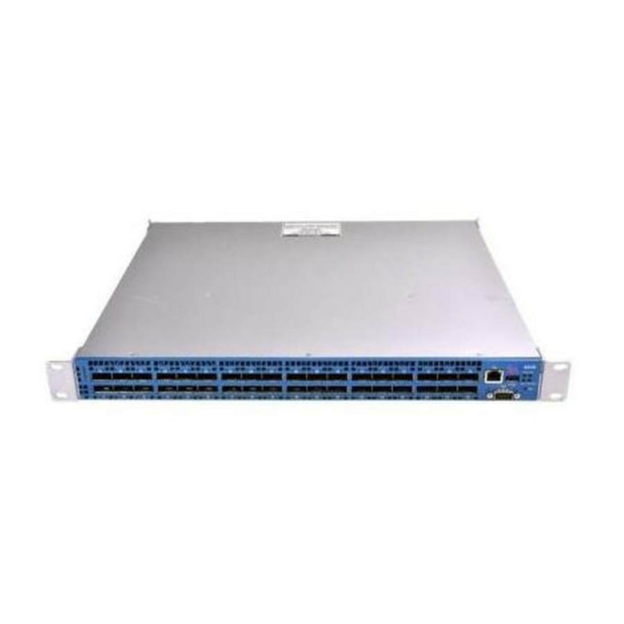
Grid Director 4036E. Front Panel Description This section details the front panel Grid Director 4036E. Figure 5: Grid Director 4036E Front Panel The following table details Grid Director 4036E front panel components. Table 1: Grid Director 4036E Front Panel Components Item Component No. -
Page 17: Rear Panel Description
Rear-to-front cooling (labeled as "Air-out") Rear Panel Description This section details the rear panel of a Grid Director 4036E. Figure 6: Grid Director 4036E Rear Panel The following table details Grid Director 4036E rear panel components. Table 2: Rear Panel Components... - Page 18 Getting Started Item Component Description Green – Physical link LED Orange – Logical link USB connector (Type One USB 2.0 Host interface allows you to increase the CPU flash memory by a connection to a standard Disk-On-Key device. Chassis reset button When pressed for more than 1 second, resets the entire unit.
-
Page 19: Product Options
40 Gbps/20 Gbps per port grid connectivity. The Grid Director can serve as an edge switch in large fabrics (where the Grid Director 4036E is serving as core switch) or as a standalone managed unit in smaller clusters. -
Page 20: Table 5: Grid Director 4036E List Of Parts (According To Configuration)
FAN-1U unit back-to-front cooling, FRU VLT-30031-F FAN-1U Unit Front-to-Back FAN-1U unit front-to-back cooling, FRU KIT-00008 Rail Kit 510K00022-F CG-24 Cabling guide bracket kit Table 5: Grid Director 4036E List of Parts (According to Configuration) Chassis Powe Power Rail Cabli Mult Prod Getti... -
Page 21: Technical Specifications And Certifications
IP multicast (IETF RFC 3171) and IGMPv2 (up to 3000 multicast groups) SNMP v2c: IETF — RFC190x Management The Grid Director 4036E has an active CPU with a Subnet Manager, chassis management, UFM agent, enabling for low-level chassis management purposes and cable optimization. Physical Ports: ... -
Page 22: Power Specifications - Power Supply Module
Technical Specifications and Certifications Features Details USB port on the rear panel Device Management: SNMP Fabric Management: On-board SM for fabrics up to 648 nodes Mellanox Unified Fabric Manager™ (UFM™) Indicators Fan unit LED indicator on the fan unit ... -
Page 23: Led Indicators
2 power cords, 2-meter long, with a universal plug for PDU (Power Distribution Unit). LED Indicators The following table lists the LED indicators and their functions and descriptions in their various states. Table 8: Grid Director 4036E LED Indications LED Name Color Location... - Page 24 Technical Specifications and Certifications LED Name Color Location Status Functionality Green Front panel (fan drawer) System power ok System power problem I/O LEDs reflect the link, activity and status of the Ethernet part of the 4036E. Refer to Ethernet Gateway LED Indicators (on page 25) for details on the I/O 10GbE LEDs.
-
Page 25: Ethernet Gateway Led Indicators
Link is up indication (per port) Blinking Unstable physical link. [green] Link down - no physical link. Certifications The Grid Director 4036E has the following certifications. Safety cMETus UL 60950-1:07 Second Ed. CSA C22.2 No. 60950-1-07 Second Ed ... -
Page 26: Gost-R Certification
Technical Specifications and Certifications Industry Canada ICES-003 (CAN/CSA-CEI/IEC CISPR 22:02) CE EN55022: 1998 + A1:2000 + A2:2003 EN55024: 1998 + A1:2001 + A2:2003 EN 61000-3-2:00+A2(05) Harmonic current emissions EN 61000-4-2: 1995 + A1: 98 + A2: 2001 EN 61000-4-3: 02 + A1: 2002 EN 61000-4-4: 1995 + A1: 01 +A2:2001 EN 61000-4-5: 1995 + A1: 2001 EN 61000-4-6: 1996 + A1: 2001... -
Page 27: Label(S)
Grid Director 4036E Installation Manual Label(s) The following Grid Director 4036E label (example) shows all safety and EMC text and logos pertaining to the 4036E. Figure 8: Grid Director 4036E Label (Example) Shock and Vibration Prepare the Grid Director 4036E to ship by carefully following the rail kit installation... -
Page 28: Chassis Clearance Requirements
Space below the chassis No limits Space on top of the chassis No limits 5.10 Weights and Dimensions The following table details the Grid Director 4036E and modules weights and dimensions. Table 13: Unpacked Weights & Dimensions Module English (lbs/in) Metric (kg/cm) Weight... -
Page 29: Acoustic Data
Grid Director 4036E Installation Manual 5.11 Acoustic Data The Grid Director 4036E acoustic noise Sound Pressure Level is: 64.3 dB (A) 5.12 Export Information The Grid Director Export Control Classification Number (ECCN) is 5A002.a.1. 5.13 Shipping Restrictions None. Chapter 6... -
Page 30: Hardware Installation
This chapter describes how to prepare your site for installation and how to prepare and install the Grid Director 4036E. The Grid Director 4036E is a 19" rack mounted, 1U high chassis provided with a rail kit accommodating racks of different depths with a front-to-back distance between mounting rails of 26"... -
Page 31: Site Planning
There are no restrictions on rack location. Mellanox recommends: Mounting the Grid Director 4036E near the middle of the rack, at or near eye level, to make it easy to see status indicators, port numbers, etc. Mounting the rear side of the Grid Director 4036E in a way that enables easy access to the InfiniBand cables, connectors, and LED indicators. -
Page 32: Site Preparation Checklist
For the Grid Director 4036E power requirements and input voltage characteristics, refer to Power Specifications - Power Supply Module (on page 22). 6.4.4 Site Preparation Checklist To help prepare your site for installing the Grid Director 4036E chassis, use the checklist below. Table 16: Site Preparation Checklist Task Prepared by... -
Page 33: Table 17: Rail Kit (P/N Kit-00008) Detailed Part List
Grid Director 4036E Installation Manual Table 17: Rail Kit (P/N KIT-00008) Detailed Part List Item Illustration 2 x short bracket 290000169 2 x Mounting Bar MEC-0055 Front side of the chassis Rear side of the chassis 14 x Pan Head... -
Page 34: Option 1
Hardware Installation 6.6.2 Option 1 This option describes how to assemble and mount the rail and install the switch where the front of the switch faces the front of the rack. The front of the switch is recessed by 5 inches from the vertical rail of the rack to allow connecting the power cords from the front side of the rack. - Page 35 Grid Director 4036E Installation Manual Important: Left and right long brackets are different. Make sure that you are using the correct bracket. The mounting ear at the end of the bracket should face out. 3. Position the mounting bar and adjust it according to the rack measurements you made in Measuring the Distance between Mounting Rails (on page 32).
- Page 36 Hardware Installation Note: Mellanox does not provide rack clip nuts. 7. Place the power cords with the female connector facing the front of the rack (or the switch) with approximately 10" hanging out of the front. 8. Route the other side (male connector) of the power cord to the rear of the rack. Do not connect it to the PDU at this stage.
- Page 37 Grid Director 4036E Installation Manual 12. Secure each power cord with a cable tie wrap so that you can still adjust the length of the cord if required. 13. Connect the power cords to the switch power supplies (PSU). 14. Push the switch inwards (from the front side of rack) until the long bracket comes together with the rail.
- Page 38 Hardware Installation Use the lower holes in the short bracket as shown in the figure. Important: At this stage, do not fully tighten the screws. 17. Adjust the short brackets snuggly onto the rack’s vertical rail using the adjusting holes (make sure that the rail is perfectly aligned by using the same U as used in the front of the rack).
-
Page 39: Figure 10: Result - Rack Front View
Grid Director 4036E Installation Manual 19. Tighten the short brackets to the mounting bars. Figure 10: Result – Rack front view... -
Page 40: Option 2
Hardware Installation 6.6.3 Option 2 This option describes how to assemble and mount the rail and install the switch where the rear of the switch (InfiniBand connector side) faces the front of the rack. This rear-to-front chassis installation is in-line with the vertical front rails of the rack. Figure 11: 4036E –... - Page 41 Grid Director 4036E Installation Manual 3. Mount the long bracket at the front of the chassis using two 8-32x1/4" pan head Philips screws. Use the long bracket middle row orifices and the holes of top row on the rail. Note that the left and right long brackets are different.
- Page 42 Hardware Installation 5. Secure the rail on the side of the switch using two 8-32x1/4" pan head Philips screws (use the holes on the top row). Make sure you install one screw in the middle of the switch and the other screw at the edge (use the holes on the top row of the rail). 6.
- Page 43 Grid Director 4036E Installation Manual 9. Align the short bracket holes with the rack holes of the correct U level and secure them using two rack screws on each side (not provided by Mellanox). 10. Go to the rear of the rack.
-
Page 44: Grid Director 4036E Power Up
5. The PWR LED indicator lights up. Field Replaceable Units 6.8.1 Fan Unit The Grid Director 4036E has a hot swappable Fan Unit with three fans that are used to maintain proper cooling. In normal operation, the three fans work at 50% utilization. -
Page 45: Power Supplies
5. Use the captive fasteners at each side of the fan to secure it in place. 6.8.2 Power Supplies The Grid Director 4036E has two identical hot swap Power Supplies in the side bays of the unit chassis to maintain proper cooling (as shown below). ... -
Page 46: Cabling
Consider the overall cluster configuration to determine the optimal InfiniBand cable length. Proper planning will produce orderly and maintainable cabling. The rack space for the Grid Director 4036E should be free from obstructions such as power strips. The Cabling Guide brackets (CG-24) are optional; however, we recommend using the Cabling Guide Brackets. -
Page 47: Figure 15: Installing A Cabling Guide Bracket
Grid Director 4036E Installation Manual 3. Tighten the screws. Figure 15: Installing a Cabling Guide Bracket Figure 16: Installing a Cabling Guide Bracket (sliding rail) You can see the results in the following figures. Figure 17: Cable Management... -
Page 48: Cabling
This section assumes that you have already determined the cable lengths and inter-rack cable routing. The cables are connected to the Grid Director 4036E rear panel. NOTE: You can connect and disconnect cables while the Grid Director 4036E is powered on. ... -
Page 49: Multipurpose Management (Mng) Console Cable
For Port Cable Specifications, refer to Cabling Information and Specifications (on page 54). Multipurpose Management (Mng) Console Cable For out-of-band management of a Grid Director 4036E, Mellanox provides a single Multi-purpose cable kit (Figure 7 -6). It contains the Mng cable and the two following adaptors: ... -
Page 50: Figure 18: Console Cable Kit (Mng)
1. Connect the DB-9 connector and the RJ45 connector to each extremity of the multipurpose console cable (Mng). 2. Connect the DB-9 connector to the Grid Director 4036E CLI port. 3. Connect the RJ45 connector to the Ethernet port either on the rear panel or on the front panel (but not to both). -
Page 51: Operation
2. Before turning on the power, verify that the power supplies and fan tray are properly inserted. 3. At the front of the Grid Director 4036E, plug the power cord into the power receptacle. Repeat for the other power supply, if present. -
Page 52: Where To Go Next
SM: Indicates the subnet management functionality: on for active mode, blinking for standby mode. PS/FAN: Lights solid green, indicating that the Grid Director 4036E is properly powered and the fan unit is functioning adequately. I/O LED: Indicates that the Ethernet gateway is functional. -
Page 53: Troubleshooting
This chapter provides suggestions for solving startup problems and useful information when contacting Mellanox Customer Service. Solving Startup Problems Try to solve startup problems using the Grid Director 4036E LED indicators. Case 1: Problem with power supply – How do I know that my power supply is not ... -
Page 54: Appendix A: Cabling Information And Specifications
Troubleshooting Appendix A: Cabling Information and Specifications QSFP Cable QSFP (Quad Small Form-factor Pluggable) Key Features: Small size, high density, hot-pluggable connector with four transmit and four receive channels Supports both types of cables: Copper active or passive cable ... -
Page 55: Gbe Sfp+ Ethernet Cable
Grid Director 4036E Installation Manual QSFP Cable Overview Every 4036E port on the switch is equipped with transmit and receive circuits that can adjust to fit different types of link characteristics and either optical or copper cables. The QSFP cables shown below transmit and receive up to 10 Gbps per channel (total: up to 40 Gbps per port) over a single active/passive optical or copper cable, Passive copper cables do not consume any additional power while active copper and optic cables consume up to 2.5... -
Page 56: Ib Port Cable Specifications
Active copper and optic cables consume up to 1 Watt. Passive copper cables do not consume additional power. This appendix provides cabling and port pinout information for the Grid Director 4036E. IB Port Cable Specifications For information regarding which specific cable vendors/lengths are supported with Mellanox switches, please contact Mellanox support. -
Page 57: Gbe Ports (Management)
Grid Director 4036E Installation Manual Type Maximum Fiber Length 32.8 16.4 9.84 3.28 1 GbE Ports (Management) Use modular, RJ-45, straight-through UTP cables to connect the 10/100/1000 Fast Ethernet ports to external switches and routers. Use modular, RJ-45 cross-connect cables to connect to end systems.
Need help?
Do you have a question about the Grid Director 4036E and is the answer not in the manual?
Questions and answers