Advertisement
EC800-AL Installation Guide
• 1 EC800-AL system unit
• Mounting screws for Mini PCIe modules
• Accessories for M.2 modules
• 1 Quick Installation Guide
• 1 CD disk includes:
- Drivers / Manual
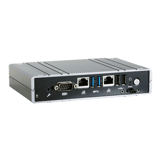
Front View
Rear View
Note:
The system offers another SKU with a different combination of display outputs: VGA + 2 Micro HDMI. It also
supports dual-display and triple-display functions: VGA + 2 Micro HDMI or DVI + 2 Mini DP.
DFI reserves the right to change the specifi cations at any time prior to the product's release. For the latest revision and details of the
installation process, please refer to the user's manual.
Package Contents
Panel
LAN 2
Mic-in
HDD LED
COM 1
(blue)
Antenna hole
DC-in
Mini DisplayPort
(DVI-D signal)
1
www.dfi .com
Reset Switch
LAN 1
Power Button
Status LED
(blue)
USB 3.0
USB 2.0
Remote Power
Switch
Antenna hole
Line-out
COM 2
DVI-I
(green)
Advertisement
Table of Contents

Related Manuals for DFI EC800-AL


Summary of Contents for DFI EC800-AL
-
Page 1: Package Contents
VGA + 2 Micro HDMI or DVI + 2 Mini DP. DFI reserves the right to change the specifi cations at any time prior to the product's release. For the latest revision and details of the installation process, please refer to the user's manual. -
Page 2: Removing The Chassis Cover
Removing the Chassis Cover Please observe the following guidelines and follow the procedure to open the system. 1. Make sure the system and all other peripheral devices connected to it have been powered off. 2. Disconnect all power cords and cables. 3. -
Page 3: Installing An M.2 Card
Installing an M.2 Card The system is equipped with two M.2 sockets, supporting one M.2 22x42mm (B key) and one M.2 22x30mm (AE key) form factor. To install a 42mm M.2 card: 1. Align the notch at the edge of the M.2 card with the key in the connector. 2. - Page 4 To install a 30mm M.2 card: 1. Align the notch at the edge of the M.2 card with the key in the connector. 2. Insert the M.2 card into the connector. 3. Push down on the other end of the M.2 card and use the provided mounting screw (the shorter one) to secure the card on the system board.
- Page 5 To install both 42mm and 30mm M.2 cards: 1. Align the notch at the edge of the 30mm M.2 card with the key in the connector. 2. Insert the 30mm M.2 card into the connector. 3. Push down on the other end of the card and place the plastic spacer on top of the card.
- Page 6 Installing a Mini PCIe or an mSATA Card The system board is equipped with 1 Mini PCIe slot. 1. Grasp the Mini PCIe card by its edges and align the notch of the PCIe card with the key in the connector on the system board. 2.
-
Page 7: Board Layout And Jumper Settings
Board Layout and Jumper Settings COM 1 LAN 2 Power LAN 1 USB 2.0 MIC-in Realtek Intel PCIe/SATA WGI211AT ALC262 USB 3.0 JP6 JP1 Clear CMOS Buzzer SMBus (J19) Power on/off (J11) Battery Intel WGI211AT Standby LED DDR4 Intel Atom ®...
Need help?
Do you have a question about the EC800-AL and is the answer not in the manual?
Questions and answers