Table of Contents
Advertisement
Quick Links
Advertisement
Table of Contents

Related Manuals for DFI EC70B-SU


Summary of Contents for DFI EC70B-SU
- Page 1 EC70B-SU User’s Manual A-464-M-2008 Chapter 1 Introduction www.dfi.com...
-
Page 2: Copyright
Product names or trademarks appearing in this manual are for identification purpose only and ance could void the user’s authority to operate the equipment. are the properties of the respective owners. Shielded interface cables must be used in order to comply with the emission limits. Chapter 1 Introduction www.dfi.com... -
Page 3: Table Of Contents
Security ..............................40 Specifications ......................7 Boot ................................42 Exit ................................43 Getting to Know the EC70B-SU ................8 Chapter 8 - Supported Software ........... 45 Mechanical Dimensions ..................9 Chapter 9 - Intel AMT Settings ..........53 Chapter 2 - Getting Started ............. 10 Chapter 3 - Installing the Devices......... -
Page 4: About This Manual
About this Manual Static Electricity Precautions An electronic file of this manual can be obtained from the DFI website at www.dfi.com. It is quite easy to inadvertently damage your PC, system board, components or devices even To download the user’s manual from our website, please go to “Support” > “Download Center.”... -
Page 5: Safety Precautions
• Unplug the power cord before removing the system chassis cover for installation or servic- ing. After installation or servicing, cover the system chassis before plugging the power cord. • 1 EC70B-SU system unit • Mounting screws for M.2 and Mini PCIe modules •... -
Page 6: Chapter 1 - Introduction
Chapter 1 Chapter 1 - Introduction Key Features Overview Model Name EC70B-SU Processor ® 6th Generation Intel Core processors, BGA 1356 Four LAN ports (two of them are PoE ports) Six COM ports Display VGA (or DP++ available upon request) -
Page 7: Specifications
Operating: Random 5~500Hz, IEC68-2-64 (3G) RS232 (or 8-bit DIO) Non-Operating: Sine 10~500Hz, IEC68-2-6 (3G) - Two USB 3.0 Type A ports - One VGA port (or an optional DP++ on the back panel) - One wireless module antenna hole Chapter 1 Introduction www.dfi.com... -
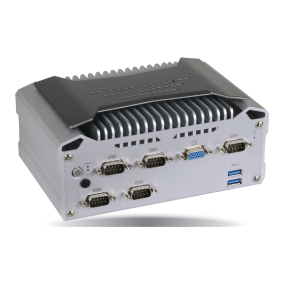
Page 8: Getting To Know The Ec70B-Su
Getting to Know the EC70B-SU Line-out USB 3.0 USB 3.0 Front View COM 3 LAN 1 LAN 2 Mic-in HDMI Status LED (blue) COM 2 COM 4/ 8-bit DIO COM 1 Power with LED (green) Power-on Switch HDD LED Reset... -
Page 9: Mechanical Dimensions
Chapter 1 Mechanical Dimensions Chassis Dimensions Motherboard Dimensions 115.00 Front View 103.20 98.20 82.00 184.00 18.00 8.00 0.00 Left View Right View Rear View Chapter 1 Introduction www.dfi.com... -
Page 10: Chapter 2 - Getting Started
Please refer to your operating system manual for instructions on installing an operating system. Installing the Drivers The system requires you to install drivers for some devices to operate properly. Refer to the Supported Software chapter for instructions on installing the drivers. Chapter 2 Getting Started www.dfi.com... -
Page 11: Chapter 3 - Installing The Devices
4. Use the provided mounting screw to secure the card on the system board. Standoff Chassis screw 4. Lift the cover to open the system. The M.2 socket on the expansion board is readily accessible after removing the bottom cover. M.2 socekt M.2 Type 2242 card Chapter 3 Installing the Devices www.dfi.com... -
Page 12: Installing A Mini Pcie Card
The system also has a half-size Mini PCIe slot that can accommodate either a Mini PCIe or an mSATA card. Refer to jumper settings for signal selection for this slot. Remove these screws to detach the expansion board from the main board Chapter 3 Installing the Devices www.dfi.com... -
Page 13: Chapter 4 - Jumper Settings
2. Set jumper pins 2 and 3 to On. Wait for a few seconds and set the jumper back to its de- fault setting, pins 1 and 2 On. 3. Now plug the power cord and power on the system. Chapter 4 Jumper Settings www.dfi.com... -
Page 14: Mini Pcie/Sata Signal Select
The system board uses JP1 and JP2 to select between RS232 serial communication or 8-bit DIO for the DB-9 connector (COM 4) at the rear panel. Important: You cannot use COM 4 and DIO at the same time. Please set JP1 and JP2 together. Chapter 4 Jumper Settings www.dfi.com... -
Page 15: Chapter 5 - Ports And Connectors
The DP port is a digital display interface used to connect a display device such as a computer monitor. It is used to transmit audio and video simultaneously. The interface, which is devel- oped by VESA, delivers higher performance than any other digital interfaces. Chapter 2 Hardware Installation Chapter 5 Ports and Connectors www.dfi.com... -
Page 16: Usb Ports
The system board is equipped with four onboard USB 3.0 ports (USB 1-4). USB devices allow data exchange between your computer and a wide range of simultaneously accessible external Plug and Play peripherals. Chapter 2 Hardware Installation Chapter 5 Ports and Connectors www.dfi.com... -
Page 17: Com (Serial) Ports
COM 1 and COM 2. DIO5 DIO6 BIOS Setting DIO7 Configure the serial ports in the “Advanced” menu (Super I/O submenu) of the BIOS. Refer to Chapter 7 for more information. Chapter 2 Hardware Installation Chapter 5 Ports and Connectors www.dfi.com... -
Page 18: Rj45 Lan Ports
Install the audio driver. Refer to the Chapter 8 for more information. Blinking Data Activity Green 100Mbps connection Link Orange 1Gbps connection Driver Installation Install the LAN drivers. Refer to Chapter 8 for more information. Chapter 2 Hardware Installation Chapter 5 Ports and Connectors www.dfi.com... -
Page 19: I/O Connectors
Configure the Serial ATA drives in the Advanced menu (“SATA Configuration” submenu) of the By connecting a proprietary expansion board to this connector, the system’s I/O connectivity can BIOS. Refer to Chapter 7 for more information. be expanded. Chapter 2 Hardware Installation Chapter 5 Ports and Connectors www.dfi.com... -
Page 20: Front Panel Connector
PWR_BTN SUS_LED RESET_BTN HDD_LED Pin Pin Assignment Pin Pin Assignment HDD Power Power Button PWR_BTN HDD_LED Ground Ground Ground Power LED PWR_LED RESET_BTN RST Signal Ground Ground SUS_LED SUS LED Chapter 2 Hardware Installation Chapter 5 Ports and Connectors www.dfi.com... -
Page 21: Standby Power Led
• Danger of explosion if battery incorrectly replaced. • Replace only with the same or equivalent type recommend by the manufacturer. • Dispose of used batteries according to local ordinance. Chapter 2 Hardware Installation Chapter 5 Ports and Connectors www.dfi.com... -
Page 22: Com (Serial) Ports (Expansion Board)
Configure the serial ports in the “Advanced” menu (XCT5-2LPSE2C802U submenu) of the BIOS. Refer to Chapter 7 for more information. Driver Installation Install the LAN driver. Refer to Chapter 8 for more information. Chapter 2 Hardware Installation Chapter 5 Ports and Connectors www.dfi.com... -
Page 23: Digital I/O Connector (Expansion Board)
The M.2 Type 2280 (B Key) slot can be inserted with a SATA SSD card with the form factor of 42mm, 60mm or 80mm (default). DIO3 DIO4 DIO5 DIO6 DIO7 Chapter 2 Hardware Installation Chapter 5 Ports and Connectors www.dfi.com... -
Page 24: Display Interfaces (Expansion Board)
Configure the display devices in the Advanced menu (“Video Configuration” submenu) of the BIOS. Refer to Chapter 7 for more information. Driver Installation Install the graphics driver. Refer to Chapter 8 for more information. Chapter 2 Hardware Installation Chapter 5 Ports and Connectors www.dfi.com... -
Page 25: Usb Ports (Expansion Board)
If you are using the Wake-On-USB Keyboard/Mouse function for 2 USB ports, the +5V_standby power source of your power supply must support ≥1.5A. For 3 or more USB ports, the +5V_standby power source of your power supply must support ≥2A. Chapter 2 Hardware Installation Chapter 5 Ports and Connectors www.dfi.com... -
Page 26: Chapter 6 - Mounting Options
Chapter 6 Chapter 6 - Mounting Options Use the provided mounting screws to attach the wall mount brackets to both sides on the bottom of the system. Wall Mount The wall mount kit includes the following: Mounting screw • 2 Wall mount brackets •... - Page 27 Chapter 6 VESA Mount Attach the VESA mount bracket A to the back of your display using four screws as shown in the picture below. Note: The system unit used in the following illustrations may not resemble the actual one. These illustrations are for reference only.
- Page 28 Chapter 6 DIN Rail Mount Align the mounting holes on the system and the mounting holes on the bracket, and then use the screws removed in step 1 to secure the bracket in place. Note: 3. The 3 mounting holes on the bracket are used to affix the DIN-rail mount clip to the The system unit used in the following illustrations may not resemble the actual one.
-
Page 29: Chapter 7 - Bios Setup
“Press DEL to run setup” will appear on the screen. If the message disappears before you respond, restart the system or press the “Reset” button. You may also restart the system by pressing the <Ctrl> <Alt> and <Del> keys simultaneously. Chapter 7 BIOS Setup www.dfi.com... -
Page 30: Main
23. Minute displays minutes from 00 to 59. Second displays seconds from 00 to 59. System Date The date format is <month>, <date>, <year>. Month displays the month, from Janu- ary to December. Date displays the date, from 1 to 31. Year displays the year, from 1980 to 2099. Chapter 7 BIOS Setup www.dfi.com... - Page 31 Specify what state the system should be in when power is re-applied after a power fail- ure (G3, the mechanical-off, state). S0 State The system is in working state. S5 State The system is in soft-off state. Chapter 7 BIOS Setup www.dfi.com...
- Page 32 Auto mode: Automatic selection PCI: PCI graphics devices IGFX: IGFX (internal graphics) devices PEG: PCIe graphics devices Internal Graphics Enable, disable or automatically detect the internal graphics. Always Enabled PEG Enable or disable the PCIe graphics devices. Chapter 7 BIOS Setup www.dfi.com...
- Page 33 Control the detection of the high-definition audio devices. Disabled High-definition audio devices will be unconditionally disabled. Enabled High-definition audio devices will be unconditionally enabled. Auto High-definition audio devices will be enabled if present and disabled otherwise. Chapter 7 BIOS Setup www.dfi.com...
- Page 34 M.2/CFast: Controls the SATA signal of the M.2 (default) or the CFast (optional) socket. SATA Port 1: Controls the SATA signal of the half-size mini PCIe slot. SATA Port 2: Controls the SATA signal of the SATA port on the system board. Chapter 7 BIOS Setup www.dfi.com...
- Page 35 Controls the PCIe signal of the full-size Mini PCIe slot. Mini PCIe Slot-2 (half) Controls the PCIe signal of the half-size Mini PCIe slot. Extend I/O PCIe_1 Extend I/O PCIe_2 Controls the PCIe signal of the extended I/O connector. Chapter 7 BIOS Setup www.dfi.com...
- Page 36 PCIe Speed Me Fw Image Re-Flash Select the speed of the PCI Express Root Port: Auto, Gen1 (2.5 GT/s), Gen2 (5 GT/s) Enable or disable Intel Management Engine firmware flashing. ® or Gen3 (8 GT/s). Chapter 7 BIOS Setup www.dfi.com...
- Page 37 Enable this serial port. Clears all ME related configurations without requiring a password on the next boot. Type Choose RS232, RS422 or RS485 (Peer-to-Peer) for the serial port type for COM port 1 and 2. Chapter 7 BIOS Setup www.dfi.com...
- Page 38 USB and LAN ports. Or enable the ERT support to not allow the system to consume power in S4 (hibernate) and S5 (soft-off ) states. The default is disabled. Note: WOL (wake-on-LAN) will be disabled if ERP Support is enabled. Chapter 7 BIOS Setup www.dfi.com...
- Page 39 The section allows you to configure the COM ports on the expansion board. Serial Port 1 (COM 5) and Serial Port 2 (COM 6) Enable or disable each serial port. Disable Disable this serial port. Enable Enable this serial port. Chapter 7 BIOS Setup www.dfi.com...
-
Page 40: Security
If you select to set the supervisor password, this option will be shown. Enable or disable the system to require password at boot. • Disable: Disable and deactivate TPM. • Enable: Enable and activate TPM. Clear TPM Remove all TPM ownership contents. Chapter 7 BIOS Setup www.dfi.com... - Page 41 32 characters. Storage Password Setup Page Set the storage password for each detected device. The following configuration options will be shown: (Device Name) Select this option to set a password for the selected device. Chapter 7 BIOS Setup www.dfi.com...
-
Page 42: Boot
PXE Boot to LAN (Legacy Boot Type)/PXE Boot Capability (Dual Boot Type) has the highest boot priority. Enable or disable Preboot eXecution Environment (PXE) boot to LAN. USB Boot Enable or disable booting to USB boot devices. Chapter 7 BIOS Setup www.dfi.com... -
Page 43: Exit
Select this field and press <Enter> to exit BIOS setup and save your changes. Load Optimal Defaults Select this field and press <Enter> to load the optimal defaults. Discard Changes Select this field and press <Enter>to exit the BIOS setup without saving your changes. Chapter 7 BIOS Setup www.dfi.com... - Page 44 MAC address should be burned Initializing Current BIOS Model name: SU25x or not. New BIOS Model name: SU25x Current BIOS version: 68.08A New BIOS version: 68.08A Updating Block at FFFFF000h 100% 100% C:\SU25x>_ Chapter 7 BIOS Setup www.dfi.com...
-
Page 45: Chapter 8 - Supported Software
Chapter 8 - Supported Software The system requires you to install drivers for some devices to operate properly. To download the latest driver, please go to the DFI Download Center: http://www.dfi.com/DownloadCenter Once you are in the Download Center page, select your product or type the model name and click "Search"... - Page 46 Click “Next”. 4. Please wait while the instal- lation is in progress. 2. Read the license agreement, and then click “Yes”. 5. Click “Restart Now” to allow the new software installa- tion to take effect. Chapter 8 Supported Software www.dfi.com...
- Page 47 2. Read the license agree- 5. Click “Yes, I want to restart ment, and then click “Yes”. this computer now”, and then click “Finish”. Restarting the system will allow the new software installation to take effect. Chapter 8 Supported Software www.dfi.com...
- Page 48 “Finish”. 2. Click “I accept the terms in the license agreement” if you accept the agreement, and then click “Next”. 3. Select the program features you want to install, and then click “Next”. Chapter 8 Supported Software www.dfi.com...
- Page 49 2. Read the license agreement, and then click “Yes”. 3. Click “Restart Now“ to restart your computer when 3. Wait while the setup is installing the installation is complete. the driver. After the installation is complete, click “Finish”. Chapter 8 Supported Software www.dfi.com...
- Page 50 1. You are about to install the driver. Click “Next” to continue. 4. Please wait while the prod- uct is being installed. 2. Read the license agree- ment, and then click “Next”. 5. After the installation is complete, click “Finish”. Chapter 8 Supported Software www.dfi.com...
- Page 51 “Finish”. Click “I accept the terms in the License Agreement” if you agree with Restart the system to allow the new the terms in the agreement and then software installation to take effect. click “Next”. Chapter 8 Supported Software www.dfi.com...
- Page 52 5. Setup is now installing the driver. 3. Read the file information and then click “Next”. 4. Setup is ready to install the driver. 6. Click “Finish” to exit the setup. Click “Next” to begin the installation. Chapter 8 Supported Software www.dfi.com...
-
Page 53: Chapter 9 - Intel Amt Settings
It protects the network from threats at the source by proactively blocking incoming threats, reactively containing infected clients before they impact the network, and proactively alerting when critical software agents are removed. 3. In the “Active Management Technology Support” menu, select “Enabled” for “Intel AMT Support”. Chapter 9 Intel AMT Settings www.dfi.com... - Page 54 Copyright(C) 2003-16 Intel Corporation. All Rights Reserved MAIN MENU MEBx Login > Intel (R) ME General Settings > Intel (R) AMT Configuration MEBx Exit Intel(R) ME Password [↑↓] = Move Highlight [Enter] = Select Entry [Esc]= Exit Chapter 9 Intel AMT Settings www.dfi.com...
- Page 55 Intel(R) Management Engine BIOS Extension v11.0.0.0008/Intel(R) ME v11.8.50.3399 Copyright(C) 2003-16 Intel Corporation. All Rights Reserved MAIN MENU > Intel (R) ME General Settings > Intel (R) AMT Configuration MEBx Exit [↑↓] = Move Highlight [Enter] = Select Entry [Esc]= Exit Chapter 9 Intel AMT Settings www.dfi.com...
- Page 56 > User Consent Password Policy <Anytime> > Network Setup Activate Network Access Unconfigure Network Access <Full Unprovision> > Remote Setup And Configuration > Power Control [↑↓] = Move Highlight [Enter] = Select Entry [Esc]= Exit Chapter 9 Intel AMT Settings www.dfi.com...
- Page 57 <Full Unprovi- Disabled sion> Enabled > Remote Setup And Configuration > Power Control [↑↓] = Move Highlight [Enter] = Select Entry [Esc]= Exit [↑↓] = Move Highlight [Enter] = Complete Entry [Esc]= Discard Changes Chapter 9 Intel AMT Settings www.dfi.com...
- Page 58 < Enabled> Storage Redirection <Enabled> KVM Feature Selection <Enabled> NONE Disabled Enabled [↑↓] = Move Highlight [Enter] = Complete Entry [Esc]= Discard Changes [↑↓] = Move Highlight [Enter] = Complete Entry [Esc]= Discard Changes Chapter 9 Intel AMT Settings www.dfi.com...
- Page 59 > Remote Setup And Configuration > Power Control Default Password Only During Stepup And Configuration Anytime [↑↓] = Move Highlight [Enter] = Select Entry [Esc]= Exit [↑↓] = Move Highlight [Enter] = Complete Entry [Esc]= Discard Changes Chapter 9 Intel AMT Settings www.dfi.com...
- Page 60 Shared/ Dedicated FQDN <Shared> Dynamic DNS Update <Disabled> Dynamic DNS Update <Disabled> Computer Domain Name Disabled Enabled [Enter] = Complete Entry [Esc]= Discard Changes [↑↓] = Move Highlight [Enter] = Complete Entry [Esc]= Discard Changes Chapter 9 Intel AMT Settings www.dfi.com...
- Page 61 Unconfigure Network Access > Remote Setup And Configuration Full Unprovision > Power Control [↑↓] = Move Highlight [Enter] = Complete Entry [Esc]= Discard Changes [↑↓] = Move Highlight [Enter] = Complete Entry [Esc]= Discard Changes Chapter 9 Intel AMT Settings www.dfi.com...
- Page 62 > RCFG > TLS PKI > TLS PKI Provisioning Mode: PKI Provisioning server address [↑↓] = Move Highlight [Enter] = Select Entry [Esc]= Exit [↑↓] = Move Highlight [Enter] = Select Entry [Esc]= Exit Chapter 9 Intel AMT Settings www.dfi.com...
- Page 63 PKI DNS Suffix > Manage Hashes This will activate Remote Condigura- tion. Continue: (Y/N) Disabled Enabled [↑↓] = Move Highlight [Enter] = Select Entry [Esc]= Exit [↑↓] = Move Highlight [Enter] = Select Entry [Esc]= Exit Chapter 9 Intel AMT Settings www.dfi.com...
- Page 64 Activate Network Access Unconfigure Network Access <Full Unprovision> > Remote Setup And Configuration > Power Control [↑↓] = Move Highlight [Enter] = Select Entry [Esc]= Exit [↑↓] = Move Highlight [Enter] = Select Entry [Esc]= Exit Chapter 9 Intel AMT Settings www.dfi.com...
- Page 65 This configurations are effective only after AMT provisioning has started Intel (R) ME ON in Host Sleep States <Mobile: ON in S0, ME Wake in S3, S4-5 (AC only)> Idle Timeout 65535 Timeout Value (1-65535) 65535 <ENTER> = Complete Entry [ESC]= Discard Changes Chapter 9 Intel AMT Settings www.dfi.com...
Need help?
Do you have a question about the EC70B-SU and is the answer not in the manual?
Questions and answers