Table of Contents
Advertisement
Quick Links
Advertisement
Table of Contents

Related Manuals for DFI EC70A-SU-394


Summary of Contents for DFI EC70A-SU-394
- Page 1 EC70A-SU User’s Manual A44711911 Chapter 1 Introduction www.dfi.com...
-
Page 2: Copyright
Product names or trademarks appearing in this manual are for identification purpose only and Shielded interface cables must be used in order to comply with the emission limits. are the properties of the respective owners. Chapter 1 Introduction www.dfi.com... -
Page 3: Table Of Contents
Chapter 4 - Jumper Settings ..........13 Clear CMOS Data ....................13 Auto Power-on Select ..................13 Mini PCIe Signal/ SATA Select .................14 COM4/DIO Select .....................14 Chapter 5 - Ports and Connectors ........15 Front Panel I/O Ports ..................15 Chapter 1 Introduction www.dfi.com... -
Page 4: About This Manual
After installation or servicing, cover the system chassis before plugging the power cord. Battery: • Danger of explosion if battery incorrectly replaced. • Replace only with the same or equivalent type recommend by the manufacturer. • Dispose of used batteries according to local ordinance. Chapter 1 Introduction www.dfi.com... -
Page 5: Safety Precautions
• Disconnect the system from the DC outlet before cleaning. Use a damp cloth. Do not use liquid or spray detergents for cleaning. Chapter 1 Introduction www.dfi.com... -
Page 6: Chapter 1 - Introduction
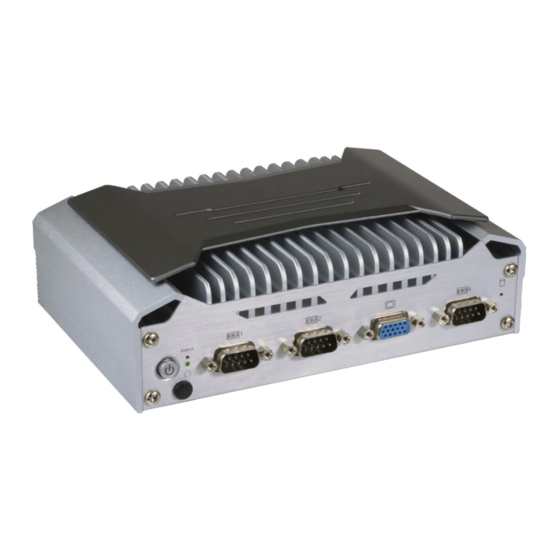
HDMI (or DP upon request) Audio Microphone and Line-out 4 USB 3.0 Type A ports Power 15~36V DC-in COM 4/ 8-bit DIO (by jumper switch) Front View Power Switch Power-on button and distant power-on switch Rear View Chapter 1 Introduction www.dfi.com... -
Page 7: Specifications
- One Line-out and one Mic-in ports - One HDMI port - Four USB 3.0 Type A ports - Two RJ45 LAN ports - One 15~36V DC-in jack - One distant power on/off switch - Two Wi-Fi module antenna holes Chapter 1 Introduction www.dfi.com... -
Page 8: Getting To Know The Ec70A-Su
You should feel resistance (due to a pin on the right) if the cable is not HDD State HDD present or HDD not present activity inserted correctly. Angled-corner Aligning side Align this edge with the LED Behavior Blink Angled-corner left side of the connector (left) (up) Chapter 1 Introduction www.dfi.com... -
Page 9: Mechanical Dimensions
Chapter 1 Mechanical Dimensions Chassis Dimensions Motherboard Dimensions Front View 57.00 181.60 115.00 103.20 98.20 Left View Right View 18.00 8.00 0.00 Rear View Chapter 1 Introduction www.dfi.com... -
Page 10: Chapter 2 - Getting Started
Installing the Drivers The system package includes a CD disk. The CD includes drivers that must be installed to pro- vide the best system performance. Refer to the Supported Software chapter for instructions on installing the drivers. Chapter 2 Getting Started www.dfi.com... -
Page 11: Chapter 3 - Installing The Devices
4. Place the SATA drive bay with the installed HDD back to the system and connect the SATA cable to the SATA connectors on the system board. SATA power connector SATA connector SATA drive bay SATA power connector SATA data connector SATA drive bay Mounting screw SATA cable Mounting screw Chapter 3 Installing the Devices www.dfi.com... -
Page 12: Installing A Mini Pcie Card
Mounting Screw Note: The system also has a half-size Mini PCIe slot that can accommodate either a Mini PCIe or an mSATA card. Refer to jumper settings for signal selection for this slot. Chapter 3 Installing the Devices www.dfi.com... -
Page 13: Chapter 4 - Jumper Settings
2. Set JP4 pins 2 and 3 to On. Wait for a few seconds and set JP4 back to its default setting, pins 1 and 2 On. 3. Now plug the power cord and power on the system. Chapter 4 Jumper Settings www.dfi.com... -
Page 14: Mini Pcie Signal/ Sata Select
The system board uses JP1 and JP2 to select between RS232 serial communication or 8-bit DIO for the DB-9 connector (COM 4) at the rear panel. mSATA (default). Important: You cannot use COM 4 and DIO at the same time. Please set JP1 and JP2 together. Chapter 4 Jumper Settings www.dfi.com... -
Page 15: Chapter 5 - Ports And Connectors
• Four USB 3.0 ports - One (COM4) supports only RS232 with optional 8-bit DIO • Mic-in/line-out jack • VGA port • Two RJ45 LAN ports • HDD LED (blue) • 15~36V DC-in Chapter 2 Hardware Installation Chapter 5 Ports and Connectors www.dfi.com... -
Page 16: 15~36V Dc-In
Configure the display devices in the Advanced menu (“Video Configuration” submenu) of the BIOS. Refer to Chapter 7 for more information. Driver Installation Install the graphics driver. Refer to Chapter 8 for more information. Chapter 2 Hardware Installation Chapter 5 Ports and Connectors www.dfi.com... -
Page 17: Usb Ports
The system board is equipped with four onboard USB 3.0 ports (USB 1-4). USB devices allow data exchange between your computer and a wide range of simultaneously accessible external Plug and Play peripherals. Chapter 2 Hardware Installation Chapter 5 Ports and Connectors www.dfi.com... -
Page 18: Com (Serial) Ports
COM 1 and COM 2. DIO_6 BIOS Setting DIO_7 Configure the serial ports in the “Advanced” menu (Super I/O submenu) of the BIOS. Refer to Chapter 7 for more information. Chapter 2 Hardware Installation Chapter 5 Ports and Connectors www.dfi.com... -
Page 19: Rj45 Lan Ports
The LAN ports allow the system board to connect to a local area network using a network Driver Installation hub. Install the audio driver. Refer to the Chapter 8 for more information. Driver Installation Install the LAN drivers. Refer to Chapter 8 for more information. Chapter 2 Hardware Installation Chapter 5 Ports and Connectors www.dfi.com... -
Page 20: I/O Connectors
Chapter 7 for the designated SATA port of this slot. BIOS Setting Configure the Serial ATA drives in the Advanced menu (“SATA Configuration” submenu) of the BIOS. Refer to Chapter 7 for more information. Chapter 2 Hardware Installation Chapter 5 Ports and Connectors www.dfi.com... -
Page 21: Front Panel Connector
When the system’s power is on, this LED will be lit. When the system is in the S1 (POS - Pow- er On Suspend) state, it will blink every second. When the system is in the S3 (STR - Suspend To RAM) state, it will blink every 4 seconds. Chapter 2 Hardware Installation Chapter 5 Ports and Connectors www.dfi.com... -
Page 22: Standby Power Led
• Danger of explosion if battery incorrectly replaced. • Replace only with the same or equivalent type recommend by the manufacturer. • Dispose of used batteries according to local ordinance Chapter 2 Hardware Installation Chapter 5 Ports and Connectors www.dfi.com... -
Page 23: Chapter 6 - Mounting Options
Chapter 6 Chapter 6 - Mounting Options Use the provided mounting screws to attach the wall mount brackets to both sides on the bottom of the system. Wall Mount The wall mount kit includes the following: Mounting screw • 2 Wall mount brackets •... - Page 24 Chapter 6 VESA Mount Attach the VESA mount bracket A to the back of your display using four screws as shown in the picture below. Note: The system unit used in the following illustrations may not resemble the actual one. These illustrations are for reference only.
- Page 25 Chapter 6 DIN Rail Mount Align the mounting holes on the system and the mounting holes on the bracket, and then use the screws removed in step 1 to secure the bracket in place. Note: 3. The 3 mounting holes on the bracket are used to affix the DIN-rail mount clip to the The system unit used in the following illustrations may not resemble the actual one.
-
Page 26: Chapter 7 - Bios Setup
“Press DEL to run setup” will appear on the screen. If the message that field and press <Enter>. disappears before you respond, restart the system or press the “Reset” button. You may also restart the system by pressing the <Ctrl> <Alt> and <Del> keys simultaneously. Chapter 7 BIOS Setup www.dfi.com... -
Page 27: Main
23. Minute displays minutes from 00 to 59. Second displays seconds from 00 to 59. System Date The date format is <month>, <date>, <year>. Month displays the month, from Janu- ary to December. Date displays the date, from 1 to 31. Year displays the year, from 1980 to 2099. Chapter 7 BIOS Setup www.dfi.com... - Page 28 The system is in soft-off state. Note: For the “After G3” setting to take effect, make sure that the “AC Power Loss” op- tion is set to “Always on” in “SIO NUVOTON6106D” of the “Advanced” menu. Chapter 7 BIOS Setup www.dfi.com...
- Page 29 Enable, disable or automatically detect the internal graphics. Always Enabled PEG Enable or disable PCIe Graphics devices. Boot display Set the display device combination during system boot. The options may vary depend- ing on the “Boot Type” selected in the “Boot” menu. Chapter 7 BIOS Setup www.dfi.com...
- Page 30 Control the detection of the high-definition audio devices. Enable or disable Serial ATA controllers. Disabled High-definition audio devices will be unconditionally disabled. Enabled High-definition audio devices will be unconditionally enabled. Auto High-definition audio devices will be enabled if present and disabled otherwise. Chapter 7 BIOS Setup www.dfi.com...
- Page 31 Serial ATA Port 1 and 2 Enable or disable each serial ATA port. SATA 1: Controls the SATA signal of the half-size mini PCIe slot. SATA 2: Controls the SATA signal of the SATA port on the system board. Chapter 7 BIOS Setup www.dfi.com...
- Page 32 Chapter 7 PCI Express Configuration This section configures the settings of PCI Express root ports. PCI Express Root Port Enable or disable each PCI Express Root Port. Chapter 7 BIOS Setup www.dfi.com...
- Page 33 This section configures flashing of the Intel ® Management Engine. PCIe Speed Me Fw Image Re-Flash Select the speed of the PCI Express Root Port: Auto, Gen1, Gen2 or Gen3. Enable or disable Intel Management Engine firmware flashing. ® Chapter 7 BIOS Setup www.dfi.com...
- Page 34 Clears all ME related configurations without requiring a password on the next boot. Enable Enable this serial port. Type Choose RS232, RS422 or RS485 (Peer-to-Peer) for the serial port type for COM port 1 and 2. Chapter 7 BIOS Setup www.dfi.com...
- Page 35 AC power loss event. When set to Always on, the system’s status will be power-on after an AC power loss event. This item is only working when JP7 (auto power on) jumper is set as 2-3 on (automatic power-on via AC power). Chapter 7 BIOS Setup www.dfi.com...
-
Page 36: Security
If you select to set the supervisor password, this option will be shown. Enable or disable the system to require password at boot. • Disable: Disable and deactivate TPM. • Enable: Enable and activate TPM. Clear TPM Remove all TPM ownership contents. Chapter 7 BIOS Setup www.dfi.com... -
Page 37: Boot
The first device in the list PXE Boot to LAN has the highest boot priority. Enable or disable Preboot eXecution Environment (PXE) boot to LAN. USB Boot Enable or disable booting to USB boot devices. Chapter 7 BIOS Setup www.dfi.com... -
Page 38: Exit
Select this field and press <Enter> to exit BIO setup and save your changes. Load Optimal Defaults Select this field and press <Enter> to load the optimal defaults. Discard Changes Select this field and press <Enter>to exit the BIOS setup without saving your changes. Chapter 7 BIOS Setup www.dfi.com... - Page 39 MAC address should be burned Initializing Current BIOS Model name: SU25x or not. New BIOS Model name: SU25x Current BIOS version: 68.08A New BIOS version: 68.08A Updating Block at FFFFF000h 100% 100% C:\SU25x>_ Chapter 7 BIOS Setup www.dfi.com...
-
Page 40: Chapter 8 - Supported Software
Insert the DVD into a DVD-ROM drive. The autorun screen (Mainboard Utility DVD) will appear. If the “Autorun” does not automatically start, please go directly to the root directory of the DVD and double-click “Setup”. For Windows 10 Chapter 8 Supported Software www.dfi.com... - Page 41 To install the utility, click “Intel Chipset Software Installation Utility” on the main menu. 1. Setup is ready to install the utility. Click “Next” to continue. 2. Read the license agreement ,and then click “Yes”. Chapter 8 Supported Software www.dfi.com...
- Page 42 (while WinSAT is running) before the Windows 7/Windows 8.1/Windows 10 desktop appears. The “blank screen” period is the time Windows is testing the graphics performance. 2. Read the license agree- ment, and then click “Yes”. Chapter 8 Supported Software www.dfi.com...
- Page 43 Restarting the system will allow the new software installation to take effect. 5. Click “Yes, I want to restart this computer now”, and then click “Finish”. Restarting the system will allow the new software installation to take effect. Chapter 8 Supported Software www.dfi.com...
- Page 44 5. After the installation is complete, click “Finish”. 2. Click “I accept the terms in the license agreement”, and then click “Next”. 3. Select the program features you want installed, and then click “Next”. Chapter 8 Supported Software www.dfi.com...
- Page 45 3. Click “Restart Now“ to restart your computer when the installation is complete. To install the driver, click “Kernel-Mode Driver” on the main menu. 1. Click “Yes“ to install the update. 2. The update is being installed now. Chapter 8 Supported Software www.dfi.com...
- Page 46 1. Setup is ready to install the driver. Click “Next” to continue. 4. Please wait while the prod- uct is being installed. 2. Read the license agree- ment, and then click “Next”. 5. After the installation is complete, click “Finish”. Chapter 8 Supported Software www.dfi.com...
- Page 47 1. Setup is ready to install the driver. 4. The wizard is ready to begin the installation. Click “Install” to start installing the program. 2. Click “Next” to continue. 5. Please wait while the program features are being installed. Chapter 8 Supported Software www.dfi.com...
- Page 48 The screenshot displayed above is for illustrative purpose only, and may not resemble the actual screen. The HW Utility has the following tabs: Information, HW Health, HW Health set, Watchdog, DIO and Backlight. Click each tab to access its respective function. Backlight Chapter 8 Supported Software www.dfi.com...
- Page 49 Click “Next” to continue. 4. Setup is currently installing the driver. After the installation is complete, click “Next”. 2. Read the license agreement, and then click “Yes”. 5. After the installation is complete, click “Finish”. Chapter 8 Supported Software www.dfi.com...
- Page 50 1. Setup is ready to install the driver. Click “Next”. 4. Setup is ready to install the driver. Click “Next” to continue. 2. Read the license agreement care- fully. Click “I accept the terms in the License Agreement”, and then click “Next”. Chapter 8 Supported Software www.dfi.com...
- Page 51 Chapter 8 5. Setup is now installing the driver. 6. Click “Finish” to exit the setup. Chapter 8 Supported Software www.dfi.com...
- Page 52 1. Setup is now extracting files. 4. Click “Finish” to exit the setup program. 2. Read the license agreement care- fully. Click “I have read and accept the terms of the License Agree ment”, and then click “Install”. Chapter 8 Supported Software www.dfi.com...
- Page 53 2. The setup program is now ready to install the utility. Click “Next” to continue. 6. Click “Install” to begin the installation. 3. Click “I accept the terms in the license agreement”, and then click “Next”. Chapter 8 Supported Software www.dfi.com...
- Page 54 10. Click “Yes” to restart your system. soft Visual C++ package prior to installing the utility. Click “Install” to start the installation. 8. The setup program is currently installing the Microsoft Visual C++ package. 9. Click “Finish”. Chapter 8 Supported Software www.dfi.com...
- Page 55 To install the reader, click “Adobe Acrobat Reader 9.3” on the main menu. 1. Click “Next” to install or click “Change Destination Folder” to select a different folder for installation. 2. Click “Install” to begin install- ing the program. 3. Click “Finish” to exit the installa- tion. Chapter 8 Supported Software www.dfi.com...
-
Page 56: Chapter 9 - Intel Amt Settings
It protects the network from threats at the source by proactively blocking incoming threats, reactively containing infected clients before they impact the network, and proactively alerting when critical software agents are removed. 3. In the “Active Management Technology Support” menu, select “Enabled” for “Intel AMT Support”. Chapter 9 Intel AMT Settings www.dfi.com... - Page 57 Copyright(C) 2003-15 Intel Corporation. All Rights Reserved. MAIN MENU MEBx Login > Intel (R) ME General Settings > Intel (R) AMT Configuration MEBx Exit Intel(R) ME Password [↑↓] = Move Highlight [Enter] = Select Entry [Esc]= Exit Chapter 9 Intel AMT Settings www.dfi.com...
- Page 58 Intel(R) Management Engine BIOS Extension v11.0.0.0005/Intel(R) ME v11.0.0.1205 Copyright(C) 2003-15 Intel Corporation. All Rights Reserved. MAIN MENU > Intel (R) ME General Settings > Intel (R) AMT Configuration MEBx Exit [↑↓] = Move Highlight [Enter] = Select Entry [Esc]= Exit Chapter 9 Intel AMT Settings www.dfi.com...
- Page 59 > User Consent Password Policy <Anytime> > Network Setup Activate Network Access Unconfigure Network Access <Full Unprovision> > Remote Setup And Configuration > Power Control [↑↓] = Move Highlight [Enter] = Select Entry [Esc]= Exit Chapter 9 Intel AMT Settings www.dfi.com...
- Page 60 <Full Unprovi- Disabled sion> Enabled > Remote Setup And Configuration > Power Control [↑↓] = Move Highlight [Enter] = Select Entry [Esc]= Exit [↑↓] = Move Highlight [Enter] = Complete Entry [Esc]= Discard Changes Chapter 9 Intel AMT Settings www.dfi.com...
- Page 61 < Enabled> Storage Redirection <Enabled> KVM Feature Selection <Enabled> NONE Disabled Enabled [↑↓] = Move Highlight [Enter] = Complete Entry [Esc]= Discard Changes [↑↓] = Move Highlight [Enter] = Complete Entry [Esc]= Discard Changes Chapter 9 Intel AMT Settings www.dfi.com...
- Page 62 > Remote Setup And Configuration > Power Control Default Password Only During Stepup And Configuration Anytime [↑↓] = Move Highlight [Enter] = Select Entry [Esc]= Exit [↑↓] = Move Highlight [Enter] = Complete Entry [Esc]= Discard Changes Chapter 9 Intel AMT Settings www.dfi.com...
- Page 63 Shared/ Dedicated FQDN <Shared> Dynamic DNS Update <Disabled> Dynamic DNS Update <Disabled> Computer Domain Name Disabled Enabled [Enter] = Complete Entry [Esc]= Discard Changes [↑↓] = Move Highlight [Enter] = Complete Entry [Esc]= Discard Changes Chapter 9 Intel AMT Settings www.dfi.com...
- Page 64 Unconfigure Network Access > Remote Setup And Configuration Full Unprovision > Power Control [↑↓] = Move Highlight [Enter] = Complete Entry [Esc]= Discard Changes [↑↓] = Move Highlight [Enter] = Complete Entry [Esc]= Discard Changes Chapter 9 Intel AMT Settings www.dfi.com...
- Page 65 > RCFG > TLS PKI > TLS PKI Provisioning Mode: PKI Provisioning server address [↑↓] = Move Highlight [Enter] = Select Entry [Esc]= Exit [↑↓] = Move Highlight [Enter] = Select Entry [Esc]= Exit Chapter 9 Intel AMT Settings www.dfi.com...
- Page 66 PKI DNS Suffix > Manage Hashes This will activate Remote Condigura- tion. Continue: (Y/N) Disabled Enabled [↑↓] = Move Highlight [Enter] = Select Entry [Esc]= Exit [↑↓] = Move Highlight [Enter] = Select Entry [Esc]= Exit Chapter 9 Intel AMT Settings www.dfi.com...
- Page 67 Activate Network Access Unconfigure Network Access <Full Unprovision> > Remote Setup And Configuration > Power Control [↑↓] = Move Highlight [Enter] = Select Entry [Esc]= Exit [↑↓] = Move Highlight [Enter] = Select Entry [Esc]= Exit Chapter 9 Intel AMT Settings www.dfi.com...
- Page 68 This configurations are effective only after AMT provisioning has started Intel (R) ME ON in Host Sleep States <Mobile: ON in S0, ME Wake in S3, S4-5 (AC only)> Idle Timeout 65535 Timeout Value (1-65535) 65535 <ENTER> = Complete Entry [ESC]= Discard Changes Chapter 9 Intel AMT Settings www.dfi.com...
-
Page 69: Appendix A - Watchdog Sample Code
;Select watchdog timer register DX,AL DX,4FH AL,10H ;Set watchdog timer value DX,AL DX,4EH AL, F0H ;Select watchdog Control Register DX,AL DX,4FH AL,02H ;Set Watchdog Control Value DX,AL ;---------------------------------------------------------------- ;(1) Exit extended function mode ;---------------------------------------------------------------- DX,4EH AL,AAH DX,AL Appendix A Watchdog Sample Code www.dfi.com... -
Page 70: Appendix B - System Error Message
The BIOS reports memory test fail if the memory has error(s). VIDEO selection. FLOPPY DISK(S) fail (80) Unable to reset floppy subsystem. FLOPPY DISK(S) fail (40) Floppy type mismatch. Hard Disk(s) fail (80) HDD reset failed. Hard Disk(s) fail (40) HDD controller diagnostics failed. Appendix B System Error Message www.dfi.com... -
Page 71: Appendix C - Troubleshooting Checklist
4. There is not enough space left on the diskette. Use another diskette with adequate storage 4. Adjust the brightness of the display by turning the monitor’s brightness control knob. space. Appendix C Troubleshooting Checklist www.dfi.com... - Page 72 Nothing happens when a key on the keyboard was pressed. 1. Make sure the keyboard is properly connected. 2. Make sure there are no objects resting on the keyboard and that no keys are pressed dur- ing the booting process. Appendix C Troubleshooting Checklist www.dfi.com...
Need help?
Do you have a question about the EC70A-SU-394 and is the answer not in the manual?
Questions and answers