Advertisement
Quick Links
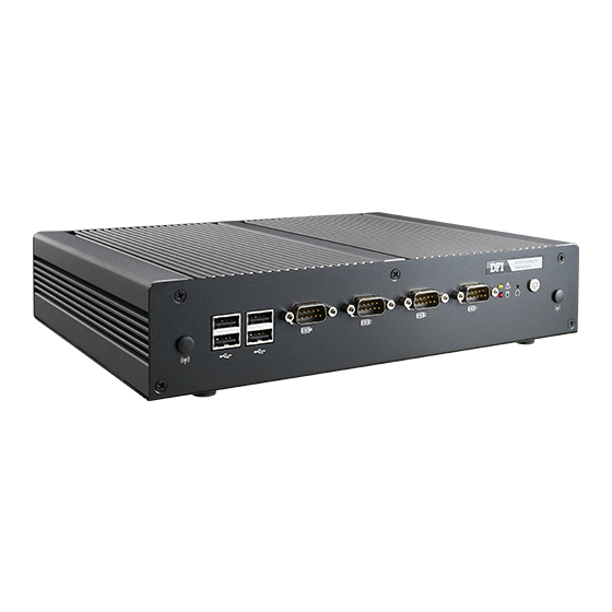
EC200/210/220/221-BT Installation Guide
• 1 system unit
• 1 HDD drive bay kit
• Terminal blocks
This QIG is based on versions that may not resemble your actual products. For
the latest revision and more details of the installation process, please refer to the
user's manual on the website.
Package Contents
www.dfi.com
1
Advertisement

Related Manuals for DFI EC200-BT


Summary of Contents for DFI EC200-BT
- Page 1 • 1 HDD drive bay kit • Terminal blocks This QIG is based on versions that may not resemble your actual products. For the latest revision and more details of the installation process, please refer to the user's manual on the website. www.dfi.com...
- Page 2 Installing a 2.5" SATA Drive 1. First, use the 5 provided mounting screws to secure the protective plate in place on the system board. Mounting Screws Protective plate Heat-dissipating plate...
- Page 3 2. Align the mounting holes of the SATA drive with the mounting holes on the HDD brackets and then use the provided mounting screws to secure the drive in place. SATA drive HDD bracket Mounting screw...
- Page 4 3. Place the SATA drive (with HDD brackets) into the system. Align the mounting holes on the HDD brackets with the mounting holes on the heat-dissipating plate and then use the provided mounting screws to secure the drive in place. Mounting hole HDD bracket Mounting screw...
- Page 5 4. Connect A to the SATA data/power connector on the SATA drive, B and C to the SATA power connector and the SATA data connector respectively on the system board. SATA power connector (B) SATA data/power connector (A) SATA data connector (C) SATA data/power connector (A) SATA power connector (B) SATA data connector (C)
-
Page 6: Board Layout And Jumper Settings
Board Layout and Jumper Settings Power Button Reset Auto Power-on Mini PCIe/mSATA Select (JP12) Reset Power Select (JP3) Mini PCIe CPU Fan Front Panel Line-out Buzzer Realtek ALC888 SMBus SATA SATA 2.0 Power 1 LAN 1 (optional) Front (JP23) Audio SATA 1/mSATA Signal Standby Power LED (JP14) - Page 7 5. When COM 4 RS232/422/485 is selected, JP29 and JP30 must be set in RS422 Full Duplex/RS485 3-5, 4-6 On accordance to JP21. 6. When installing one DDR3L SODIMM only, make sure to install it into the SODIMM 1 socket. www.dfi.com 934-EC2000-1A0G A37522952...
Need help?
Do you have a question about the EC200-BT and is the answer not in the manual?
Questions and answers