
Related Manuals for DFI EC510


Summary of Contents for DFI EC510
- Page 1 EC510/511-KH User’s Manual Preliminary Version A55900933 Chapter 1 Introduction www.dfi.com...
-
Page 2: Copyright
Product names or trademarks appearing in this manual are for identification purpose only and ance could void the user’s authority to operate the equipment. are the properties of the respective owners. Shielded interface cables must be used in order to comply with the emission limits. Chapter 1 Introduction www.dfi.com... -
Page 3: Table Of Contents
USB Ports ....................27 9~36V DC-in ....................27 Specifications ................7 I/O Connectors ..............28 Getting to Know the EC510/EC511-KH ........8 PS/2 KB/MS Connector ................28 Mechanical Dimensions ............9 SATA (Serial ATA) Connectors ..............28 SATA (Serial ATA) Power Connectors ............29 Chapter 2 - Getting Started ........ -
Page 4: About This Manual
An electronic file of this manual is included in the CD. If not, you can download it and other It is quite easy to inadvertently damage your PC, system board, components or devices even product related documentation from our website at www.dfi.com. before installing them in your system unit. Static electrical discharge can damage computer components without causing any signs of physical damage. -
Page 5: Safety Precautions
• Unplug the power cord before removing the system chassis cover for installation or servic- ing. After installation or servicing, cover the system chassis before plugging the power cord. • 1 EC510/EC511-KH system unit • 1 CD disk includes: Drivers/Manual •... -
Page 6: Chapter 1 - Introduction
Chapter 1 Chapter 1 - Introduction Key Features Overview Model Name EC510/EC511-KH Processor ® 7th Generation Intel Core processors Chipset Intel CM238, Intel QM175 Chipset ® ® ® 6 LAN ports (or 4 PoE + 2 LAN ports) 5 COM ports... -
Page 7: Specifications
Chapter 1 Specifications Expansion Processor 7th Generation Intel Core Processors, BGA1440 Socket • 1 x PCIe x16 (EC511-KH only) or 1 x PCI (EC510-KH only) ® ® ® • Intel Xeon Processor E3-1535M v6, Quad Core, 8M Cache, 3.1GHz • 1 x M.2 2280 M key (PCIe x4 NVMe, Intel optane memory support) (4.2GHz), 45W... -
Page 8: Getting To Know The Ec510/Ec511-Kh
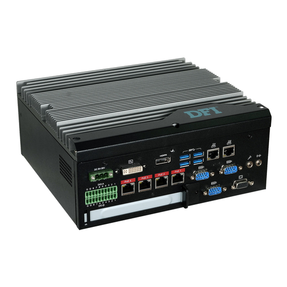
Chapter 1 Getting to Know the EC510/EC511-KH Front I/O Ports Power Button with LED (Green) Press to power on or power off the system. Front Panel Reset Button Press to reset the system. Power Button COM 2 COM 1 USB 2.0... -
Page 9: Mechanical Dimensions
Chapter 1 Mechanical Dimensions Chassis Dimensions Motherboard Dimensions 209.55 Rear View Gold finger PCIE X4 Gold finger PCIE X16 mini PCIe Left View Right View 235.00 Front View Chapter 1 Introduction www.dfi.com... -
Page 10: Chapter 2 - Getting Started
Installing the Drivers The system package includes a CD disk. The CD includes drivers that must be installed to pro- vide the best system performance. Refer to the Supported Software chapter for instructions on installing the drivers. Chapter 2 Getting Started www.dfi.com... -
Page 11: Chapter 3 - Installing The Devices
The 6 mounting screws on the left and right sides and bottom of the system are used to secure the cover to the chassis. Remove these screws and put them in a safe place for later use. Chassis screw Chassis screw Chassis screw Chapter 3 Installing the Devices www.dfi.com... -
Page 12: Installing A Sodimm
If you plan to install only one SODIMM, install it in the DIMM1 socket (lower one and farther from the center of the mainboard). The SODIMM sockets can only accept DDR4 memory modules. Please do not install other types of memory modules. Chapter 3 Installing the Devices www.dfi.com... -
Page 13: Installing A 2.5" Sata Drive
SATA cables Mounting screws SATA power connector Note: Connect SATA cables before affixing the SATA drive on the HDD bracket as the HDD bracket would prevent access to the SATA connectors of the drive. Chapter 3 Installing the Devices www.dfi.com... -
Page 14: Installing A Mini Pcie Card
2. Secure the card on the mainboard with the provided mounting screw. SIM 2 If the Mini PCIe card has antennas, route the antennas to the antenna holes on the front chassis of the device. Antenna holes Front bezel mounting screw Chapter 3 Installing the Devices www.dfi.com... -
Page 15: Installing An M.2 Card
Flip the cover up to open it Close the slot's cover and lock the slot by pushing the white latch outward. Mounting Screw Close the cover and lock it Chapter 3 Installing the Devices www.dfi.com... -
Page 16: Installing A Pci Or Pcie Expansion Card
Note: Slot plate Mounting screw and bracket The EC511-KH has one PCIe x16 slot with the H120-1E riser card, whereas the EC510- KH has one PCI slot with the H320-1P riser card. Chapter 3 Installing the Devices www.dfi.com... -
Page 17: Installing A Cpu
LGA 1151 socket comes with the protective cap. 5. Unlock the socket by pushing the load lever down, move it sideways until it is released from the retention tab, and then lift the load lever up. Alignment key Gold triangular mark Chapter 3 Installing the Devices www.dfi.com... - Page 18 10. Close the load plate and push the load lever down to lock it under the retention tab. While closing the load plate, slide the front edge of the load plate under the retention tab. Retention knob Chapter 3 Installing the Devices www.dfi.com...
-
Page 19: Chapter 4 - Jumper Settings
2. Set the jumper pins 2 and 3 to On. Wait for a few seconds and set JP4 back to its default setting, pins 1 and 2 On. 3. Now plug the power cord and power on the system. Chapter 4 Jumper Settings www.dfi.com... -
Page 20: Com1/Com2 Rs232 Power Select
JP8 (for COM1) and JP7 (for COM2) are used to configure Serial COM ports to pure RS232 or RS232 with power. The pin functions (Pin1 and Pin 9) of COM1 and COM2 will vary according to JP8’s and JP7’s setting respectively. Chapter 4 Jumper Settings www.dfi.com... -
Page 21: Com1/Com2 Rs232/422/485 Select
You can also configure the RS485 auto flow mecha- must be set in accordance to JP16. nism through the BIOS setup utility. For more information, please refer to Chapter 7. Chapter 4 Jumper Settings www.dfi.com... -
Page 22: Com3/Com4 Rs232/422/485 Select
When COM3 RS232/422/485 is selected, JP12 and JP18 must be set in accor- RS232 (default) RS422 Full Duplex/RS485 dance to JP5. And when COM4 RS232/422/485 is selected, JP6 and JP19 must be set in accordance to JP13. Chapter 4 Jumper Settings www.dfi.com... -
Page 23: Dio High/Low Select (Dio 0~3)
2-3 Pull-down 2-3 Pull-down 1-2 Pull-up 1-2 Pull-up 5V/5V_Standby 5V/5V_Standby JP3 is used to set the digital pins 0~3 to pull-up or pull-down. JP2 is used to set the digital pins 4~7 to pull-up or pull-down. Chapter 4 Jumper Settings www.dfi.com... -
Page 24: Chapter 5 - Ports And Connectors
BIOS Setting • Two USB 2.0 ports Configure the onboard USB in the Advanced menu (“USB Configuration” submenu) of the • Two RS232/422/485 serial COM ports BIOS. Refer to Chapter 7 for more information. Chapter 5 Ports and Connectors www.dfi.com... -
Page 25: Com (Serial) Ports
You should feel resistance (due to a pin on the right) if the cable is not inserted correctly. For detailed instructions, see https://youtu.be/SUj07rfN5l8. Angled-corner Aligning side Align this edge with the Angled-corner left side of the connector (left) (up) Chapter 5 Ports and Connectors www.dfi.com... -
Page 26: Rj45 Lan Ports
Configure the display devices in the Advanced menu (“Video Configuration” submenu) of the BIOS. Refer to the Chapter 7 for more information. Driver Installation Install the graphics driver. Refer to Chapter 8 for more information. Chapter 5 Ports and Connectors www.dfi.com... -
Page 27: Usb Ports
3.0 ports at the rear panel and 2 USB 2.0 ports at the front panel of the system unit. damage to the system board. • BIOS Setting Configure the onboard USB in the Advanced menu (“USB Configuration” submenu) of the BIOS. Refer to Chapter 7 for more information. Chapter 5 Ports and Connectors www.dfi.com... -
Page 28: I/O Connectors
SATA drive’s power connector in order to provide power to the drive. BIOS Setting Configure the Serial ATA drives in the Advanced submenu (“SATA Configuration” section) of the BIOS. Refer to Chapter 7 for more information. Chapter 5 Ports and Connectors www.dfi.com... -
Page 29: Sata (Serial Ata) Power Connectors
SATA power connector and the other end to your storage device. multiple device bus that allows multiple chips to connect to the same bus and enable each one to act as a master by initiating data transfer. Chapter 5 Ports and Connectors www.dfi.com... -
Page 30: Rear Audio Connector
Mic-in Jack This jack is used to connect an external microphone. DIO 3 DIO 4 Driver Installation DIO 5 Install the audio driver. Refer to the Chapter 8 for more information. DIO 6 DIO 7 Chapter 5 Ports and Connectors www.dfi.com... -
Page 31: 12V Dc-Out
On Suspend) state, it will blink every second. When the system is in the S3 (STR - Suspend To RAM) state, it will blink every 4 seconds. Pin Pin Assignment Pin Pin Assignment HDD Power LED Power HDD-LED Signal PWR-LED LED Power Ground Signal RST Signal Ground RESET SW ATX-SW N.C. Signal Chapter 5 Ports and Connectors www.dfi.com... -
Page 32: Expansion Slots
DPC_CTRL_CLK (N/A) LPC_AD3 PCI Express x4 Slot DPC_CTRL_DATA (N/A) LPC_LDRQ1# Reserved DPC_HPD (N/A) Install PCI Express cards such as network cards or other cards that comply to the PCI Ex- press specifications into this slot. Chapter 5 Ports and Connectors www.dfi.com... -
Page 33: Lpc Connector
The Low Pin Count Interface was defined by Intel Corporation to facilitate the industry’s transition ® SMB_CLK_RESUME DFI Board ID_0 towards legacy free systems. It allows the integration of low-bandwidth legacy I/O components SMB_DATA_RESUME DFI Board ID_1 within the system, which are typically provided by a Super I/O controller. Furthermore, it can be... -
Page 34: Lan Ports (Daughter Board)
Digital I/O Connector Pins DIO-A DIO-B PoE LED Speed LED LED Behavior Description LED Behavior Description DIO1 DIO1 The system is not 10Mbps connection DFI INC. powered on. MODEL: XCT3-4LPSEGD REV: SILK_TOP DIO2 DIO2 DATE: 08/22/2017 DFI INC. Green Supplying power over... -
Page 35: Chapter 6 - Mounting Options
The following illustration shows the location and dimension of the holes for mounting the device 1. The wall mounting holes are located on the bottom of the system unit. onto a wall or rack . Mounting hole Ø8.50 Ø3.60 251.80 262.80 Mounting hole Chapter 6 Mounting Options www.dfi.com...
Need help?
Do you have a question about the EC510 and is the answer not in the manual?
Questions and answers