Simrad AP50 Installation Manual
Autopilot standard system
Hide thumbs
Also See for AP50:
- Instruction manual (188 pages) ,
- Installation manual (142 pages) ,
- Operator's manual (62 pages)

Related Manuals for Simrad AP50


Summary of Contents for Simrad AP50
-
Page 1: Installation Manual
Installation manual Simrad AP50 Autopilot Standard system English Sw.1.3 www.simrad-yachting.com A brand by Navico - Leader in Marine Electronics... - Page 2 INSTALLATION MANUAL SIMRAD AP50 Autopilot Standard System 20222469/B Sw. 1.3. English...
- Page 3 Simrad AP50 Autopilot About this document Rev. A First issue. The former Instruction Manual P/N 20221032 Rev. C has been splitted into one Operator Manual and one Installation Manual. Manuals are updated according to software version 1.3. S9 Steering Lever has been included. QS50 and JD5X are added to the Technical Specifications.
- Page 4 Simrad AP50 autopilot. Great care has been taken to simplify the installation set-up of the AP50; however, an autopilot is a complex electronic system and particular attention has to be paid by the installer. Please take the time to read this manual together with the...
-
Page 5: Table Of Contents
How to Use This Manual................2 INSTALLATION ....................3 General......................3 Unpacking and Handling ................3 Installation Index ....................3 Determining System Configuration..............4 AP50 System Layout ..................5 RF300 Rudder Feedback Unit ................6 RF45X Rudder Feedback Unit ...............8 Electrical Connection ..................9 Mechanical Alignment .................11 RF14XU Rudder Feedback Unit ..............12 Mechanical mounting ...................12... - Page 6 General Information JP21 Jack Point Installation ................29 2.12 RC25 Rate Compass ..................30 RFC35 Fluxgate Compass ................32 2.13 FU50 Steering Lever ..................33 2.14 TI51 Thruster Interface.................33 2.15 AD50 Analog Drive..................33 2.16 S9 Steering Lever ..................33 Mounting ......................33 Connection....................34 2.17 Remote Control.....................36 2.18 JS10 Joystick ....................37 2.19 S35 NFU Steering Lever ................37 2.20 F1/2 Remote Control ..................38...
- Page 7 Simrad AP50 Autopilot Interface Set-up.....................54 Sea Trial......................61 Compass Calibration................62 Compass Offset..................63 Set Thrust Direction, On/Off Thruster.............64 Thruster Calibration, Analog Thruster.............64 Thruster zero ....................64 Direction and Maximum Thrust STBD, Analog Thruster .......65 Direction and Maximum Thrust PORT, Analog Thruster .......65 Minimum Thrust, Analog Thruster............66 Speed source ....................66...
- Page 8 Minimum thrust ..................87 Thruster hyst ....................87 Thruster Drive..................88 Response delay..................88 SPARE PARTS LIST ..................91 TECHNICAL SPECIFICATIONS ..............95 AP50 Autopilot System ................95 AP50 Control Unit..................96 AP51 Remote Control ..................97 Junction Units ....................98 RC25 Rate Compass ..................99 CDI35 Course Detector Interface ...............100 CD100A Course Detector................101...
- Page 9 Simrad AP50 Autopilot 6.11 RF14XU Rudder Feedback Unit ..............103 6.12 NI300X NMEA Interface ................105 6.13 TI51 Thruster Interface................106 6.14 AD50 Analog Drive..................106 6.15 R3000X Remote Control ................107 6.16 S9 Steering Lever ..................108 6.17 Environmental Protection ................109 6.18 NMEA Sentences ..................109 INDEX.........................111...
-
Page 10: General Information
“master unit” in order for the installation to be approved. Simrad has no responsibility for the incorrect installation or use of the AP50 autopilot, so it is essential for the person in charge of the installation to be familiar with the relevant requirements as well as with the contents of this manual, which covers correct installation and use. -
Page 11: How To Use This Manual
This manual is intended as a reference guide for installing and commissioning the Simrad AP50 autopilot. Great care has been taken to simplify the set-up and operation and of the AP50; however, an autopilot is a complex electronic system. It is affected by sea conditions, speed of the vessel, and vessel hull shape and size. -
Page 12: Installation
A visual inspection should be made to ensure that the equipment has not been damaged during shipment and that all parts are present according to the packing list. A standard scope of supply for a basic AP50 system may include: • A control unit with standard installation accessories •... -
Page 13: Determining System Configuration
6. Interface set-up for Junction Unit, GI51 and NI300X (if installed; see page 54) 7. Select the settings in the User Set-up Menu for Speed source, Compass source, and Nav. source. Ref. AP50 Operator Manual. 8. Perform the autopilot pre-tests at the dock (refer to Operation... -
Page 14: Ap50 System Layout
(refer to Technical Specifications, section 4, beginning on page 91. Robnet Extension Cable (10m) is available from your Simrad distributor. Refer to the Spare Parts List on page 91 for part numbers. 2.5 AP50 System Layout... -
Page 15: Rf300 Rudder Feedback Unit
Simrad AP50 Autopilot 2.6 RF300 Rudder Feedback Unit (For small to medium size vessels) The RF300 Rudder feedback unit mounts close to the rudders, and is mechanically linked to the rudder tiller arm or rudder quadrant (refer to Figure 2-2 on page 7 for the recommended mounting arrangement). -
Page 16: Junction Unit
Installation Figure 2-2 RF300 Rudder Feedback Unit Mounting (019356) Note ! Due to space limitations, it may be necessary to cut the length of the transmitter rod to move the RF300 closer to the rudderpost. Tighten the mounting screws for both the RF300 Rudder Feedback Unit and the transmitter rod ball joint. -
Page 17: Rf45X Rudder Feedback Unit
However, it can be mounted with the shaft pointing downwards for increased convenience. The deflection can then be inverted in the AP50 software or as illustrated in Figure 2-5 on page 9. An “upside-down” installation will make access to the unit more efficient as it can be opened without moving it from the mounting base. -
Page 18: Electrical Connection
Installation Electrical Connection Use a twisted-pair shielded cable, 0.5 mm (AWG20), between the breakout box and the J50 Junction Unit. The cable length is not critical but should be kept to a minimum. The cable should be connected to the junction unit according to Figure 2-5. - Page 19 Simrad AP50 Autopilot Figure 2-6 RF45X Connection to RI9 Rudder Angle Indicators and RI35 Mk2 (optional) The above connection diagram shows how to connect an RI9 Rudder Angle Indicator to a system with RF45X Rudder Feedback Unit. For connection of RI35 Mk2 Rudder Angle Indicators only, refer to the RI35 Mk2 manual.
-
Page 20: Mechanical Alignment
Installation Mechanical Alignment The purpose of this procedure is to find the zero point and to allow the feedback unit to operate within its active segment. If the unit operates outside this segment, there will be a feedback failure alarm. 1. -
Page 21: Rf14Xu Rudder Feedback Unit
Simrad AP50 Autopilot 2.8 RF14XU Rudder Feedback Unit Mechanical mounting Before installation, check that the alignment mark on the mounting plate agrees with the mark on the shaft. Bring the rudder to Midships position. The feedback unit should be mounted on a plane surface and secured by bolts through the three holes in the mounting plate. - Page 22 Installation The feedback unit has an external ground terminal an must have a proper ground connection to the hull. The grounding wire should be as short as possible and at least 10 mm wide. The RF14XU can be powered either from the rudder angle indicator supply (19-40V DC) or directly from the autopilot junction unit.
- Page 23 10, for +/-90˚ connect violet lead to terminal 10. White lead must remain connected. Figure 2-9 RF14XU Internal wiring Figure 2-10 shows how to connect the RF14XU Rudder Feedback Unit to an AP50 system with 24V autopilot supply. 20222469 / B...
- Page 24 J50 Vbat+ instead of J50 Supply+. Note ! This configuration is only for 24VDC. Figure 2-10 RF14XU connected to an AP50 system and optional rudder angle indicators Note ! The resistor R (0.5-1K, 0.5W) has to be mounted. The resistor is not supplied by Simrad.
-
Page 25: Final Check
Simrad AP50 Autopilot Final check After installation, the cable glands must be sealed with silicon to prevent water from seeping in. Also apply silicon grease to the gasket between the bottom and top cover. On the inside of the feedback unit cover, a piece of moisture protecting sponge is attached. -
Page 26: Grounding And Radio Frequency Interface (Rfi)
Table 2-1 Recommended Cable Sizes Grounding and Radio Frequency Interface (RFI) The AP50 system has excellent radio frequency interference protection and all units use the junction unit as a common ground/shield connection. The junction unit must therefore have a proper ground connection to the hull. -
Page 27: Junction Unit Terminals
Simrad AP50 Autopilot Provide sufficient wire length so that the plug-in terminals can be easily connected and disconnected. Pull out each terminal before connecting the wires. Remove all the strands before putting on the terminal cover. Junction Unit Terminals J50 Power Board Terminals... -
Page 28: Autopilot Mode Control (Auto/Standby Toggling)
STANDBY mode. The next pulse will bring the autopilot to AUTO mode, hence, when the AP50 is set for STBY (NFU) and the system select is shorted to GND, the AP50 display changes from showing STBY to show a blank segment with subtext “Disengaged”. -
Page 29: External Alarm (Wheelmark System)
The relation between drive units, drive unit voltage, input voltage, drive output, and interfacing to steering gear are shown in Table 2-2 and Table 2-3. The AP50 system detects whether a reversible motor or a solenoid is connected and outputs the correct drive signal automatically. - Page 30 Installation HYDRAULIC PUMPS RAM CAPACITY MODEL MOTOR JUNCTION FLOW MAX. PWR. MIN. MAX. VOLTS UNIT RATE AT 10 PRES- CONSUMP- SURE TION (cu. in.) (cu. in.) /min. (cu. in./min.) RPU80 80 (4.9) 250 (15.2) 800 (49) 2,5-6 A RPU160 160 (9.8) 550 (33.5) 1600 (98) 3-10 A...
-
Page 31: Connecting A Reversible Pump
Simrad AP50 Autopilot PREVIOUS MODELS Simrad Drive Input Drive output Interface to Drive Unit type unit voltage steering gear voltage (Mains) RPU100, 12, 24,32 Proportional Hydraulic RPU150, rate plumbing (Reversible hydraulic pump) MRD100 12, 24, 32 12V to clutch Chain/... -
Page 32: Connecting A Hydraulic Linear Drive
Installation Connecting a Hydraulic Linear Drive HYDRAULIC JUNCTION UNIT LINEAR DRIVE POWER PCB Drive engage Figure 2-16 Connecting a Hydraulic Linear Drive Connecting Solenoid Valves Solenoids (externally powered, common positive) JUNCTION UNIT POWER PCB SOLENOID VALVE Solenoid isolated Figure 2-17 Connecting Externally-powered Solenoids with a Common Positive Caution ! To prevent damage of the J50 Power PCB, ensure that the S1... -
Page 33: Solenoids (Externally Powered, Common Negative)
Simrad AP50 Autopilot Solenoids (externally powered, common negative) JUNCTION UNIT POWER PCB SOLENOID VALVE Solenoid isolated Figure 2-18 Connecting Externally-powered Solenoids with a Common Negative Caution ! To prevent damage of the J50 Power PCB, ensure that the S1 jumper switch on the Power PCB is set to position 2-3. -
Page 34: Control Unit
• Connect the Robnet cable(s) to the control unit connector(s) (see “Note!” on page 28). Optional Bracket mounting (This may be ordered separately from Simrad, part no. 20212130). Note ! When the control unit is bracket-mounted, it is not weatherproof from the back due to a breathing hole in the back cabinet. -
Page 35: Robnet Units And Robnet Network Cables
Figure 2-20 AP50 Bracket mounting Robnet Units and Robnet Network Cables The following Robnet units are available in a system: AP50 Control Unit, AP51 Remote Control, RC25 Rate Compass, FU50 Follow-Up lever, GI51 Gyro Interface, NI300X NMEA Interface, TI51 Thruster Interface and AD50 Analog Drive. - Page 36 55 (180’) 50 (165’) 45 (150’) 40 (130’) If the total length exceeds the recommended length, please contact your Simrad distributor on how to arrange the system to minimize the voltage drop. Examples of interconnecting Robnet units: CONTROL CONTROL CONTROL...
- Page 37 Simrad AP50 Autopilot See Table 2-5 for pin configuration and color code of the network cable. DO NOT MIX THE PINS AND THE CABLE COLORS! Note ! Apply a thin layer of pure Vaseline (petroleum jelly) on the connector threads and make sure the connectors are properly secured to the receptacle by the coupling ring.
-
Page 38: Ap51 Remote Control Connection
Installation AP51 Remote Control Connection If the AP51 Remote Control is part of the system, use the Robnet connector in a free receptacle (see Figure 2-21). Alternatively, cut the connector from the cable and connect the wires in parallel with the cable shown on Figure 2-23 using the same color code. -
Page 39: Rc25 Rate Compass
2.12 RC25 Rate Compass Figure 2-25 RC25 Rate Compass Mounting The heading sensor is the most important part of the AP50 system and great care must be taken in choosing the mounting location. The heading sensor can be mounted at any location where there is a minimum of magnetic interference and minimum movements. - Page 40 CONTROL UNIT Figure 2-26 RC25 Connection to AP50 Control Unit • Connect the Robnet connector to the AP50 Control Unit (or GI51 or NI300X if installed). • Alternatively, if there is no free receptacle, cut the connector from the cable and connect the wires in parallel with the wires going from the junction unit to the control unit.
-
Page 41: Rfc35 Fluxgate Compass
Simrad AP50 Autopilot JUNCTION UNIT RATE COMPASS JUNCTION UNIT MAIN PCB TB15 GREY PINK BROWN WHITE Bn Wht Robnet RC25 RATE COMPASS Figure 2-27 Alternative Connection to J50 Junction Unit Robnet Terminal • Change in the Installation Interface menu: Select FLUX = ROBNET. -
Page 42: Fu50 Steering Lever
2.14 TI51 Thruster Interface The TI51 Thruster Interface is designed to provide control signal for operating one thruster in an AP50 system by either on/off solenoid, continuous control, or Sauer Danfoss PVEM valve. Refer to separate manual for the TI51 Thruster Interface. -
Page 43: Connection
Simrad AP50 Autopilot Figure 2-29 S9 Steering Lever, bulkhead mounting Figure 2-30 S9 Steering Lever, panel mounting Connection If connected according to Figure 2-31, S9 can be used for NFU steering through J50 Junction Unit when the autopilot is in STBY mode and for course change in AUTO mode. - Page 44 Installation Figure 2-31 S9 connection to J50 Figure 2-32 Solenoid valves with priority steering, externally powered, common positive 20222469 / B...
-
Page 45: Remote Control
Simrad AP50 Autopilot Figure 2-33 Solenoid valves with priority steering, externally powered, common negative 2.17 Remote Control The R3000X Remote Control is weather proof and can be mounted outdoors in the supplied bracket that is fixed by four mounting screws. -
Page 46: Js10 Joystick
Installation 2.18 JS10 Joystick Refer to separate installation procedure for JS10 (document no. 20221610) 2.19 S35 NFU Steering Lever The S35 NFU Steering Lever may be mounted to the bulkhead or to a panel by two screws from the front. The cable is connected to the junction unit according to Figure 2-35. -
Page 47: F1/2 Remote Control
Figure 2-36 F1/2 Remote Control Connection 2.21 Interfacing to Optional Equipment (THD, Navigation Receiver, etc.) With the AP50 autopilot system, there are several options for connection to other equipment for data exchange: 1. The J50 Junction Unit includes two NMEA input/output ports and a Clock Data heading interface to Simrad and Furuno radars. -
Page 48: Single Nmea Input/Output
Installation Single NMEA input/output NAV RECEIVER JUNCTION UNIT OR PLOTTER MAIN PCB (NMEA talker) TB13 TB14 NMEA NMEA Input 1 Output1 NMEA listener RUDDER instr. COMPASS instr. RADAR Figure 2-37 Single NMEA Connection Double NMEA input/output JUNCTION UNIT MAIN PCB POWER PCB GPS or ECS TB13... -
Page 49: Input From "Nmea Compass
Simrad AP50 Autopilot Input from “NMEA Compass” A gyro compass or GPS compass (or other) with NMEA 0183 HDT (or HDG, HDM message) is connected to the J50/J50-40 Junction Unit NMEA Input2 terminal. JUNCTION UNIT POWER PCB NMEA COMPASS NMEA... -
Page 50: Analog Heading Repeater
GI51 Gyro Interface The GI51 Gyro Interface is required when a gyrocompass with geared synchro or stepper signal output is connected to the AP50. The GI51 is also required when a speed log signal with 200 pulses/NM is connected to the system. -
Page 51: Ni300X Nmea Interface Unit
Simrad AP50 Autopilot NI300X NMEA Interface Unit The NI300X NMEA Interface Unit is normally installed inside of a console or locker close to navigation receivers, radar, and instruments to keep the cables short. The unit does not have controls that need to be operated during installation or use, but you should be able to take the lid off for inspections and to view LED indication of received signals. -
Page 52: Cd100A Course Detector
Simrad and Furuno. The 12V output is designed for driving instruments with a total maximum load of 250 mA. Configuration for Simrad or Furuno is selected in the Installation Interface Menu (see page 61). CD100A Course Detector The owner may prefer to use the boat’s own compass. -
Page 53: Cdi35 Interface
Figure 2-45 CDI35 Interface Connections Note ! The CD100 is a previous model and its cable has a connector that must be cut off for connection in the AP50 system (e.g. to the GI51 or the CDI35). CD109 Course Detector For retrofit installations, a CD109 Course detector may be connected to the CDI35 according to Figure 2-46. -
Page 54: Software Set-Up Procedure
Some important points regarding the Installation Set-up values: • When the AP50 is delivered new from the factory, (AND ANY TIME AFTER A MASTER RESET OF MEMORIES SETUP REQUIRED... -
Page 55: Installation Menu
Simrad AP50 Autopilot stored in the memory of the AP50 system. No specific action is required to save the selected values to memory. Once the value is changed, it is stored until the next time the menu item is selected and changed. -
Page 56: Language Selection
NAV buttons. On new installations, and whenever a junction unit or software is replaced in an AP50 system, it is recommended that a Master Reset be performed as described under SERVICE in the Installation Menu (see page 77) prior to proceeding with the set- up procedure. - Page 57 Simrad AP50 Autopilot ENTER INSTALLATION MENU SYMBOLS INSTALLATION BY PRESSING AND HOLDING THE MENU NAV BUTTON FOR 5 SECONDS SELECT OR CONFIRM BY ROTARY COURSE SELECTOR PROCEED TO NEXT MENU ITEM LANGUAGE MENU BY PRESSING STBD BUTTON LANGUAGE ENGLISH DEUTSCH...
-
Page 58: Master Operation
Software Set-up Procedure Master Operation For vessel that comply with the European Marine Equipment directive, one control unit must be set for Master operation, if more than one control unit is connected. The other unit(s) is then automatically set as a “slave”. The system can only be switched DOCKSIDE off from the master unit (see also Operator Manual, Master Master operation... -
Page 59: Rudder Feedback Calibration
The clutch/bypass voltage is automatically set to coincide with the drive unit voltage. During the rudder test, the AP50 system will also automatically detect whether the drive unit is a reversible motor or whether it is solenoid operated. To change the voltage selection, rotate the course knob. -
Page 60: Rudder Calibration
Note ! If no adjustment has been made to the display readout (i.e. not turning the course knob), the AP50 will set the physical stop to 45°. “Max. rudder limit” will be set to 2° less. Note ! Rudder-zero may still be inaccurate and should be adjusted later during sea trial. -
Page 61: Rudder Test
DOCKSIDE clockwise. Rudder test ---- --------- drive Clutch --- -------- The AP50 will, after a few seconds, issue a series of PORT and Rudder limit Rudder deadband Thruster ---- STBD rudder commands, automatically verify correct rudder direction, detects minimum voltage for running, and reduce the rudder speed (reversing pumpset or proportional valves) if it exceeds the maximum acceptable speed for autopilot operation. -
Page 62: Rudder Limit
Software Set-up Procedure The Drive out (displayed in percentage) is the amount of maximum available voltage needed to achieve correct rudder speed when automatic steering (Maximum speed is used in NFU steering). It will be indicated on the screen whether a clutch is installed or not. -
Page 63: Rudder Deadband
Thruster direction and the Maximum thrust. Interface Set-up The AP50 system provides a flexible approach to the input of data from heading sensors and other external equipment. Identification of the type of equipment connected to the AP50 system is performed in the Interface Menu. - Page 64 This turn radius will allow the ship to turn before the waypoint is reached and enables the AP50 to follow a route seamlessly. Note ! Confirmation for course change by the user will not be required.
- Page 65 1 to 5 times/sec. on TX1 port. or VDR data HDT and RSA 5x/sec. Output RADAR Clock/data heading output to May select Simrad, Furuno, or radars Special** (for both J50 and NI300X) Automatic course change at waypoint will now occur during navigation in NAV mode.
- Page 66 (STBD) WIND J50-1 DEPTH J50-1 button. J50-1 INSTR J50-1 Input: RADAR SIMRAD ----- J50-1 J50-2 NI300-1 NI300-2 NI300-3 NI300-4 Note ! Upon completion of the Interface Set-up, the names of items to...
- Page 67 Simrad AP50 Autopilot Interface Set-up - Input Signal Set-up item Equipment Connected to terminal Assign hardware (abbrev. name) connected (name) (use one available from list) port to set-up item (* = default setting) GPS1 Not connected – – – –...
- Page 68 Software Set-up Procedure Set-up item Equipment Connected to terminal Assign hardware (abbrev. name) connected (use one available from list) port to set-up item (name) (* = default setting) GYRO2 Not connected – – – – * Connection to Robnet ROBNET ** J50, Power PCB NMEA I/P RX2+,RX2–...
- Page 69 Simrad AP50 Autopilot Set-up item Equipment Connected to terminal Assign hardware (abbrev. name) connected (use one available from list) port to set-up item (name) (* = default setting) FLUX1 Not connected – – – – RC25 Connection to Robnet ROBNET* Junction unit: HS+, HS–...
-
Page 70: Sea Trial
• Compass Offset (to offset the final compass heading readout) • Max/Minimum thrust, thrust direction and levels (only if thruster is selected) • Set cruising speed (in the AP50) • Set rudder zero (to indicate the precise midships position of the rudder) •... -
Page 71: Compass Calibration
1.2.02 Oct 29 2004 Compass Calibration This function will activate the automatic compass calibration procedure (for Simrad compasses connected through Robnet and through J50 Junction Unit Heading Sensor (HS) terminal, and compasses connected through GI51). Note ! If an optional magnetic compass is installed and connected to J50 or GI51, or if a gyrocompass, or other manufacturer’s... -
Page 72: Compass Offset
(STBY) button. S TB Y Note ! If an optional NMEA compass from Simrad or another manufacturer is installed, refer to the optional compass’ manual regarding calibration. Compass Offset The compass Offset feature allows you to correct for a constant compass heading offset. -
Page 73: Set Thrust Direction, On/Off Thruster
Simrad AP50 Autopilot Set Thrust Direction, On/Off Thruster (ONLY IF ON/OFF THRUSTER IS SELECTED, proceed to page 65 if continuous thruster or Danfoss thruster is selected) Rotate the course knob clockwise to activate the Set thrust SEATRIAL direction setting. Compass... -
Page 74: Direction And Maximum Thrust Stbd, Analog Thruster
Software Set-up Procedure Direction and Maximum Thrust STBD, Analog Thruster (ONLY IF CONTINUOUS THRUSTER OR DANFOSS SEATRIAL THRUSTER IS SELECTED) Thruster zero Maximum thrust STBD ---% Maximum thrust PORT ---% Minimum thrust Rotate the course knob clockwise to activate the Maximum thrust STBD setting. -
Page 75: Minimum Thrust, Analog Thruster
Simrad AP50 Autopilot Minimum Thrust, Analog Thruster (ONLY IF CONTINUOUS THRUSTER OR DANFOSS THRUSTER IS SELECTED) The Minimum thrust determines the amount of power (in % of SEATRIAL Thruster zero the maximum control signal) that is applied as the "first... -
Page 76: Set Cruising Speed
Software Set-up Procedure Set Cruising Speed Steer the boat at cruising speed. The speed is shown at the Set SEATRIAL cruising speed line. Rotate the course knob clockwise to Compass Flux1 Calibration Offset +005° confirm the cruising speed. Heading 288° Speed source Set cruising speed 15kt If Speed source is set to Man, adjust for actual cruising speed... -
Page 77: Adjust Rudder Angle/Set Rate Of Turn
Simrad AP50 Autopilot automatic modes (Ref. User Set-up in the Operator Manual). The Turn gain may also be readjusted (Refer to Turn Gain on page 85). Note ! The Set rate of turn function is only activated when using the course knob, NOT the Port and STBD buttons. -
Page 78: Manual Tuning
Run the boat at cruising speed. Rotate the course knob clockwise Set rudder zero Done Set rate of turn to activate the Manual Tuning. The AP50 will now control the 210 Done 000°/min Manual tuning steering of the boat. If another course is desired, rotate the... -
Page 79: Automatic Tuning
Simrad AP50 Autopilot While at cruising speed, adjust the Rudder value by turning the course knob until the autopilot keeps the boat on a steady course. Counter Rudder SEATRIAL Press the (STBD) button to display the set course. Make a 90°... - Page 80 Software Set-up Procedure Selecting the boat type and length has set default values for these parameters (Installation Dockside menu). Before doing any parameter tuning, check if the boat steers satisfactory with the default setting (can be checked as described under Manual Tuning or by normal Auto steering).
-
Page 81: Speed Response
Automatic tuning response from the main steering. Speed response From the Sea trial menu, select Speed response by rotating the course knob clockwise. The AP50 will now take control over the SEATRIAL ADJUST steering of the boat. If another course is desired (CTS), rotate the course knob until RUDDER 340 . -
Page 82: Providing User Training
• Set waypoints into each navigator connected to the system, and verify that the AP50 steers in NAV mode for each Nav. source. • Provide user training. - Page 83 Simrad AP50 Autopilot This page is intentionally left blank 20222469 / B...
-
Page 84: Advanced Settings
Select "SERVICE" by pressing the (STBD) button and confirm by rotating the course knob clockwise. “SYSTEM DATA” and “NMEA DATA” are test functions to analyze data processed by the AP50. SYSTEM DATA NMEA DATA NMEA PORT TEST To exit the menu, press any mode key (STBY, AUTO or NAV). -
Page 85: Nmea Data
---m Decoding The incoming signals are decoded according to a built-in priority table in the AP50. Cross Track Error and bearing information is taken from the NMEA messages with highest priority. For all data items, one of the following codes will be displayed: No data or no NMEA sentence containing the data needed at the input port. -
Page 86: Nmea Port Test (J50 Hardware)
Turn CCW Warning: Will restore factory clockwise. settings. New setup will be required STBY Exit the Installation Menu by pressing the (STBY) button to return to normal AP50 operation. 20222469 / B... -
Page 87: Settings Menu
Simrad AP50 Autopilot 4.2 Settings Menu Select SETTINGS in the Installation Menu by pressing the SETTINGS (STBD) button and confirm this by rotating the course knob STEERING THRUSTER clockwise. Two groups of settings are available; Steering and Thruster (only when thruster is installed). -
Page 88: Course Adjust
Advanced Settings The Autotrim value can be adjusted from 10 seconds to 400 seconds with the course knob. The default value depends on the boat length. The Autotrim parameter is reset every time the AUTO mode is entered or when a course change greater than approximately 20° is made by the course knob. -
Page 89: Drive Engage
Simrad AP50 Autopilot Drive engage This determines the use of the J50 Drive Engage port. The port voltage is the same as the selected Drive Unit voltage. Drive engage has the following different settings: Bypass/clutch: This port will activate (go high), in all modes except for STANDBY and DODGE hand-steering. -
Page 90: Drive Type
Advanced Settings Drive type This indicates the type of drive installed. The display will show “Motor”, “Solenoid”, “Proportional” or “Analog”, respectively. The reading is obtained from the Automatic rudder test under the Dockside menu. The set value may be changed here. Drive out Not applicable for “Analog”... -
Page 91: Rudder
Simrad AP50 Autopilot Rudder Rudder sets the rudder gain, which is the ratio between the commanded angle and the heading error. Default value depends on boat length. Range: 0.05 to 4.00. Counter rudder Counter Rudder is the parameter that counteracts for the effect of the boats turn rate and inertia. -
Page 92: Transition Speed
Planing boats may often have very different steering characteristics before and after planing. The same may apply for water jet driven boats at low and high speed. AP50 offers the possibility of using the Auto-Work mode values for Rudder and Counter Rudder at low speed. -
Page 93: Turn Mode
Simrad AP50 Autopilot Minimum Rudder 0.1° Rudder deadband 0.3° P-factor/Counter Rudder 1.0° Total rudder amount 5.3° Range: 0 to 10° in 0.1° increments Default: OFF Turn mode This allows for the selection of Rate of Turn (ROT) steering or Radius (RAD) steering. -
Page 94: Init Nav
Advanced Settings Init NAV Sets a firm or soft approach to the rhumb line when entering the NAV mode at the first leg. The approach angle is dependant (adaptive) on the distance (XTE) from the rhumb line and the boat speed. Range: Soft - Firm Default: Firm Turn Gain... -
Page 95: Thruster
Simrad AP50 Autopilot Thruster Select Thruster in the Settings menu by pressing the (STBD) SETTINGS button and confirm this by rotating the course knob clockwise STEERING THRUSTER (only available when Thruster is selected for steering). Thruster inhibit SETTINGS Thruster inhibit is a feature that will block the thruster from... -
Page 96: Minimum Thrust
Advanced Settings When operating in “Continuous” mode, the thruster gain setting determines the power from the thruster versus heading error. For higher values, the power increases with the same error signal. If the vessel tends to oscillate around set heading, the value should be decreased. -
Page 97: Thruster Drive
Simrad AP50 Autopilot Thruster Drive (Only applicable for Continuous and Danfoss thrusters) For On/Off thrusters, it is important to keep thruster activity to a minimum. TI51 therefore has a feature that adaptively adjusts the length of each thruster command to bring the vessel back on heading without over- or undershoot. - Page 98 Advanced Settings SETTINGS Displayed parameter Boat type (Default settings) Own boat Displacement Planing Waterjet Autotune Manual Dockside Menu Master Operation Boat length 0-50 feet 0-50 feet 0-50 feet Drive unit voltage Rudder limit 10° 10° 10° Rudder deadband AUTO AUTO AUTO Thruster - - - -...
- Page 99 Simrad AP50 Autopilot This page is intentionally left blank 20222469 / B...
-
Page 100: Spare Parts List
Spare Parts List 5 SPARE PARTS LIST AP50 Control Unit 20214045 AP50 Control Unit with accessories 20212247 Installation Accessories 20212130 Mounting Bracket ass’y 20211819 Protection Cover 20212213 AP50 Front Housing Ass’y 20211868 AP50 Board Ass'y 20212189 PROM (programmed) V..R.. AP51 Remote Control... - Page 101 Simrad AP50 Autopilot RF45X Rudder Feedback Unit 22011415 RF45X Rudder Feedback Unit 22011217 Mounting Kit 22011258 RF45X PCB Ass’y with Potentiometer 22011183 RF45 Transmission Link Ass’y 22011431 RF45X Ball Joint Ass’y 22504039 Transmission Lever RF14XU Rudder Feedback Unit 22506950 RF14XU Rudder Feedback Unit...
- Page 102 Spare Parts List 22081913 NI300X PCB Ass'y S35 NFU Steering Lever 23241227 S35 NFU Steering Lever 23241144 S35 PCB Ass’y 44125599 Micro Switch 23240096 Spring 44190114 Gasket 44140796 Cable Gland S9 Steering Lever 23601800 S9 Non Follow Up steering lever 23601859 Lever with actuator shaft 23602089...
- Page 103 Simrad AP50 Autopilot This page is intentionally left blank 20222469 / B...
-
Page 104: Technical Specifications
Technical Specifications 6 TECHNICAL SPECIFICATIONS 6.1 AP50 Autopilot System Boat type:........................Power Steering system types: ........... Hydraulic, mechanical, solenoids Inter-unit connection: .........Robnet network or two-wire supply/data Number of Robnet units in a system: ........... Refer to page 26 and 27 System ON/OFF: ..............From control units/master unit... -
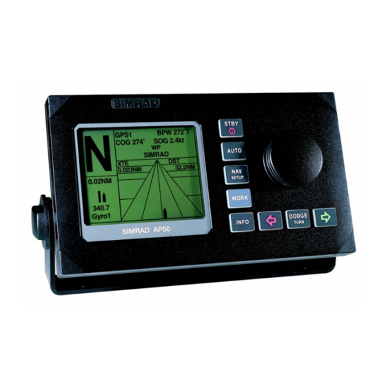
Page 105: Ap50 Control Unit
Type: ..................Backlit LCD matrix Resolution:..................160 x 128 pixels Illumination: ..................Adjustable in 10 grades Mounting: ............Panel mount or bracket mount (optional) Cable:..........Robnet cable 15 m (49 ft.) with one male connector Figure 6-1 AP50 Control Unit Dimensions 20222469 / B... -
Page 106: Ap51 Remote Control
Technical Specifications 6.3 AP51 Remote Control Dimensions: ....................See Figure 6-2 Weight: ....................0.57 kg (1.25 lbs.) Material:.........................PC-ABS Supply............... 12-32 VDC –10%/+30% via Robnet Power consumption ......................3 W Environmental Protection:................... IP56 Safe distance to compass: ................0.35 m (1.0 ft.) Color: ......................... -
Page 107: Junction Units
FU/NFU control input ....................Yes NMEA input/output ports:................... Two External Alarm: ........... Open collector 0.75A (automatic fused) Mounting: ....................Bulkhead-mount System selector Autopilot/Main steering system ......Potential free contact Heading output: .. Simrad and Furuno radar display (clock/data; 0-5V, 10mA, 50 msec.) 20222469 / B... -
Page 108: Rc25 Rate Compass
Technical Specifications Figure 6-3 J50 Junction Unit - Dimensions Figure 6-4 J50-40 Junction Unit Dimensions 6.5 RC25 Rate Compass Dimensions: ....................See Figure 6-5 Weight: ...................... 0.9 kg (2.0 lbs.) Power consumption: ..................... 0.9 watts Supply and interface: ....................Robnet Environmental Protection:................... -
Page 109: Cdi35 Course Detector Interface
Simrad AP50 Autopilot Mounting: ................ Deck-mount or bulkhead-mount Cable:............... 15 m (49 ft.) Robnet cable with connector Automatic Performance: Calibration: ..........Automatically activated by control head Rate sensor stabilized heading output Accuracy:..............<1.25° rms (after calibration) Repeatability: ...................<0.2° rms Roll/Pitch: .......................± 35°... -
Page 110: Cd100A Course Detector
Technical Specifications Cable:..............15 m (49 ft.) single twisted pair, shielded Automatic Performance: Calibration: ..........Automatically activated by control head Repeatability: ....................± 0.5° Accuracy:..± 1,0° after calibration (not including errors from course detector) 6.7 CD100A Course Detector Dimensions: ....................See Figure 6-6 Weight: ................0.3 kg (0.7 lbs.) including cable Environmental Protection:................... -
Page 111: Rf300 Rudder Feedback Unit
Simrad AP50 Autopilot 6.9 RF300 Rudder Feedback Unit Dimensions: ................ See Figure 6-7 and Figure 2-2 Weight: ...................... 0.5 kg (1.1 lbs.) Material: .....................Arnite T06 200 PBT Environmental Protection:................... IP56 Temperature range: Operation: ............... –25 to +55°C (–13 to +130°F) Storage: .............. -
Page 112: Rf45X Rudder Feedback Unit
Technical Specifications 6.10 RF45X Rudder Feedback Unit Dimensions: ............See Figure 6-8, Figure 6-10 and Figure 2-4 Weight: ...................... 1,0 kg (2,2 lbs.) Material: ....................Polyacetal (POM) Supply voltage: ..........12-24 VDC –10%/+30%, system supplied Environmental Protection:................... IP56 Temperature range: Operation: ............... –25 to +55°C (–13 to +130°F) Storage: .............. - Page 113 Simrad AP50 Autopilot Voltage output: ................Operating voltage/2 ±9V Frequency output: ..............3400Hz (midships reference) Port: +20Hz/degree, Stbd: –20Hz/degree Capacity: ..................5 indicators in parallel Rudder angle: ............±45 ° (Changeable to 60, 70 or 90°) Limit switches: ........Two sets, individual adjustable from ±5 to ±160°...
-
Page 114: Ni300X Nmea Interface
Mounting: ....................Bulkhead mount Cable inlets: ..........Rubber glands for cable diameter 10-14 mm NMEA183 input/output:..........4 ports, max. output load 20 mA Heading output: ..Simrad (Anritsu) and Furuno radar display (clock/data; 0-5V, 10mA, 50 msec.) NMEA instrument supply:..............12 VDC, max 0.25A External alarm: ..................Potential free contact... -
Page 115: Ti51 Thruster Interface
Simrad AP50 Autopilot 6.13 TI51 Thruster Interface Dimensions: ....................See Figure 6-11 Weight: ....................... 0,8 kg (1.8 lbs) Material:..................Epoxy coated aluminium Environmental Protection: ..................IP44 Supply and interface: .................Robnet, 2 connectors Cable inlets: ............Rubber glands for cable diam. 10-14 mm Mounting: .................... -
Page 116: R3000X Remote Control
Safe distance to compass:....0.15 m (0.5 ft.) STBY AUTO Temperature range: Operating: ...–25 to +55°C (–13 to +130°F) Storage:....–30 to +70°C (–22 to +158°F) Cable:........7 m (23 ft.), shielded SIMRAD R3000X Mounting bracket: ........Supplied Figure 6-12 R3000X Remote Dimensions 20222469 / B... -
Page 117: S9 Steering Lever
Simrad AP50 Autopilot 6.16 S9 Steering Lever Dimensions: ....................See Figure 6-13 Weight: ....................... 2.8 kg (6.2 lbs) Environmental Protection:................... IP56 Temperature range: Operation: ..........–25 - +55°C (–13 to +130°F) Storage:........... –30 to +70°C (–22 to +158°F) Safe distance to compass: ................0.15 m (0.5’) Max. -
Page 118: Environmental Protection
Technical Specifications 6.17 Environmental Protection Each part of a Simrad autopilot system has a two-digit IP protection code. The IP rating is a method to classify the degree of protection against solid objects, water ingress, and impact afforded by electrical equipment and enclosures. The system is recognized in most European countries and is set out in a number of British and European standards. - Page 119 Missing data AP50 system, NMEA 183 messages (applies for J50 and NI300X sw release V1R2 onwards) timeout (s) Sentence Formatter mnemonic code Bold = recommended navigator/instr. output for autopilot Remarks: Italic = IMO designated ( ) = not for new designs Data source: (A=autop., C=comp., I=instr.
-
Page 120: Index
Index 7 INDEX Course detector Actual rudder, 78 Installation, 43 Added stop time, 84 Specifications, 101 Adjust rudder angle, 68 Course detector interface Alarm Installation, 44 external, 19 Specifications, 100 Analog Heading Repeater, Cruising speed, 67, 82 Analog rudder, 51, 68 Digital Heading Repeater, Analog thruster, 64, 65 AUTO/STANDBY... - Page 121 Simrad AP50 Autopilot NMEA data, 76 IMO MSC(64)67, 95 NMEA input/output Init NAV, 85 Double, 39 Input voltage, 75 Single, 39 Installation NMEA interface Index, 3 installation, 42 Menu, 46 NMEA PORT test, 77 Set-up, 45 NMEA sentences, 109 Interface Menu, 56...
- Page 122 Index Robnet, 17, 26, 93 System select, 18 ROT, 84 System Select, 47 Rudder, 69, 75, 82 rudder angle scaling, 13 Thrust direction, 64 Rudder cal, 51 Thruster calibration, 64 Rudder calibration, 51 Thruster drive, 88 Rudder deadband, 54, 84 Thruster gain, 86 rudder feedback Thruster hyst, 87...
- Page 123 Simrad AP50 Autopilot Work Turn Gain, 85 20222469 / B...
-
Page 124: Approvals
When the equipment is tested according to the requirements in the Directive 89/336/EEC, the CE marking is applied to the units to symbolize Simrad’s Declaration of Conformity with the directive. The CE declaration for any CE marked unit can be obtained from your Simrad distributor. -
Page 125: Certificates
EU’s official database (MarED Product Database) contains information about wheelmarked equipment. This database is found on: http://www.mared.org/ 8.2 Certificates The certificates and CE declarations for any wheel marked equipment can be obtained from your Simrad distributor. 20222469 / B... - Page 126 Simrad doc.no.519103/F...
- Page 127 Simrad doc.no.519103/F...
- Page 128 Simrad doc.no.519107F...
- Page 129 Simrad doc.no.519107F...
- Page 130 Simrad doc.no.519107F...
- Page 131 Simrad doc.no.519107F...
Need help?
Do you have a question about the AP50 and is the answer not in the manual?
Questions and answers
Apabila Autopilot di On otomatis alarm dan menunjukkan Rudder Feedback Failure. Terima kasih
A Rudder Feedback Failure alarm when the Simrad AP50 autopilot is turned on means the feedback unit is operating outside its active segment. This can happen if the mechanical alignment is incorrect and the rudder is not at zero degrees when amidships.
This answer is automatically generated