Table of Contents
Advertisement
Quick Links
Advertisement
Table of Contents

Related Manuals for Simrad AP27


Summary of Contents for Simrad AP27
- Page 1 MANUAL Simrad AP26 and AP27 Autopilots...
- Page 2 This page is intentionally left blank...
- Page 3 Instruction Manual This manual is intended as a reference guide for operating and correctly installing the AP26 and AP27 autopilots. Great care has been paid to simplify operation and set-up of the autopilots, however, an autopilot is a complex electronic system. It is affected by sea conditions, speed of the vessel, hull shape and size.
- Page 4 Simrad AP26 and AP27 Autopilots Document revisions Date Written by Checked by Approved by 18.03.04 27.04.04 Document history Rev. A First edition. Rev. B FU50 substituted by FU25. Part no. for AC40 Power PCB ass’y, page 124 corrected. Added notes in chapter 3.19. Minor corrections in text and display pictures.
-
Page 5: Table Of Contents
2.2 ON/OFF - Standby mode ..............17 Flashing course knob icon ..............18 Alarms ....................18 2.3 AP26 and AP27 with MSD50 Stern Drive unit........18 Zero point setting ................18 2.4 Follow-Up steering (FU)..............19 2.5 Non-Follow-Up steering (NFU) ............20 2.6 R3000X Remote Control (NFU)............ - Page 6 2.11 U-Turn....................25 2.12 Dodge in AUTO.................. 26 2.13 Tacking in Auto mode ................ 27 2.14 Navigating with the AP26 and AP27..........27 Setting the waypoint arrival circle ............30 2.15 Dodge in NAV ..................31 2.16 Selecting a different Navigation source..........31 2.17 Wind vane steering................
- Page 7 Alternative panel mounting of AP26 ..........62 Optional bracket mounting ..............63 3.12 ROBNET2 network cables ..............63 AP27 connection ................. 65 3.13 RC36 Rate Compass installation ............65 3.14 RFC35 Fluxgate Compass installation ..........67 3.15 R3000X Remote Control installation ..........68 3.16 JS10 Joystick..................
- Page 8 Simrad AP26 and AP27 Autopilots SimNet network cables ............... 70 SimNet power and termination ............70 3.20 Single NMEA input/output ..............75 3.21 Double NMEA input/output ............... 75 3.22 NMEA output on Port 2..............76 3.23 NMEA Compass input................ 76 3.24 Radar Clock/Data................
- Page 9 Instruction manual Set Rudder zero................... 97 Minimum rudder ................. 97 Compass calibration................98 Compass Offset ................. 100 Wind Offset..................101 Wind damping................... 101 Depth Offset..................102 Automatic tuning................102 Transition Speed ................103 Init NAV ................... 104 4.8 Parameters ..................104 Manual parameter adjust..............
- Page 10 Trouble shooting ..................118 6.1 Alarms ....................118 Spare Parts List..................123 Technical Specifications ................126 8.1 AP26 and AP27 Autopilot System ........... 126 8.2 AP26 Control Unit ................127 8.3 AP27 Control Unit ................129 8.4 Autopilot Computers................. 130 8.5 RC36 Rate compass ................
-
Page 11: System Description
In the AP26 and AP27 autopilots Simrad introduces the new SimNet data and control network. SimNet provides high speed data transfer and control between Simrad products that are integrated as a total steering and navigation system onboard. -
Page 12: System Components
System components A basic autopilot system consists of the following units (refer to Figure 1-1): • AP26 Control Unit or AP27 Control Unit with accessories • Autopilot Computer • Rate compass • Rudder Feedback Unit with transmission link •... -
Page 13: Ap26 Control Unit
It has two Robnet2 connectors for system interconnection and expansion and two SimNet connectors for control and data sharing with other Simrad products. A NMEA2000 Adapter Cable is available for interface through a SimNet port (page 125). AP27 Control Unit A portable control unit with 7 m (20 ft.) of cable. -
Page 14: Rf300 Rudder Feedback Unit
Transforms the angular travel of the rudder to a digital signal read by the autopilot steering computer. Heading Sensors The AP26 and AP27 autopilots can be used with the following combinations of heading sensors: RC36 Rate compass Fluxgate compass with integrated rate sensor. Provides a dramatic improvement to the dynamic performance of both the autopilot and a stabilized radar display. -
Page 15: Nmea Compass (Optional)
AC40 autopilot computer. It is absolutely necessary for the autopilot that the heading rate is minimum 10 Hz. Simrad RGC10 and RGC50 gyrocompasses The optional GI51 unit is needed to interface these two gyrocompass models. Ask your Simrad dealer for information. 20221586B... -
Page 16: Optional Equipment
Simrad AP26 and AP27 Autopilots Optional equipment A series of optional equipment are available for the basic AP26 and AP27 systems. R3000X Remote Control A small handheld remote control with two push buttons for power steering or course selection (port and starboard), and one push button with built-in lighted indicator for limited mode change. -
Page 17: Operation
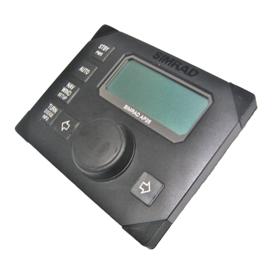
Installation 2 OPERATION WARNING ! An autopilot is a very useful navigational aid, but DOES NOT under any circumstance replace a human navigator. Do not use automatic steering when: • In heavy traffic areas or in narrow waters • In poor visibility or extreme sea conditions •... - Page 18 Simrad AP26 and AP27 Autopilots STBY AUTO WIND DODGE SETUP INFO Figure 2-2 AP27 Front Panel The control units shown above can operate as a stand alone unit in an autopilot system or combined in a multistation system. In a multistation system the command can easily be transferred from one unit to another.
-
Page 19: On/Off - Standby Mode
ON/OFF - Standby mode At first time turn on see paragraph 4.1. Note ! A single press on the STBY button switches the system ON and the following status displays are shown: Simrad Autopilot model AP26 SW 1.0.00 Software version Software release HW rev. -
Page 20: Flashing Course Knob Icon
In the event there is an audible alarm with explaining text on the control unit, refer to section 6 Trouble shooting. AP26 and AP27 with MSD50 Stern Drive unit The information in section 2.3 only applies if your autopilot is Note ! driving a Simrad MSD50 Stern Drive. -
Page 21: Follow-Up Steering (Fu)
Installation Use the wheel to bring the "rudder" to midship position. Turn the wheel from lock to lock (H.O. to H.O.) and count the exact number of turns. Then start from one lock position and turn the half number of turns. Press AUTO and then STBY. -
Page 22: Non-Follow-Up Steering (Nfu)
Simrad AP26 and AP27 Autopilots Non-Follow-Up steering (NFU) In Standby mode, the NFU display is presented when the PORT or STBD button is pressed. The rudder will move as long as the button is pressed and the rudder angle is shown on the display. -
Page 23: R3000X Remote Control (Nfu)
If you keep the button pressed, it will are active when automatically change the setting in the lamp is lit. increments of 3° per second. Mode changes are as per table below. Simrad R3000X Initial mode press 2 press STBY AUTO... -
Page 24: Automatic Steering
Simrad AP26 and AP27 Autopilots Automatic Steering When AUTO mode is selected, the autopilot automatically picks the current boat heading as the set course and maintains the simultaneous rudder angle. This gives a bumpless transfer at the mode change. The main Auto mode display shows the mode index and the set course. -
Page 25: Automatic Control Of Steering Parameters
Installation button. The autopilot will immediately counteract the turn and the boat will continue straight ahead on the heading read from the compass the very moment you pressed the AUTO button. Automatic steering mode New “caught” heading: 305° Compass reading: 303° M (magnetic) or T (true) Rudder angle: 00°. -
Page 26: Sailboat
Simrad AP26 and AP27 Autopilots Speed Transition to LO parameters with increasing speed: 10 Knots Transition Speed set to 9 Knots Transition to HI parameters with decreasing speed: 8 Knots Sailboat When sailing in WIND mode, the parameters are automatically changed by the direction of the wind as per below or by the boat speed. -
Page 27: U-Turn
Installation To toggle between LO and HI parameters, press the "AUTO" button two times quickly. Quick double press Notes ! 1. If you are in NAV or WIND modes you need not enter AUTO mode to manually change the parameter set. Just make a quick double press on the AUTO button. -
Page 28: Dodge In Auto
Simrad AP26 and AP27 Autopilots 2.12 Dodge in AUTO Dodging is useful in situations where you need to quickly take control of the helm to steer around an obstruction, and then resume the previous set heading. Dodging is activated by a quick double press on the TURN/DODGE/INFO button. -
Page 29: Tacking In Auto Mode
STBD tack 2.14 Navigating with the AP26 and AP27 The autopilot has the capability to use steering information from an external navigator (GPS, Chart Plotter) to direct the boat to a specific waypoint location, or through a route of waypoints. In the NAV mode, the autopilot uses the compass as heading source for course keeping. - Page 30 Simrad AP26 and AP27 Autopilots • The autopilot autosteering must be tested and determined satisfactory. • The navigation receiver (GPS, Chart Plotter) must be in full operating mode with adequate signal characteristics for valid position and navigation data. • At least one waypoint must be entered and selected as the current “Go to”...
- Page 31 Installation − NAV mode − Course to steer (CTS): 260 is set internally by the autopilot to steer the boat onto the track line. − Cross track error (XTE): 0.010 nm to stbd. For Cross Track Error, the number of decimals shown depends Note ! on the output from the GPS/chart plotter.
-
Page 32: Setting The Waypoint Arrival Circle
Simrad AP26 and AP27 Autopilots Regain manual steering by pressing the STBY button Setting the waypoint arrival circle For route navigation it is recommended to use automatic waypoint shift/change at a set waypoint arrival circle. The arrival circle should be adjusted according to boat speed. -
Page 33: Dodge In Nav
Installation 2.15 Dodge in NAV When dodging in NAV mode, the course displayed as Course To Steer (CTS) is the boat’s recommended heading. However, the previous set course is stored by the autopilot. When DODGE is flashing on the display, the autopilot is no longer in control of the steering and you must either steer the boat manually or take control using either Non-Follow-up steering or Follow-up steering. -
Page 34: Wind Vane Steering
Simrad AP26 and AP27 Autopilots 2.17 Wind vane steering Prior to entering WIND mode the autopilot system should be operating in AUTO, with valid input from the selected wind transducer. The WIND mode is only available if the system has... -
Page 35: Tacking And Gybing In Wind Mode
Installation Regain manual steering by pressing the STBY button 2.18 Tacking and gybing in Wind mode In WIND mode there is a tacking and gibing aid function. Tacking in WIND mode as compared to AUTO mode can be performed when sailing with apparent or true wind as the reference, and with a true wind angle of less than 90 degrees. -
Page 36: Gybing
Simrad AP26 and AP27 Autopilots Gybing Gybing is possible when the true wind angle is larger than 120° When a gybe is initiated, the wind angle will first be set to 170°T on the same side as the current wind angle. The main sail should now be hauled. -
Page 37: Wind Steering And Navigation
Installation The gybe prevent function will be activated when the measured apparent wind angle becomes greater than 175° or when the wind angle gets opposite to the set wind angle. Additional rudder will be commanded to keep the wind on the same side as the set wind angle. - Page 38 Simrad AP26 and AP27 Autopilots [2] [4] [3] [7] Figure 2-3 20221586B...
-
Page 39: Operating In Wind Nav Mode
Installation Operating in WIND mode Refer to Figure 2-3 with references [ ] the associated displays and the criteria (bullets) below. • The set wind angle should be larger than the ‘Minimum wind angle’ set in the Installation/Dockside menu and smaller than 170°... -
Page 40: Multiple Station System
Simrad AP26 and AP27 Autopilots 2.20 Multiple station system In normal operation control is accessible from every control unit connected to the autopilot system. One control unit is "active" and provides the user with access to all functions. All remaining control units are "inactive"... -
Page 41: User Set-Up Menu
Installation 2.22 User Set-up Menu In the AP26 and AP27, all modes except NFU and FU have a complemental User Set-up menu. You can easily access the set- up menu by a quick double press on the NAV/WIND/SETUP button. Use the course knob to... - Page 42 Simrad AP26 and AP27 Autopilots Nav/Wind This parameter will only be available if ‘Boat type’ is set to ‘Sail’ in the Installation/Dockside menu (see Dockside settings, page 88). The ‘Nav/Wind’ parameter will configure the active mode on the NAV/WIND button.
- Page 43 Installation ‘WIND Apparent’ is selected when you only want to steer to apparent wind. Apparent wind steering is preferred when you want to achieve maximum boat speed. The autopilot will try to maintain a constant apparent wind angle to get maximum thrust from a given trim of the sails.
- Page 44 (Compass), Navigation, Position, Wind Angle, Calculated Wind, Water speed, Water temperature, Distance log (not displayed on AP26 and AP27) and Depth. Wind-C (calculated) is a common term for true wind and wind direction. Auto source update...
- Page 45 Installation Notes ! 1. Simrad products will be identified by the product name provided the data is available on SimNet. If data is provided via an NMEA0183 port on the autopilot computer, the display will read NMEA-1 or NMEA-2. NMEA2000 products will have a special ID.
-
Page 46: Auto Mode
Simrad AP26 and AP27 Autopilots DisLog Select the Log source. Depth Select the source for depth data. Course Adjust When using the (PORT) or (STBD) buttons in AUTO mode, you are changing the set course in 1° increments. If you prefer the increments to be 10°... -
Page 47: Nav Mode
Installation Response The Autotune function in the AP26 and AP27 is so refined that 80-85 % of the boats will need no further adjustments of the steering parameters. On some boats, however, or at particular sea conditions a fine tuning of the steering parameters may improve the performance of the autopilot. -
Page 48: Info Menu
Simrad AP26 and AP27 Autopilots If the actual wind angle is S-ing around the set wind angle or the rudder activity is too high, the ‘Wind response’ should be reduced. Range: 1 – 7 Default: 3 See also other relevant settings for WIND mode operation under STANDBY mode in this chapter. - Page 49 Installation Nav mode For Nav mode the alternative mode screen gives you the name of the waypoint, bearing and distance to waypoint and rudder angle. This screen is also among the INFO pages. Step or scroll through the available instrument screens by pressing the PORT or STBD button or using the course knob.
-
Page 50: Course Knob Icon
Simrad AP26 and AP27 Autopilots Track data Cross Track Error Distance to Waypoint Position Latitude Longitude Nav data Waypoint ID Bearing Position – Waypoint Nav data Course Over Ground Speed over ground Nav data Course Over Ground Bearing Position – Waypoint... -
Page 51: Info Menu Flowchart
Installation INFO menu flowchart Long DODGE press INFO 3-5 sec. time-out Long Toggle DODGE DODGE press INFO INFO 3-5 sec. time-out 20221586B... -
Page 52: Alternative Mode Screens In Stby, Auto And Nav
Simrad AP26 and AP27 Autopilots Alternative mode screens in STBY, AUTO and NAV Main (STBY, AUTO, NAV) Alternative Long press DODGE INFO 3-5 sec. time out 3-5 sec. Toggle time out DODGE INFO Long press Long press DODGE INFO INFO menu and Main screen, active unit 3-5 sec. -
Page 53: Installation
Installation 3 INSTALLATION General This section provides detailed information required to successfully installing the AP26 andAP27 Autopilot system. The autopilot systems include several modules that need to be mounted in different locations on the boat, and also need to interface with at least three different systems on the boat: •... -
Page 54: Unpacking And Handling
Simrad AP26 and AP27 Autopilots c) Compass Offset adjustment d) Automatic tuning e) Viewing parameters 9. Test Autopilot Operation at Sea (refer to Sea Trial instructions, pages 96, 112) 10. Provide the user with training (Page 113) Unpacking and handling Care should be taken when unpacking and handling the equipment. -
Page 55: Autopilot System Layout
Installation Autopilot System Layout STBY STBY STBY AUTO AUTO AUTO WIND WIND SETUP SETUP DODGE DODGE INFO INFO pfjo^a=oPMMMu STBY AUTO SPEED SETUP TURN Figure 3-1 Autopilot system layout with options RF300 Rudder feedback installation The RF300 Rudder feedback unit mounts close to the rudder, and is mechanically linked to the rudder tiller arm or rudder quadrant. - Page 56 Simrad AP26 and AP27 Autopilots Attach the ball joint to the tiller arm, and connect the transmitter rod to the ball joint at the rudder tiller arm. Turn the helm wheel to set the rudder tiller arm to approximate centre position.
-
Page 57: Autopilot Computer Installation
Installation AUTOPILOT COMPUTER MAIN PCB Rudder Feedb. * NON POLARIZED (COLOR INDEPENDENT) Figure 3-3 RF300 connection Autopilot computer installation The autopilot computer is designed to operate in a location that provides ambient temperatures below +55°C (+130°F). The autopilot computer Note ! units (AC10, AC20 and AC40) weatherproof and should... -
Page 58: Grounding And Rfi
Simrad AP26 and AP27 Autopilots Refer to the table below for recommended cable sizes. Cable length Drive Unit Voltage 1. Breaker panel to autopilot computer. 12 V 24 V 2. Autopilot computer to Drive Unit motor (Length refers to each of the two cables) Up to 3 m (10 ft.) - Page 59 Installation Note! Ground terminal The Mains input is not polarity protected on AC40. Power Board terminals TB9 and TB10 are not on the AC10 Power Board Main Board terminals 20221586B...
-
Page 60: Drive Unit Installation
Simrad AP26 and AP27 Autopilots 3.10 Drive unit installation The relations between drive units, drive unit voltage, autopilot computer, drive performance and interface to the steering gear are shown in the tables below. Refer to the connecting diagram for the different drive units on page 60 onwards. - Page 61 Installation LINEAR DRIVE UNITS MODEL MOTOR AUTO- PEAK HARD- PWR. TILLER VOLTS PILOT STROKE THRUST RUDDER OVER CON- COM- mm (in.) kg (lb.) TORQUE TIME SUMP. PUTER sec. (in.) (lb.in.) (30% load) MLD200 AC10 300 (11,8) 1,5-6 A (440) (4350) (10,4) HLD350 AC10...
-
Page 62: Connecting A Reversible Pump
Simrad AP26 and AP27 Autopilots PREVIOUS MODELS OF DRIVE UNITS Model Autopilot Drive unit Input Drive output Interface to computer voltage voltage steering (Mains) gear RPU100 (1,0l) AC20 12,24,32V Proportional Hydraulic RPU150 (1,5l) AC20 rate plumbing RPU200 (2,0l) AC20 (Reversible... -
Page 63: Connecting A Hydraulic Linear Drive
Installation Connecting a hydraulic linear drive HYDRAULIC AUTOPILOT COMPUTER LINEAR DRIVE POWER PCB TB1 TB2 TB3 TB4 TB5 Bypass Clutch Single pole clutch/bypass switch Figure 3-6 Connecting a hydraulic linear drive Connecting a solenoid valve AUTOPILOT COMPUTER SOLENOID POWER PCB VALVE TB1 TB2 TB3 TB4 TB5 Sol. -
Page 64: Control Unit Installation
This way of mounting is simpler, but will lift the unit from the panel surface. When installed adjacent to Simrad equipment there will be a difference in height between the autopilot and the other equipment. • Use the template and drill hole(s) only for the connectors. -
Page 65: Optional Bracket Mounting
Installation Optional bracket mounting • Locate the cradle on the mounting site and mark the 4 holes for the fixing screws on the mounting surface. • Drill the 4 mounting holes and screw the cradle to the mounting surface. • Use the supplied screws to fasten the control unit to the left and right brackets. - Page 66 Simrad AP26 and AP27 Autopilots both ends are available in 1, 5 and 10 m length. For cable extension a Robnet2 T-Joiner is required. When installing a system, try to minimize the total cable length by connecting all Robnet2 units to the nearest available Robnet2 connector.
-
Page 67: Ap27 Connection
J1 and J2 (left) are Robnet2 connectors. J3 and J4 are SimNet connectors. AP27 connection If a Simrad AP27 is part of the system, use the Robnet2 connector in a free receptacle (see Figure 3-9). Alternatively cut the connector from the cable and connect the wires in parallel with the cable shown on Figure 3-11 using the same colour code. - Page 68 Simrad AP26 and AP27 Autopilots mounting location. As the heading is displayed on the Control Unit, the heading sensor can be mounted at a remote location. The RC36 rate compass also contains a magnetic heading sensor, so particular attention must be paid to the location. It can be mounted on deck or bulkhead, athwartship or alongship and has a 15 m (99’) cable with a Robnet2 connector.
-
Page 69: Rfc35 Fluxgate Compass Installation
Installation RATE COMPASS AP16, AP25, AP26 Figure 3-13 RC36 connection to autopilot control unit Plug the RC36 into a Robnet2 connector (see Figure 3-9) or cut the connector from the cable and connect the wires in parallel with the cable shown in Figure 3-11. 3.14 RFC35 Fluxgate Compass installation (Optional back-up) The RFC35 Fluxgate Compass is a magnetic sensor, which... -
Page 70: R3000X Remote Control Installation
Simrad AP26 and AP27 Autopilots 3.15 R3000X Remote Control installation R3000X should be mounted in the supplied bracket that can be fixed by four mounting screws. The unit is weather proof and can be mounted outdoor. R3000X AUTOPILOT COMPUTER REMOTE CONTROL... -
Page 71: Interfacing
3. Connect to a NMEA2000 network or unit 4. The AC10 has a single NMEA0183 input/output port. 5. The AC20 and AC40 have two NMEA0183 input/output ports and Clock Data interface to Simrad and Furuno radars. The NMEA0183 output may also drive Simrad IS15 instruments directly. -
Page 72: Simnet Network Cables
Simrad AP26 and AP27 Autopilots SimNet network cables A SimNet unit has one or two yellow SimNet connectors. There are no dedicated “in” or “out” connectors. Find the shortest and easiest way to route the SimNet cables from product to product and select the standard length cables from the SimNet accessory program. - Page 73 Installation `lj_f `lj_f a^q^ pfjo^a=fpNO pfjo^a=fpNO pfjo^a=fpNO STBY AUTO ^i^oj rmmbo iltbo ^i^oj rmmbo iltbo rmmbo iltbo ifdeq ifdeq ifdeq m^db INFO qfjbo fkcl fkcl qfjbo fkcl fkcl fkcl fkcl TURN WIND SETUP DODGE Figure 3-17 SimNet network, small system a^q^ `lj_f `lj_f...
- Page 74 Simrad AP26 and AP27 Autopilots `lj_f `lj_f `lj_f a^q^ pfjo^a=fpNO pfjo^a=fpNO pfjo^a=fpNO pfjo^a=fpNO ^i^oj rmmbo iltbo ^i^oj rmmbo iltbo ^i^oj rmmbo iltbo ifdeq m^db rmmbo iltbo ifdeq ifdeq ifdeq qfjbo fkcl fkcl qfjbo fkcl fkcl qfjbo fkcl fkcl fkcl fkcl...
- Page 75 Installation `lj_f `lj_f a^q^ pfjo^a=fpNO pfjo^a=fpNO pfjo^a=fpNO STBY AUTO INFO ^i^oj rmmbo iltbo ^i^oj rmmbo iltbo ifdeq m^db rmmbo iltbo ifdeq ifdeq fkcl fkcl TURN qfjbo fkcl fkcl qfjbo fkcl fkcl WIND SETUP DODGE Figure 3-20 Robnet2 and SimNet network 20221586B...
- Page 76 Simrad AP26 and AP27 Autopilots STBY STBY AUTO AUTO WIND WIND DODGE DODGE INFO SETUP Figure 3-21 Robnet2, SimNet and Roblink network Notes ! 1. Maximum total length of SimNet cable is 40 m (130 ft.) excluding the 30 m (99 ft.) of masthead cable.
-
Page 77: Single Nmea Input/Output
Installation 3.20 Single NMEA input/output NAV RECEIVER AUTOPILOT COMPUTER OR PLOTTER MAIN PCB (NMEA talker) TB13 TB14 NMEA listener NMEA NMEA Output1 Input 1 Note IS15 RUDDER IS15 COMPASS RADAR Figure 3-22 Single NMEA connection If an IS15 Instrument is powered from TB14 Vbat+ and Gnd, Caution ! please observe that Vbat output voltage will follow mains supply voltage (IS15 Compass = 12V only!). -
Page 78: Nmea Output On Port 2
Simrad AP26 and AP27 Autopilots 3.22 NMEA output on Port 2 Output signal Output terminal Output sentence Continuous output of compass Autopilot Computer Power HDT (True) or HDG (Magn.) heading at 10 Hz (10x/sec.) PCB. depending on heading source. Rudder angle output at 5 Hz NMEA2, TX2+, TX2–... -
Page 79: Radar Clock/Data
Installation 3.24 Radar Clock/Data SIMRAD/ AC20/AC40 AUTOPILOT COMPUTER ANRITSU P O W E R P C B FURUNO T B 1 0 T B 8 T B 9 RADAR R a d a r Figure 3-25 Radar Clock/Data connection 3.25 IS15 Instrument installation For installation and operation of the IS15 instruments refer to separate manuals. - Page 80 Simrad AP26 and AP27 Autopilots If IS15 Expander is used in the instrument system, the NMEA connections are made to this unit. See Figure 3-27. Figure 3-26 IS15 Instruments / Autopilot computer connection Figure 3-27 IS15 Expander / Autopilot computer connection...
-
Page 81: External Alarm
Installation 3.26 External Alarm The external alarm circuit has an open collector output for an external alarm relay or buzzer. The operating voltage for the circuit is the main supply voltage. Max. load on external alarm output is 0.9 Amp. AUTOPILOT COMPUTER POWER PCB Ext. - Page 82 Simrad AP26 and AP27 Autopilots the bolt. Secure the feedback rod to the retainer plate using the two washers and the cap nut provided. Adjust the location of the LF3000 Linear Feedback to allow full travel of the hydraulic cylinder without causing the retainer plate to hit the end of the cylinder.
- Page 83 Installation Electrical connection AUTOPILOT COMPUTER LFI3000 Mk2 LINEAR FEEDBACK MAIN PCB INTERFACE Rudder Feedb. Figure 3-30 LF3000/LFI3000 Mk2 connections 20221586B...
- Page 84 Simrad AP26 and AP27 Autopilots This page is intentionally left blank. 20221586B...
-
Page 85: Configuration And Setup
Maintenance 4 CONFIGURATION AND SETUP First time turn on Before attempting to turn on the autopilot and perform an Installation Setup, the hardware installation and electrical connections must be completed in accordance with the installation instructions. The design of the autopilot includes advanced features that have simplified the installation and setup of an autopilot. -
Page 86: Description Of Installation Settings
Simrad AP26 and AP27 Autopilots Description of Installation Settings The installation settings must be performed as part of the Note ! installation of the autopilot system. Failure to do so correctly may prohibit the autopilot from functioning properly! The Installation menu can only be accessed in STBY mode. -
Page 87: Installation Menu
Maintenance • The Installation Settings are global except for display units and language, enabling settings to be distributed to all control units in the system. • The Seatrial settings are dependent on successful completion of the Dockside settings. Installation Menu Installation Menu presented... - Page 88 Simrad AP26 and AP27 Autopilots ENTER INSTALLATION MENU INSTALLATION SYMBOLS BY PRESSING AND HOLDING THE MENU NAV BUTTON FOR 5 SECONDS SELECT OR CONFIRM BY COURSE KNOB LANGUAGE MENU PROCEED TO NEXT MENU ITEM LANGUAGE ENGLISH BY PRESSING STBD BUTTON...
-
Page 89: Language Selection
Maintenance Language selection To access the language selection in the Installation Menu, confirm “Yes” by turning the course knob clockwise The autopilot can present the display text in eight different languages: English, Deutsch, Francais, Espanol, Italiano, Nederlands, Svenska and Norsk. Turn the course knob to select the language you wish to use. -
Page 90: Boat Type
Simrad AP26 and AP27 Autopilots Select STANDBY mode and enter the Installation Menu as previously described. Select Dockside by pressing STBD button and confirm by rotating the course knob clockwise. Boat type Actual boat type is selected by turning the rotary course knob. -
Page 91: Rudder Feedback Calibration
Maintenance Rudder Feedback Calibration Make sure the RF300 is installed and aligned as pr. instruction in section 3.6 (or eventually section 3.27 for LF3000). This function enables you to compensate for any non-linearity in the transmission between the rudder and the rudder feedback. Confirm Rudder feedback calibration to STBD by turning the course knob... -
Page 92: Rudder Test
Simrad AP26 and AP27 Autopilots Rudder Test If the boat uses power assisted steering, it is important that the Note ! engine or electric motor used to enable the power assist steering be turned on prior to this test. Bring the rudder manually to midship position before starting the test. -
Page 93: Drive Engage
Maintenance Test of LF3000/LFI3000 Mk2 feedback 1. Align engines to centre position; “zero rudder”. 2. Rev engines to 3-4000 rev/min and observe the rudder angle indicator on the autopilot, a 2° change in the reading should be accepted. 3. If the rudder angle exceeds 2°, connect the screen on the TB1 cable to the centre block terminal and repeat item 2 (See Figure 3-30). -
Page 94: Rudder Deadband
Simrad AP26 and AP27 Autopilots Rudder Deadband The rudder deadband function is adaptive and is continuously operative. prevents rudder from hunting and the adaptive function optimizes the deadband to the speed of the boat and the pressure on the rudder. -
Page 95: Minimum Wind Angle (Normal)
Maintenance Minimum wind angle (NORMAL) The ‘Minimum wind angle’ is the minimum apparent wind angle that will keep the sails well shaped and give an acceptable thrust. This parameter will vary from boat to boat. The ‘Minimum wind angle’ applies in the tack-prevent function. It also applies when the autopilot is navigating in Wind mode. -
Page 96: Tack Time (Racing)
Simrad AP26 and AP27 Autopilots Tack time (RACING) When performing a tack in WIND-mode, the rate of turn can be limited. This will give single handed sailors time to handle the boat and the sails during a tack. The tack time is the time needed for the sailor to initiate the tack, start using the winches and hauling the foresail from one side to the other. -
Page 97: Interface Settings
Maintenance Interface Settings Sets the format of the clock/data output for radars connected to the Autopilot Computer. Step to the Interface part of the Installation Menu. Turn the course knob clockwise to access the Interface Setup items. Use the course knob to select the connected type of radar. -
Page 98: Sea Trial
Simrad AP26 and AP27 Autopilots Sea Trial The Sea Trial must always be performed in open waters at a Caution ! safe distance from other traffic. The Sea-trial menu can only be accessed if the Dockside Settings are completed and confirmed. -
Page 99: Set Rudder Zero
Maintenance Set Rudder zero This adjustment should be made in calm sea and side forces from wind or current should be avoided. • Bring the boat up to cruising speed, and head directly into the wind. • If the boat has twin engines, synchronize the engine RPM's. •... -
Page 100: Compass Calibration
RATE-0 = Rate compass, FLUX-0 = Fluxgate compass on HS terminals. If an optional NMEA compass from Simrad or another manufacturer is installed, also refer to the optional compass’ manual regarding calibration. This compass will not be calibrated by the autopilot. - Page 101 Maintenance 4. When the calibration is completed, (after having made approximately 1 1/4 turns), it will be confirmed by the display reading “Confirmed”. Compass deviation The heading from a magnetic heading sensor will normally have a deviation when compared with the actual direction of the earth’s magnetic field.
-
Page 102: Compass Offset
Simrad AP26 and AP27 Autopilots Compass Offset After calibration, also check the compass readout against a known reference, a compensated compass or a bearing. If the reading has a fixed offset, proceed to next menu item by pressing STBD button or return to STANDBY mode by pressing the STBY button. -
Page 103: Wind Offset
Maintenance Wind Offset This offset only applies if you have a wind transducer directly Note ! connected to SimNet (IS12TW) or a wind transducer that outputs data on NMEA2000 format. The Wind Offset feature allows you to correct for a fixed wind angle offset. -
Page 104: Depth Offset
Simrad AP26 and AP27 Autopilots Depth Offset This adjustment only applies to “smart” depth transducers that Note ! outputs depth on NMEA2000 format. NMEA0183 sentence ‘DPT’ contains offset and the depth reading is from the surface. NMEA0183 sentence ‘DBT’ contains no depth offset and the reading will be from the position of the transducer. -
Page 105: Transition Speed
Maintenance It also is recommended to perform the Automatic tuning steering East or West, as this will yield the best balanced parameters. After the Automatic tuning has been completed the rudder must Note ! be controlled manually, as the autopilot has returned to STBY mode. -
Page 106: Init Nav
Simrad AP26 and AP27 Autopilots Rotate course dial clockwise until the transition speed is set to the desired value in knots. Range: OFF – 30 knots Default: 5 knots Proceed to next menu item by pressing STBD button. Init NAV Sets a firm or soft approach to the track line when entering the NAV mode at the first leg. -
Page 107: Manual Parameter Adjust
Maintenance • HI value parameters for automatic steering at low speed with a power boat and when running with a sailboat. • LO value parameters for automatic steering at high speed and when sailing into the wind or reaching with a sailboat. Step through the menu items by pressing the STBD or PORT buttons. - Page 108 Simrad AP26 and AP27 Autopilots Rudder sets the rudder gain which is the ratio between the commanded angle and the heading error. Course to steer Too little Rudder Course to steer Too much Rudder • Too little Rudder and the autopilot fails to keep a steady course.
-
Page 109: Recall Autotuned
Maintenance New course Correct setting of counter rudder, ideal response Autotrim standard value is 40 sec. which should work well on most boats. Rudder Limit should be kept at 20 degrees unless there is a need for more rudder when performing dockside manoeuvres. Recall Autotuned? To recall the parameter values that were achieved during the... -
Page 110: System Data Menu
Simrad AP26 and AP27 Autopilots System Data Menu Select System data by rotating the course knob clockwise. Step through the menu by pressing the STBD button. The menu provides with additional system data that can be useful when testing or trouble shooting the system. - Page 111 Maintenance Decoding The incoming signals are decoded according to a built in priority table in the autopilot. Cross Track Error and bearing information are taken from the NMEA messages with highest priority. For all data items, one of the following codes will be displayed: –...
-
Page 112: Nmea Port Test (Ac Hardware)
Simrad AP26 and AP27 Autopilots NMEA signal monitor Near the NMEA terminals in the Autopilot Computer you will find a green monitor LED marked “RX”. A flickering LED indicates that a NMEA signal is received. It does not, however, qualify the contents of the message. - Page 113 Indicates which control unit that transmits receives information on SimNet. The display verifies reading ‘Yes’, all other units read ‘No’. Global SimNet reset Resets the entire SimNet setup in the Simrad Group and initiates a new automatic interface setup. See chapter 4.1. 20221586B...
-
Page 114: Master Reset
Simrad AP26 and AP27 Autopilots Master Reset A Master Reset is part of the final test at the factory, which will Note ! reset the memories to factory settings. Unless you need to clear all stored values during the installation setup procedure, you should not perform a Master Reset. -
Page 115: Providing User Training
Maintenance • Try the Dodge and U-turn function. • If a Non-Follow Up lever (or handheld remote) is connected, test change of modes and verify port and starboard steering commands of the lever. • Set waypoints into each navigator connected to the system, and verify that the autopilot steers in NAV mode for each NAV source. - Page 116 Simrad AP26 and AP27 Autopilots • Locating the Mains circuit breaker and the separate SimNet circuit breaker if provided. 20221586B...
-
Page 117: Maintenance
Maintenance 5 MAINTENANCE Control unit The AP26 and AP27 Control Units will under normal use require little maintenance. If the unit requires any form of cleaning, use fresh water and a mild soap solution (not a detergent). It is important to avoid using chemical cleaners and hydrocarbons such as diesel, petrol etc. -
Page 118: Exchange Of Software Programme
Simrad AP26 and AP27 Autopilots Exchange of software programme Autopilot Computer Autopilot Computer EPROM Figure 5-1 AC10/AC20/AC40 Main PC-Board • Remove the EPROM from the socket by means of the special extraction tool (p/n 44139806). • Insert the tool by pressing the two grip pins down into the two slots in the corners of the socket. -
Page 119: Autopilot Control Unit
Maintenance Autopilot Control Unit You will need a special kit for a PC to perform the programming of the Control Unit. Order the following from Simrad: Programming kit P/N 22088595. Instructions are included. Software download connector Figure 5-2 Part of AP26 PCB... -
Page 120: Trouble Shooting
Simrad AP26 and AP27 Autopilots 6 TROUBLE SHOOTING An autopilot is a complex system. Its performance dependents on a proper installation and a successful sea trial. In the event of an autopilot failure, the autopilot’s numerous test features will assist you in isolating a probable fault. - Page 121 Trouble shooting Display readout Probable fault Recommended action Shallow water The depth is inside 1. Carefully observe the actual the set limit or outside depth. (Only if AP25 is the range. part of the 2. Adjust the alarm limit if not system) Depth data is missing.
- Page 122 Simrad AP26 and AP27 Autopilots Display readout Probable fault Recommended action Rudder test failed Following conditions Refer to recommended actions for may exist: the specific probable faults. a) Rudder feedback failure b) Autopilot Computer current overload c) Bypass/clutch overload Rudder moves in only...
- Page 123 Trouble shooting Display readout Probable fault Recommended action Failure active Active control unit 1. Press the STBY button on an Control Unit goes silent. "Inactive" unit to reset. 2. Check/repair Robnet2 cable. 3. Replace the control unit PCB. ACXX current The drive unit shut 1.
- Page 124 Simrad AP26 and AP27 Autopilots Display readout Probable fault Recommended action Com. failure with Faulty Autopilot 1. Check Robnet2 connectors and ACXX Computer or poor cable. Robnet2 cable 2. Replace Autopilot Computer Main connections from PCB. the same. Low supply Mains voltage less 1.
-
Page 125: Spare Parts List
AP26 Back Ass’y 22087761 AP26 Board Ass'y 22084750 Protection Cover 22088181 AP26&AP27 software AP27 Control Unit 22088090 AP27 Control Unit 22086276 AP27 Standard Mounting kit 22087795 AP27 Board Ass'y 22088181 AP26&AP27 software 22086193 Back cover Autopilot Computers 22088108 AC10 Autopilot Computer 22088116... - Page 126 Simrad AP26 and AP27 Autopilots 22081251 AC20 Power PCB Ass'y 22081715 AC10 Power PCB Ass'y 22088694 AC40 Power PCB Ass'y 22088447 AC Main PCB Ass'y (All models) 22088462 PROM for all autopilot computers 22081434 AC10/AC20 Base plate 22082036 AC40 Base plate...
- Page 127 Spare parts list 24005621 Robnet2 cable, 5 m (16’) with two plugs 24005639 Robnet2 cable, 10 m (33’) with two plugs 24005647 Robnet2 cable 15 m (49’) with one plug 24005662 Robnet2 joiner SimNet cables and accessories 24005829 SimNet cable 0.3 m (1’) 24005837 SimNet cable2 m (6.6’) 24005845...
-
Page 128: Technical Specifications
NMEA output sentences:.. BWC, BWW, GLL, HDG, HDM, HDT, HSC, RMB, RMC, RSA, VTG, XTE. See chapter 8.14 for NMEA0183 details. Optional output: ....Simrad and Furuno radar display (clock/data) NMEA2000 interface..Via SimNet port and SimNet/NMEA2000 adapter cable 20221586B... -
Page 129: Ap26 Control Unit
Heading sensors: Standard: ......RC25 Rate Compass Options:......RFC35 Electronic Fluxgate compass NMEA Compass (Not AC10) Simrad RGC50/RGC10 gyrocompasses * * By GI51 Course Selection:....... Rotary course dial and push button Alarms: ........Audible and visual, optional external Alarm modes: ......Off course, system failures, overload Steering modes: ...... - Page 130 Simrad AP26 and AP27 Autopilots Display: Type: ......... Backlit LCD matrix display Resolution: ......80 x 32 pixels Colour: ........Black Illumination: ......Adjustable in 10 steps Environmental Protection:..IP56 from front, IP43 from back. Safe distance to compass: ..0.3 m (1.0 ft.) Temperature: Operating: ......
-
Page 131: Ap27 Control Unit
Operating: ......0 to +55 °C (+32 to +130 °F) Storage: ......–30 to +80 °C (–22 to +176 °F) Mounting: ........Handheld or mounted in a fixed, bracket mount. Cable.......... 7m (23’) special RobNet2 cable with air tube. Figure 8-2 AP27 Control Unit - dimensions 20221586B... -
Page 132: Autopilot Computers
Simrad AP26 and AP27 Autopilots Autopilot Computers Dimensions: ....... See Figure 8-3 and Figure 8-4 Weight: AC10/AC20 ...... 1,3 kg (2,9 lbs.) AC40......... 2,8 kg (6,2 lbs) Supply voltage: AC10......... 10-28V DC AC20/AC40 ...... 10-40V DC Reverse voltage protection ..Yes (not AC40) Power consumption: .... - Page 133 Technical specifications Figure 8-3 AC10/AC20 Autopilot computer - Dimensions Figure 8-4 AC40 Autopilot computer - Dimensions 20221586B...
-
Page 134: Rc36 Rate Compass
Simrad AP26 and AP27 Autopilots RC36 Rate compass Dimensions: ....... See Figure 8-5 Weight: ........0,9 kg (2,0 lbs) Supply and interface:....RobNet2 Power consumption: ....0,9 watts Automatic Performance: Calibration: ....... Automatically activated by control head Gain compensation: ..Automatically adjusted continuously Rate sensor stabilized heading output Accuracy:........ -
Page 135: Rfc35 Fluxgate Compass
Technical specifications RFC35 Fluxgate compass Dimensions: ....... Same as RC36. See Figure 8-5 Weight: ........0,9 kg (2,0 lbs) Supply and output:..... Polarity independent 2-wire supply with superimposed pulse width modulation Automatic Performance: Calibration: ....... Automatically activated by control head Gain compensation: .. - Page 136 Simrad AP26 and AP27 Autopilots Transmission link: ..... Stainless 350mm (13.8") with 2 ball joints. Ball joint stud for rudder arm requires 4.2mm diameter hole and 5mm tap. Figure 8-6 RF300 Rudder Feedback - Dimensions Figure 8-7 Transmission link - Dimensions...
-
Page 137: R3000X Remote Control
Technical specifications R3000X Remote Control Dimensions: ..See Figure 8-8 Weight:.... 0,4 kg (0,9 lbs) Material:..Epoxy coated aluminium Protection ..IP56 Safe distance to compass: 0.15 m (0.5 ft.) Temperature range: Operation: ...–25 to +55 °C (–13 to +130 °F) Storage: ..–30 to +80 °C (–22 to + 176 °F) Cable length: ... -
Page 138: Fu25 Steering Lever
Simrad AP26 and AP27 Autopilots 8.10 FU25 Steering Lever Dimensions: ....... See Figure 8-10 Handle can be mounted pointing upwards or downwards. Weight: ........1.2 kg (2.6 lbs.) including cable Material:........Polyacetal (POM) Environmental Protection:..IP56 Power consumption: ....3W Safe distance to compass: .. -
Page 139: Is15 Rudder
Technical specifications 8.11 IS15 Rudder Dimensions: ....... See Figure 8-11 Weight: ........225 grams Environmental Protection:..IP56 from front, IP44 from rear Power requirement: ....12/24 VDC, 70 mA (100 mA max with max lighting) Safe distance to compass: ..0.15 m (0.5 ft.) Temperature: Operating: .. -
Page 140: Simnet
Simrad AP26 and AP27 Autopilots Figure 8-11 IS15 Rudder - Dimensions 8.12 SimNet Maximum number of products connected in a network:........50 Maximum cable length:..............120 m (400’) Bit rate of the bus: ................. 250 kbit/second Maximum DC current through a single SimNet plug ......... 5A SimNet power supply: .... -
Page 141: Ip Protection
Technical specifications 8.13 IP protection Each part of a Simrad autopilot system has a two digits IP protection code. The IP rating is a method to classify the degree of protection against solid objects, water ingress and impact afforded by electrical equipment and enclosures. -
Page 142: Nmea And Simnet Messages
Simrad AP26 and AP27 Autopilots 8.14 NMEA and SimNet messages NMEA0183 messages and data overview for AC10, AC20, AC40 Message ident. Data source: p p p (n/p/h=nav/pos/heading source, c=calculated) Accept. cond P P P . (N=nav. flag, P= pos. flag) - Page 143 Technical Specifications Remarks: Indata use p p n n n n n P P* N N N* N* N N * Pos flag or NMEA version 3.01 N/P=nav/pos data warning, *DGPS if flag=2 1 3* x * Only if Magnetic variation is present 10 10 2 5 10 * HDG out if magn.
- Page 144 Simrad AP26 and AP27 Autopilots SimNet/NMEA2000 messages and data overview Message ident. Data source: N=nav, P=pos, H=heading, D=depth, Wa=Wind apparent, P P P P P P Wt=Wind True, WaS=Water Speed/ WaT=Water temp, Dl=Distance log, C=Calculated) Compass heading Compass Data Rudder Data...
- Page 145 Technical Specifications Remarks: Indata use * SimNet proprietary x In INFO views Depth+Offset is displayed if x offset is present *Only transmitted if NMEA183/RC36/RFC35 is source x* x* x* 20221586B...
-
Page 146: Glossary
Simrad AP26 and AP27 Autopilots 9 GLOSSARY Apparent wind – The speed and direction from which the wind appears to blow with reference to the bow when the boat is moving (also called relative wind). Arrival alarm – An alarm signal issued by a GPS/chartplotter that indicates arrival at or at a predetermined distance from a waypoint. - Page 147 SimNet controller. When connected to SimNet they will automatically pick the first available source on SimNet and lock on to that. When a Class 1 product is added to the Simrad Group, Class 2 products will automatically subordinate themselves to the Class 1 source selection.
- Page 148 Simrad AP26 and AP27 Autopilots True bearing – Bearing relative to true north; compass bearing corrected for compass error. True heading – Heading relative to true north (the meridian). Waypoint - A discrete point, stored in a navigator, located on the surface of the earth.
-
Page 149: Index
Index 10 INDEX alarm depth offset, 102 external, 79 depth source, 43 listing, 118 display units, 95 apparent wind, 32, 41, 144 dockside settings, 87 arrival circle, 30 Dodging, 26 auto setup, 83 drive engage, 91 automatic tuning, 102 Drive out, 90 autopilot computer drive unit installation, 55... - Page 150 Simrad AP26 and AP27 Autopilots interfacing, 69 radar connection, 77 IP protection code, 139 radar output, 95 recall autotuned, 107 remote control installation, 68 language, 87 specifications, 135 layline, 37, 41 response, 45 linear feedback Rhumb line, 104 installation, 79...
- Page 151 Index system U-Turn, 25 basic, 10 components, 10 specifications, 126 VMG, 37, 41 system data, 108 water speed source, 43 tack angle, 93 water temperature source, 43 tack time, 33, 94 wind tacking offset, 101 in auto mode, 27 wind angle source, 43 in wind mode, 33 wind auto, 40 transition speed, 23, 103...
- Page 152 Simrad AP26 and AP27 Autopilots This page is intentionally left blank. 20221586B...
Need help?
Do you have a question about the AP27 and is the answer not in the manual?
Questions and answers