Table of Contents
Advertisement
Quick Links
Advertisement
Chapters
Table of Contents

Related Manuals for Simrad AP35


Summary of Contents for Simrad AP35
-
Page 1: Instruction Manual
INSTRUCTION MANUAL Simrad AP35 Autopilot... - Page 2 Note! Simrad AS makes every effort to ensure that the information contained within this document is correct. However, our equipment is continuously being improved and updated, so we cannot assume liability for any errors which may occur. Warning! The equipment to which this manual applies must only be used for the purpose for which it was designed.
- Page 3 Simrad AP35 autopilot. Great care has been paid to simplify operation and set-up of the AP35, however, an autopilot is a complex electronic system. It is affected by sea conditions, speed of the vessel, hull shape and size.
- Page 4 Minor change in text. Table of contents, List of s and Distributor list updated. New V1R2 s.w. in AP35 Control Unit. Initial rudder ref. setting. Page 2- 6: Added note. Page 4-1: Added point 5g. Page 4-25: Added “Initial Rudder” to Dockside Items. Page 4-28: Added text. Page 4-29: Added “Initial Rudder”...
-
Page 5: Table Of Contents
S35 NFU Steering Lever ..................18 Automatic Steering ....................19 2.10 Automatic Speed selection ..................20 2.11 Manual speed selection................... 20 2.12 Navigating with the AP35 ..................21 Selecting a different Navigator ................22 2.13 WORK-mode......................23 2.14 TURN-mode ......................24 2.15 Dodging ........................ - Page 6 Simrad AP35 Autopilot AP35 Autopilot System ..................29 AP35 Control Unit....................30 Junction units ......................30 RFC35 Fluxgate compass ..................32 RC25 Rate Compass ....................33 CDI35 Course Detector Interface ................33 RI35 Mk2 Rudder Angle Indicator................. 34 RF300 Rudder Feedback Unit ................35 RF45X Rudder Feedback Unit ................
- Page 7 4.34 Final sea trial ......................88 4.35 Providing user training ................... 89 5 MAINTENANCE ......................... 90 Control unit......................90 Junction Unit......................90 Rudder Feedback ....................90 Compass........................90 Drive unit........................ 90 Exchange of software programme ................91 Modification on AP35 PCB..................92 22083083H...
- Page 8 FIGURE 1-1 AP35 BASIC SYSTEM ................. 10 FIGURE 2-1 AP35 FRONT PANEL................... 15 FIGURE 3-1 AP35 CONTROL UNIT - DIMENSIONS DRW. NO. N3-208305....30 FIGURE 3-2 J300X/J3000X JUNCTION UNIT - DIMENSIONS ........31 FIGURE 3-3 J300X-40 JUNCTION UNIT - DIMENSIONS ..........31 FIGURE 3-4 RFC35 FLUXGATE COMPASS –...
- Page 9 Instruction Manual FIGURE 4-32 CD100A MOUNTING................. 70 FIGURE 4-33 CDI35 CONNECTION ................70 FIGURE 4-34 INSTALLATION SETTINGS MENU ............73 FIGURE 5-1 J3000X/J300X/J300X-40 MAIN PC-BOARD ..........91 FIGURE 5-2 AP35 PCB, COMPONENT LAYOUT ............91 22083083H...
- Page 10 Simrad AP35 Autopilot This page is intentionally left blank. 22083083H...
-
Page 11: General Information
45 feet with a host of new features. The system can be expanded and enhanced with a selection of options and accessories. The brain in the AP35 autopilot system is the single "intelligent" junction unit that communicates with all other system modules on the ROBNET network. -
Page 12: System Components
Simrad AP35 Autopilot 1.3 System components A basic AP35 system consists of the following units (refer to Figure 1-1): • AP35 Control Unit with accessories • Heading sensor • Rudder Feedback Unit with transmission link • Junction Unit • Drive unit The basic system can be expanded with remote control unit, hand held remote and steering lever. -
Page 13: Junction Units
General Information 1.5 Junction units The junction unit is the central in the AP35 autopilot system. It contains the steering computer, interface circuits to all system components and drive circuits for the drive unit motor and clutch. Three models, J300X, J300X-40 and J3000X are available. -
Page 14: Rc25 Rate Compass
CDI35 Course Detector Interface and CD100A (CD109) Course Detector Interface and sensor unit to connect AP35 to a magnetic compass. The AP35 provides excitation current for CD100A and converts the analogue sin/cos signal to digital two wire format for the autopilot steering computer. -
Page 15: F1/2 Nfu Remote
The indicator is made in standard modular size (132x108 mm) to match the Simrad AP35 autopilot. The instrument gives a continuous reading of the rudder position up to 45 degrees to each side of midship position. A front panel key is used for rudder zero adjustment and illumination adjustment. - Page 16 Simrad AP35 Autopilot This page is intentionally left blank. 22083083H...
-
Page 17: Operation Of The Autopilot
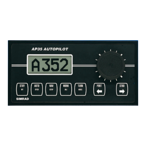
Units not in control will display "Inactive". The AP35 system is capable of the following primary steering modes: STBY (manual steering), AUTO, NAV, WORK and TURN, each mode having a dedicated push button. -
Page 18: On/Off - Standby Mode
Simrad AP35 Autopilot A group of user adjustable settings are provided in the AP35 USER SETUP MENU (page 27). The settings allows adjustment of display visibility, selection of heading sensors, navigation and position sources and the ability to select between automatic or manual adjustable sea state filter. -
Page 19: Follow-Up Steering
2.3 Follow-Up steering When both the PORT and STBD push buttons are pressed simultaneously the AP35 is set to Follow-Up steering mode and rudder commands can be set by the course dial. One revolution of the dial equals 45° rudder command. -
Page 20: R3000X Remote Control
Simrad AP35 Autopilot 2.7 R3000X Remote Control Note! When in AUTO/WORK mode, pressing SIMRAD the buttons will change the set course 1° per push. If you keep the button Push buttons for Port and Stbd NFU commands pressed, it will automatically change the course in increments of 3°/second. -
Page 21: Automatic Steering
AUTO mode. The AP35 will keep the boat on the set heading until a new mode is selected or a new heading is set with either the course dial or the PORT or STBD buttons. -
Page 22: Automatic Speed Selection
The AP35 automatically selects the HI or LO parameter set. The speed at which the AP35 changes from HI to LO (or opposite) is determined by the "Transition Speed" set in the Installation Setup Menu. -
Page 23: Navigating With The Ap35
The AP35 has the capability to use steering information from an external navigator (GPS, Chart Plotter) to direct the boat to a specific waypoint location, or through a route of waypoints. In the NAV mode, the AP35 uses the heading sensor as it's source of heading for course keeping. The steering and speed information received from the external navigator alters the set course to direct the AP35 to the destination waypoint. -
Page 24: Selecting A Different Navigator
When operating the AP35 in NAV mode to automatically steer through a route of waypoints, the AP35 will steer to the first waypoint in the route after you accept the first waypoint as the location to steer to. When you arrive at the waypoint, the AP35 will display an alert screen with the proposed new course information displayed. -
Page 25: Work-Mode
WORK button following that for the TRIM display will give access to the RUDDER display. The RUDDER value can then be set by the course dial. The RUDDER value set in WORK mode will be stored in the AP35 memory and is automatically recalled when returning to WORK mode. -
Page 26: Turn-Mode
PORT or STBD button to select the direction to make the U-Turn. If you do not press PORT or STBD within 1 minute, the AP35 will return to the AUTO mode and stay on course. -
Page 27: Dodging
When in DODGE mode the course displayed is the current boat's heading, however, the previous set course is remembered by the AP35. When DODGE is displayed, the AP35 is no longer in control of the steering, and you must either manually steer the boat or take control using either Non Follow Up steering or Follow Up steering. -
Page 28: Lock Function
Simrad AP35 Autopilot 2.17 Lock function The "LOCK" function is a safety feature included in the AP35 system to disable all control units except for a single, user selected control unit location. When the "lock" function is in use, no transfer of command may take place;... -
Page 29: User Set-Up Menu
GPS 1 - SETUP - Select the source of speed over ground (SOG) and position data processed by the AP35. This option will appear whenever there is POS. Source: more than one navigation receiver connected to the system. GPS 1 NMEA TEST? Test functions for analysing system data (See "NMEA test"... - Page 30 Simrad AP35 Autopilot This page is intentionally left blank. 22083083H...
-
Page 31: Technical Specifications
Technical Specifications 3 TECHNICAL SPECIFICATIONS 3.1 AP35 Autopilot System Boat size and type: ......Up to 45 feet, Power Steering system types: ....Hydraulic, Mechanical, Solenoids Inter-unit connection: .....ROBNET network or two-wire supply/data System ON/OFF:......From control units Supply voltage:.......See junction units Power consumption: .......Dependent on system configuration Environmental Protection: Control Unit:......IP56... -
Page 32: Ap35 Control Unit
Safe distance to compass:....0.5 m (1,6 ft) Temperature: Operating: .......0 to +55 °C (+32 to +130 °F) Storage:........–30 to +80 °C (–22 to +176 °F) Figure 3-1 AP35 Control Unit - dimensions Drw. no. N3-208305 3.3 Junction units Dimensions:........See Figure 3-2 and Figure 3-3 Weight: J300X/J3000X ......1,3 kg (2,9 lbs.) -
Page 33: Figure 3-2 J300X/J3000X Junction Unit - Dimensions
Technical Specifications NMEA input/output ports:....J3000X: 1 (one) J300X, J300X-40: 2 (two) External Alarm: ......Open collector Temperature range: Operation: ....... 0 to +55 °C (+32 to +130 °F) Storage:........–30 to +80 °C (–22 to +176 °F) Mounting: ........Bulkhead mount Material: .........Anodized aluminium and black ABS cover Figure 3-2 J300X/J3000X Junction Unit - Dimensions Figure 3-3 J300X-40 Junction Unit - Dimensions... -
Page 34: Rfc35 Fluxgate Compass
Simrad AP35 Autopilot 3.4 RFC35 Fluxgate compass Dimensions:........See Figure 3-4 Weight: ...........0,9 kg (2,0 lbs) Supply and output:......Polarity independent 2-wire supply with superimposed pulse width modulation Automatic Performance: Calibration: ......Automatically activated by control head Gain compensation: ....Automatically adjusted continuously Repeatability:........± 0.5 degrees Roll/Pitch:........±... -
Page 35: Rc25 Rate Compass
Technical Specifications 3.5 RC25 Rate Compass Dimensions:........See Figure 3-4 Weight: ...........0,9 kg (2,0 lbs) Power consumption: .......0,9 watts Supply and interface:......Robnet Environmental Protection:....IP56 Material: .........White ABS Temperature range: Operation:......0 to +55 °C (+32 to + 130 °F) Storage: ........–30 to +80 °C (–22 to +176 °F) Mounting: ........Deck or bulkhead Cable supplied: .......15 m (49’) Robnet cable with connector Automatic Performance:... -
Page 36: Ri35 Mk2 Rudder Angle Indicator
Simrad AP35 Autopilot 3.7 RI35 Mk2 Rudder Angle Indicator Dimensions:.......See Figure 3-5 Weight: ........1.0 kg Supply voltage:......12/24V DC –25%/+30%, polarity independent Power consumption: ....Max 3 W Input signal:.......Frequency 3400 Hz (midship reference), ±20Hz/degree, polarity independent Current: 0.1 - 1.1mA (midship 0,6mA), polarity independent NMEA 0183 RSA (min. -
Page 37: Rf300 Rudder Feedback Unit
Technical Specifications 3.8 RF300 Rudder Feedback Unit Dimensions:........See Figure 3-6 and Figure 3-7. Weight: ...........0,5 kg (1,1 lbs) Rudder angle: .........± 90 degrees Output signal: .........Polarity independent frequency signal Frequency resolution: .....Centre: 3400 Hz, 20 Hz/degree of change ± 3 degrees up to 45 degrees of rudder Linearity: Cable supplied: .......10 m twisted pair shielded cable Mounting: ........Horizontal, vertical, upside down... -
Page 38: Rf45X Rudder Feedback Unit
Simrad AP35 Autopilot 3.9 RF45X Rudder Feedback Unit Dimensions:........See Figure 3-8 Protection: ........IP56 Ambient temperature:.....–10 - +55°C Operating voltage: ......12V DC (autopilot supplied) Frequency output, Feedback: ..3400Hz (midship reference) Port: +20Hz/degree, stbd: -20Hz/degree Current output, Indicator ....0.1mA - 1.1mA Capacity:.........5 indicators in series Rudder angle: .........±45°... -
Page 39: R3000X Remote
Technical Specifications 3.10 R3000X Remote Dimensions:......... See Figure 3-10 Weight: ..........0,4 kg (0,9 lbs) Material: ......Epoxy-coated aluminum Protection .............. IP56 Safe distance to compass: ..... 0.15 m (0.5 ft.) STBY AUTO Temperature range: Operating: ....–25 to +55°C (–13 to +130°F) Storage: ......–30 to +80°C (–22 to +176°F) Cable:...........7 m (23 ft.), shielded Mounting bracket:........... -
Page 40: Ni300X Nmea Interface
Weight: ...........0,9 kg (2,0 lbs) Power consumption: .......3 W NMEA183 input/output:....4 ports, max output load 20 mA Heading output: ......Simrad/Anritsu and Furuno radar display (clock/data, 0-5V, 50 msec.) NMEA instrument supply: .....12V DC, max 0.25A Robnet network interface: ....2 network connectors Cable inlets:........Rubber glands for cable diam 10-14 mm... -
Page 41: F1/2 Remote Control
Technical Specifications Figure 3-12 S35 - Dimensions 3.14 F1/2 Remote Control 76 (3.0") Dimensions:....See Figure 3-13 65 (2.6") Protection: ....IP56 Cable length:....10 meters (30 ft.) Max. inductive load:.. 4A/24V DC, 60mA/110V AC, 25mA/220V AC. Figure 3-13 F1/F2 - Dimensions 22083083H... -
Page 42: Fu50 Steering Lever
Simrad AP35 Autopilot 3.15 FU50 Steering Lever Dimensions:.......See Figure 3-14. Handle can be mounted pointing upwards or downwards. Weight: ......1.2 kg (2.6 lbs.) including cable Material: ......Polyacetal (POM) Environmental protection: .IP56 Power consumption: ..3W Safe distance to compass:..0.15 m (0.5ft.) Temperature: Operating:....–10 to +55°C (+14 to +130°F) -
Page 43: Ip Protection
Technical Specifications 3.16 IP protection Each part of a Simrad autopilot system has got a two digits IP protection code. The IP rating is a method to classify the degree of protection against solid objects, water ingress and impact afforded by electrical equipment and enclosures. - Page 44 NMEA messages and data overview for IS15, AP11, AP20, AP35, AP300X, AP3000(X) and J3xx V1R8 Remarks: Indata use Bold red font = {IS15, J3xx and IS11Multi} M=IS11 Multi only, black regular font = {J3xx and IS15}. Message ident. Blue 'X' IS15 only. Shadowed not to be used...
-
Page 45: Installation
This section provides detailed information required to successfully install AP35 Autopilot system The AP35 system includes several modules that need to be mounted in different locations on the boat, and also need to interface with at least three different systems on the boat: •... -
Page 46: Unpacking And Handling
• RF300 Feedback unit with 10 m (33') cable attached and transmission rod. • Appropriate drive unit for the installation (unless the AP35 is going to operate an existing drive unit) • Optional equipment that may have been ordered for the installation. -
Page 47: Ap35 System Layout
Installation 4.5 AP35 System Layout Figure 4-1 AP35 System layout with options 4.6 RF300 Rudder feedback The RF300 Rudder feedback unit mounts close to the rudders, and is mechanically linked to the rudder tiller arm or rudder quadrant. Refer to Figure 4-2 for the recommended mounting arrangement. Note that the RF300 transmitter arm has two slots for the transmission link. -
Page 48: Figure 4-2 Rf300 Mounting (019356)
Simrad AP35 Autopilot Attach the transmitter rod to the RF300. Set the RF300 mounting location to be in accordance with Figure 4-2. The centre of the RF300 should be in line with the centre of the rudder post. Mount the RF300 to a suitable platform using the screws provided. -
Page 49: Rf45X Rudder Feedback Unit
Installation 4.7 RF45X Rudder Feedback Unit The RF45X is normally installed with the shaft pointing upwards. It can, however, be mounted with the shaft pointing downwards if this is more convenient. The deflection can then be inverted as illustrated in Figure 4-5. An “upside-down”... -
Page 50: Electrical Connection
Simrad AP35 Autopilot Electrical connection Use a twisted pair cable AWG20 (0.5 mm ) between the breakout box and the J3xx junction unit. The cable length is not critical but should be kept at a minimum. The cable should be connected to the junction unit according to Figure 4-5. -
Page 51: Junction Unit
Installation 4.8 Junction unit The junction unit is designed to operate in a location that provides ambient temperatures below +55°C (+130°F). Note ! The junction units (J3000X, J300X and J300X-40) are not water proof and should be mounted vertically as shown in a dry place between the control unit and the drive unit. -
Page 52: Grounding And Rfi
Simrad AP35 Autopilot Grounding and RFI The AP35 system has very good RFI protection and all units are using the Junction Unit as common ground/shield connection. The Junction Unit should therefore have a proper ground connection to the hull. ROBNET cables and other signal cables (compass, feedback, NMEA) should not be run in parallel with other cables carrying RF or high current, such as VHF and SSB transmitters, battery chargers/generators and winches. -
Page 53: Drive Unit
The relation between drive units, drive unit voltage, input voltage, drive output and interfacing to steering gear are shown in the table below. The AP35 system detects whether a reversible motor or a solenoid is connected and outputs the correct drive signal automatically. - Page 54 Simrad AP35 Autopilot LINEAR DRIVE UNITS MODEL MOTOR JUNCTION PEAK HARD- PWR. TILLER VOLTS UNIT STROKE THRUST RUDDER OVER CON- mm (in.) kg (lb.) TORQUE TIME SUMP. sec. (in.) (lb.in.) (30% load) MLD200 J3000X 300 (11,8) 1,5-6 A (440) (4350)
-
Page 55: Connecting A Reversible Pump
Installation Note ! When selecting DRIVE UNIT voltage in the Installation setup, the clutch/bypass voltage is always set equal to the motor voltage. If a retrofit installation where e.g. a HLD2000 has a 12V motor and a 24V bypass valve, the bypass valve solenoid has to be changed back to standard 12V version. -
Page 56: Connecting A Solenoid Valve
• Connect the Robnet cables to the control unit connectors (See note on next page). Figure 4-11 AP35 Panel mounting Bracket mounting • Mount the two bracket halves to the Control unit. • Temporarily bolt together the other two halves of the bracket to the two other halves. -
Page 57: Robnet Network Cables
• Connect the Robnet cables to the control unit connectors (See note on next page). Figure 4-12 AP35 Bracket mounting ROBNET network cables As Robnet units have 2 Robnet connectors they can be used as "jack points"... -
Page 58: Figure 4-13 Control Unit Connection
Simrad AP35 Autopilot CONTROL CONTROL CONTROL CONTROL UNIT UNIT UNIT UNIT JUNCTION JUNCTION NI300X NI300X UNIT UNIT All connectors are crimp type, which can be easily dismantled if required in an installation where you can not drill holes as big as the connector is. -
Page 59: Rfc35 Fluxgate Compass
4.11 RFC35 Fluxgate Compass Figure 4-14 RFC35 mounting The heading sensor is the most important part of the AP35 system and great care should be taken when deciding the mounting location. As the sensor heading is displayed on the AP35 Control Unit, the heading sensor can be mounted at any location where there is a minimum of magnetic interference. -
Page 60: Rc25 Rate Compass
RFC35. On steel hull boats, however, it should be installed 1 meter above the steel deck to obtain optimum performance. RATE AP35 COMPASS CONTROL UNIT Figure 4-16 RC25 Connection to AP35 Control Unit 22083083H... -
Page 61: R3000X Remote Control
Installation • Connect the Robnet connector to the AP35 Control Unit (or CI300X or NI300X if installed), see Figure 4-16. • Alternatively, if there is no free receptacle, cut the connector from the cable and connect the wires in parallel with the wires going from the junction unit to the control unit (see Figure 4-13). -
Page 62: S35 Nfu Steering Lever
Simrad AP35 Autopilot 4.15 S35 NFU Steering Lever The unit is mounted to bulkhead or panel by two screws from the front. The cable is connected to the junction unit according to Figure 4-18. Interchange the port and stbd wires to the screw terminals in the junction unit if necessary to make the direction of the lever movement coincide with the direction of the rudder movement. -
Page 63: Ri35 Mk2 Rudder Angle Indicator
Mounting of RI35 Mk2 is identical to the mounting of AP35 Control Unit; refer to page 54. When the location is determined, the cables should be connected to RI35 Mk2 before the unit is mounted. -
Page 64: Reversed Deflection
Simrad AP35 Autopilot Reversed deflection On installations where the rudder feedback unit is mounted upside down, the deflection of the pointer will be reversed. To make it correct, move the rudder to approximately 10° either way then press and hold the illumination key for 10 (ten) seconds. -
Page 65: Interfacing
Installation 4.18 Interfacing With the AP35 autopilot system there are several possibilities to connect to other equipment for data exchange: 1. J3000X includes a single NMEA input/output port. 2. J300X includes two NMEA input/output ports (NMEA heading 10 Hz to port 2) and Clock Data interface to Simrad/Anritsu and Furuno radars. -
Page 66: Additional Nmea Output On Port 2
Simrad AP35 Autopilot 4.21 Additional NMEA output on Port 2 Output signal Output terminal Output sentence Continuous output of Junction unit, Power PCB, HDT (True) or HDG compass heading on 10 Hz NMEA2, TX2+, TX2– (Magn.) depending (10x/sec.) NMEA format on heading source. -
Page 67: Is15 Instrument
Installation 4.24 IS15 Instrument For installation and operation of the IS15 instruments refer to separate manuals. NMEA In This connection will provide speed and depth input to the autopilot. If an IS15 Wind Transducer is connected to the system, wind information will also be transferred to the autopilot. -
Page 68: Analog Repeater
Simrad AP35 Autopilot 4.25 Analog Repeater Figure 4-27 AR77 and AR68 Analog Repeater connection 4.26 Digital Repeater Figure 4-28 DR75 Digital Repeater connection 22083083H... -
Page 69: External Alarm
NMEA ports are available. An additional output data-port with DATA/CLOCK signal is capable of generating heading data in the format used by some radar displays made by Simrad/Anritsu and Furuno. This feature is thus added to the system if a J3000X Junction Unit is installed (J3000X has no radar Clock/Data output as compared to J300X and J300X- 40). -
Page 70: Ci300X Analogue Interface Unit
The CI300X analogue interface unit is an optional module, designed to enable a variety of different equipment to connect into AP35 systems. The CI300X converts the analogue inputs into Robnet compatible signals for use by AP35 system components. The CI300X adds the following capabilities to... -
Page 71: Cd100A Course Detector
Installation For detailed information, see separate CI300X Manual. CI300X COMPASS INTERFACE ALARM ROBNET OUTPUT CONNECTIONS (Normally open) RGC10/RGC50 ENAB GYRO COMPASS NON FOLLOW UP PORT STEERING STBD LEVER FLUXGATE COMPASS WITH SINE/COSINE OUTPUT DC SUPPLY MAGNETIC COMPASS CD100 CONNECTIONS: WITH CD100A COURSE ALT. -
Page 72: Cdi35 Interface
Simrad AP35 Autopilot Screw M6x25mm, non magnetic Washer, non magnetic Course detector Cable clamp, nylon Washer, non magnetic Screw M3x10mm, non magnetic Note! Lock nut on mounting screw (pos. 1) for transportation only. To be removed before mounting. Figure 4-32 CD100A mounting 4.31 CDI35 Interface... -
Page 73: Software Setup Procedure
Each group is designed to focus on specific functions related to an installation activity, and enable quick access when changes need to be made. Some important points regarding the installation settings values: • When the AP35 is delivered new from the factory, (AND ANY TIME AFTER MASTER... -
Page 74: Installation Settings Menu
• Leave the ISM by selecting STBY, AUTO, WORK or NAV. On new installations, and whenever a control unit, junction unit, or software is replaced in an AP35 system, it is recommended that a MASTER RESET be performed as described in the ISM prior to proceeding with the setup procedure. -
Page 75: Dockside Settings
Installation ENTER INSTALLATION SETTINGS MENU BY PRESSING SYMBOLS AND HOLDING THE NAV BUTTON FOR 5 SECONDS SELECT OR CONFIRM BY LANGUAGE ITEMS INSTALLATION ROTARY COURSE SELECTOR MENU ENGLISH NORSK GO TO NEXT MENU ITEM STBD FRANCAIS BY PRESSING STBD BUTTON ESPANOL LANGUAGE ? ITALIANO... -
Page 76: Drive Unit Voltage Selection
The CLUTCH/BYPASS voltage is automatically set to the same as the drive unit voltage. In Rudder Test, the AP35 system will also automatically detect whether the drive unit is a reversible motor or solenoid operated. -
Page 77: Alignment For Rf45X Rudder Feedback Unit
Installation INSTALLATION Rudder feedbk calibration? Alignment for RF45X Rudder Feedback Unit The purpose of this procedure is to find the zero point and make the feedback unit operate within its active segment. If the unit operates outside this segment there will be a feedback failure alarm. - Page 78 Simrad AP35 Autopilot INSTALLATION Turn rudder max. STBD Adjust? The value shown on the display is the value read by the feedback unit before any adjustment is made. The arrow indicates to which side the rudder is positioned. If the displayed angle is different from the actual angle, set correct rudder angle on the display by turning course selector clockwise to increase the value or counter clockwise to decrease the value.
-
Page 79: Automatic Rudder Test
Activate the automatic rudder test by turning the course selector clockwise. The AP35 will issue a series of PORT and STBD rudder commands and automatically verify correct motor direction, and reduce the rudder speed if it exceeds the maximum acceptable speed for autopilot operation. -
Page 80: Autotrim Work
Simrad AP35 Autopilot If no speed data is available on either the INSTR channel (VHW) or the POS source (VTG), manual speed selection is required. The AP35 will always default to the HI speed steering parameters when the system is first turned on, and with speed data failure. -
Page 81: Interface Settings
Interface Settings The AP35 system provides a totally flexible approach to the input of data from heading sensors and other peripheral equipment. Identification of the type of equipment connected to the AP35 system is performed in the Interface Setup Menu. - Page 82 Each abbreviated name is then presented in appropriate locations of the USER SETUP MENU to provide the user with choices of data sources, or identified to the AP35 where to look for various types of data.
- Page 83 Installation Interface setup - input signal Setup item Equipment Connected to terminal Assign hardware (abbrev. connected (use one available from list) port to setup item name) (* = default setting) GPS1 Not connected – J3XX, Main PCB NMEA I/P J300X-1 * RX1+,RX1–...
- Page 84 Simrad AP35 Autopilot Setup item Equipment Connected to terminal Assign hardware (abbrev. connected (use one available from list) port to setup item name) (* = default setting) NAV2 Not connected – * J300X, Main PCB NMEA I/P J300X-1 RX1+,RX1– J300X, Power PCB NMEA I/P J300X-2 RX2+,RX2–...
-
Page 85: Sea Trial
It is also recommended that the Interface Setup be performed prior to Seatrial settings. The seatrial settings do the following: • Rudder zero adjust (To tell the AP35 the precise midships position of the rudder) • Compass calibration (To automatically compensate for onboard magnetic Deviation) •... -
Page 86: Compass Calibration
COMPASS OFFSET setting to input a fixed correction to the heading readout. Press STBD [>] button to proceed to next menu item. Note ! If an optional NMEA compass from Simrad or other manufacturer is installed, refer to the optional compass manual regarding calibration. Compass Offset... -
Page 87: Automatic Tuning
Dockside Settings menu. Note ! Autotune is an optional procedure that is not required for the AP35 to function. The AP35 is preset with steering parameters that should steer most boats in the 30 - 50 foot range and Autotune may not be required if the preset parameters steer your boat acceptably. -
Page 88: View Parameters
Viewing or changing the Autotune parameters are done from within the VIEW PARAMETERS menu item. Exit the Seatrial Settings menu by pushing STBD [>] button to proceed to the View parameters menu, or press STBY to return to normal AP35 operation. View parameters... -
Page 89: Manual Parameter Adjust
Installation Manual parameter adjust Own boat BOAT TYPE: Displayed parameter Displacement Planing Autotune Manual Use course dial to adjust LOw speed parameters Rudder LO Cont Rudd LO Autotrim LO PORT STBD Rudder lim LO HIgh speed Rudder HI 0.35 Cont Rudd HI Use PORT and STBD buttons to Autotrim HI... -
Page 90: Final Sea Trial
Simrad AP35 Autopilot Counter Rudder is the parameter that counteracts the effect of the boats turn rate and inertia. For a short time period it is superimposed on the normal rudder response as provided by the Rudder parameter. It may sometimes appear as if it tends to make the rudder move to the wrong side (counter rudder). -
Page 91: Providing User Training
Port and Stbd steering commands of the lever. • Set waypoints into each navigator connected to the system, and verify that the AP35 steers in NAV mode for each NAV source. • Provide the owner with user training. -
Page 92: Maintenance
Simrad AP35 Autopilot 5 MAINTENANCE 5.1 Control unit The AP35 Control Unit will under normal use require little maintenance as the cases are made from seawater resistant aluminium and has a polyester coating to withstand the rigours of an exposed cockpit. -
Page 93: Exchange Of Software Programme
Figure 5-1 J3000X/J300X/J300X-40 Main PC-Board AP35 Control Unit EPROM Figure 5-2 AP35 PCB, component layout • Remove the EPROM from the socket by means of the special extraction tool (p/n 44139806) • Insert the tool by pressing the two grip pins down into the two slots in the corners of the socket. -
Page 94: Modification On Ap35 Pcb
Refer to our Technical bulletin no. 10/97. The modification is valid from PCB S/N 913 and onwards. Modified PCBs are not compatible with former S/N code ---A70 of the control unit. All AP35 Control Units from S/N 905A71 onwards have got modified PCBs, and accordingly they have got the new A71 code. -
Page 95: Trouble Shooting
An autopilot is a complex system and the performance is dependent of a proper installation and a successful sea trial. In the event of a failure, you will be helped by the AP35 software which contains several test features that will assist you in isolating a probable fault. - Page 96 Simrad AP35 Autopilot Display readout Probable fault Recommended action Rudder test failed Rudder test not completed a) Check connections (cont’d) within 2 min. b) Replace PCB a) Poor connections to c) Check PCB for traces of burnt drive unit transistors. – Change PCB.
- Page 97 Trouble Shooting Display readout Probable fault Recommended action Bypass/clutch Clutch/bypass current 1. Check actual current overload exceeds 2,5 Amps 2. Check voltage marking on coil (overload or short circuit). 3. Check coil resistance (through connecting wires) Bypass/clutch Poor connection or open 1.
-
Page 98: Nmea Test
Simrad AP35 Autopilot 6.2 NMEA Test The NMEA test menu is accessed from the User Set Up Menu (page 27). It provides you with status information of the different NMEA messages used in the system. Decoding - SETUP - incoming... -
Page 99: System Data Menu
Trouble Shooting 6.3 System Data Menu The menu is accessed from the User Set up Menu (page 27). It provides you with additional system data that can be useful when testing or trouble shooting the system. NMEA hardware test On the Main PCB in the junction unit disconnect the cables and connect TX1+ to RX1+ and TX1- to RX1-. -
Page 100: Spare Parts List
Simrad AP35 Autopilot 7 SPARE PARTS LIST 22082911 AP35 Control Unit 22082937 AP35 Control Unit 22082929 Installation accessories 22082945 AP35 Front Housing Ass’y 22082853 Back cabinet 22082804 AP35 Board Ass'y 44162840 Cover for plug 22082978 PROM (programmed) V..R.. Junction Units... - Page 101 Spare Parts List 44140770 Screw 30x9 (4) 22081376 Plug (2) 22084370 RC25 PCB Ass'y 22082440 Cable, 15 m with Plug RF300 Rudder Feedback Unit 20193462 RF300 Rudder Feedback 20193470 RF300 transmission lever 20193454 RF300 transmission link 44133122 Transmission rod M5x325mm 20193624 RF300 Ball joint Ass'y (2) RF45X Rudder Feedback Unit...
- Page 102 Simrad AP35 Autopilot 22084016 RI35 Mk2 Front Housing 22083992 RI35 Mk2 Back Cover 44164135 Blind plug 44140796 Cable gland 44141174 Seal (o-ring) 44140812 Screw, 3x7 mm 44148898 Screw, M4x12 22083307 Spacer 44163699 Plug-in terminal, 2 pole 44119154 Diode LED Green HLMP 1540...
-
Page 103: Sales And Service Worldwide (300903)
Fax: +47 55 94 10 05 Tel.: +46 31 69 51 00 Fax: +31 181 626688 Fax: +46 31 69 51 20 GERMANY POLAND CROATIA Simrad GmbH & Co. Escort Ltd. Electronics SWITZERLAND Almar d.o.o. Syst. Marine Parts Porec - Kamenarija 12 Dithmarscher Strasse 13 Ul. - Page 104 Simrad AP35 Autopilot SOUTH AFRICA JAPAN BRAZIL ASIA Marine Radio Acoustic Nippon Kaiyo Co, Ltd. Demo Offshore Ltda Devices 9-2 Sakae-Cho Av. Marechal Camara SINGAPORE Jason Electronics Pte P. O. Box 12076 Kita-Ku Ltd. N1 City 7463 Tokyo 114-0005 Sala 614,...
Need help?
Do you have a question about the AP35 and is the answer not in the manual?
Questions and answers
Need help on setting up ap35 autopilot
To set up the Simrad AP35 autopilot:
1. Mounting Components: Install the control unit and CDI35 interface. Mount the CDI35 close to the compass and secure it using fixing screws. Connect cables as shown in the wiring diagram.
2. Software Installation Settings: During installation, access the installation settings menu. Set values including language and navigation sources. These settings are necessary for proper system function.
3. Autotune: If needed, perform Autotune in open water:
- Use a safe, open area with no nearby traffic.
- Recommended speed: below 10 knots, or about half cruising speed for displacement boats.
- Avoid planing speed.
- Best results are achieved when heading East or West.
- Autotune takes 1–2 minutes and performs S-turns.
- It sets LO speed parameters; HI speed is set to 66% of LO.
4. User Setup Menu: Adjust user settings like display visibility, heading sensor selection, and navigation sources.
5. Safety: Always verify course and position regularly, switch to Standby mode, and reduce speed in time to avoid hazards.
This answer is automatically generated
I have a simrad ap35 autopilot .somt know why when I turn to the right it can goes up to 70 but when o turn left it only goes up to 35 .
The likely reason for the Simrad AP35 autopilot turning more to the right (up to 70) than to the left (only up to 35) could be incorrect zero adjustment or reversed deflection settings of the rudder feedback unit. If the feedback unit is mounted upside down and not properly configured, it can cause incorrect pointer deflection and unequal steering response. Performing a reversed deflection correction or redoing the zero adjust may resolve the issue.
This answer is automatically generated