Simrad AP50 Operator's Manual
Hide thumbs
Also See for AP50:
- Instruction manual (188 pages) ,
- Installation manual (134 pages) ,
- Installation manual (142 pages)
Table of Contents
Advertisement
Quick Links
Advertisement
Table of Contents

Related Manuals for Simrad AP50


Summary of Contents for Simrad AP50
- Page 1 OPERATOR MANUAL SIMRAD AP50 Autopilot 20221032/E Sw. 1.3 English...
- Page 2 Panorama Mk2 indicators included. Rev. D The AP50 Instruction Manual was splitted into one Operator Manual and one Installation Manual. Manuals updated according to software version 1.3. S9 Steering Lever, QS50 Quick Stick and JD5X Distribution Unit included in the System Description section.
- Page 3 System and a Plus System. Great care has been taken to simplify the set-up and operation of the AP50; however, an autopilot is a complex electronic system. It is affected by sea conditions, speed of the vessel, and vessel hull shape and size.
-
Page 4: Table Of Contents
RI35 Mk2 Rudder Angle Indicator..............7 RI9 Rudder Angle Indicator ................8 NI300X NMEA Interface Unit ...............8 OPERATION OF THE AUTOPILOT ..............9 Overview ......................9 ON/OFF - Standby Mode (STBY) ...............12 AP50 with MSD50 Stern Drive unit.............14 Zero point setting..................14 Operation ......................14 20221032 / E... - Page 5 S35 NFU Steering Lever ................16 Automatic Steering ..................17 AUTO Mode....................17 AUTO-WORK Mode ...................18 Thruster Steering ..................19 Navigating with the AP50 ................20 Route Navigation..................22 Setting the waypoint arrival circle..............22 Electronic Chart System (ECS) ..............23 Selecting a Different Navigator ..............24 NAV-WORK Mode..................24 Dodging ......................25...
- Page 6 Simrad AP50 Autopilot MAINTENANCE ....................41 Control unit....................41 Junction Unit....................41 Rudder Feedback ..................41 Compass (RC25)...................41 Drive unit ......................41 Exchange of software program..............42 TROUBLESHOOTING ..................45 Warnings.......................45 GLOSSARY......................51 INDEX........................54 20221032 / E...
-
Page 7: System Description
Any unit that is connected to the autopilot system via Robnet is called a Robnet Unit. The AP50 system is produced and tested in accordance with the European Marine Equipment Directive 96/98. This means that the AP50 complies with the highest level of tests for non- military marine electronic navigation equipment existing today. -
Page 8: How To Use This Manual
Simrad AP50 Autopilot Simrad has no responsibility for the incorrect installation or use of the AP50 autopilot, so it is essential for the person in charge of the installation to be familiar with the relevant requirements as well as with the contents of this manual, which covers correct installation and use. -
Page 9: System Components
System Description 1.3 System Components A basic AP50 system may consist of the following units (refer to Figure 1-1): • AP50 Control Unit with accessories • Heading Sensor • Rudder Feedback Unit with transmission link • Junction Unit • Drive Unit The basic system can be expanded with remote control unit, hand held remote and steering lever. -
Page 10: Jd5X Distribution Unit
2 sets of limit switches. 1.8 Heading Sensors The AP50 autopilot system can be used with the following combinations of heading sensors: RC25 Rate Compass The fluxgate compass with an integrated rate of turn sensor provides a dramatic improvement to the dynamic performance of both the autopilot and any stabilized radar display. -
Page 11: Cd100A Course Detector And Cdi35 Course Detector Interface
A series of options are available for the AP50 system. AP51 Remote Control This portable remote control unit for AP50 with 7 m (23 ft.) of cable can be used as a hand-held remote control or can be mounted in a fixed bracket-mount. -
Page 12: R3000X Remote Control
S9 permits locking of the lever in the mid-position to avoid inadvertent operation. When the S9 handle is pulled out, the autopilot will be disengaged. When connected to the AP50, the S9 can also be wired for direct NFU override steering. 20221032 / E... -
Page 13: Fu50 Follow-Up Steering Lever
Robnet from other system units. Set-up from the control unit and errors in the thruster interface are communicated via the Robnet. All thruster settings in the AP50 Control Unit are stored in the thruster interface unit. Refer to the TI51 manual. -
Page 14: Ri9 Rudder Angle Indicator
NI300X NMEA Interface Unit This interface unit with 4 NMEA In/Out ports for communication with other systems and a selectable heading output for radars (Anritsu or Furuno), includes two Robnet connectors for the AP50 system. 20221032 / E... -
Page 15: Operation Of The Autopilot
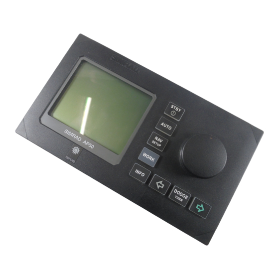
Inactive RUDDER 340. SETUP Gyro1 WORK DODGE SIMRAD AP50 INFO TURN Figure 2-1 AP50 Front Panel Buttons Action Function Short press: Switches the system on. Selects STANDBY mode. Long press (3 sec.): Switches the system off. STBY Quick double press: Locks or unlocks other control units and levers in the system. - Page 16 Simrad AP50 Autopilot Buttons Action Function Single short press: Selects AUTO mode and sets the heading reference. AUTO Second short press Sets new heading reference (Heading catch) Short press: Selects NAV mode prompt screen from AUTO mode. Verifies new course to steer when alert screen is shown (can also use the course knob, see below).
- Page 17 Operation Buttons Action Function Press simultaneously Activates Follow-up steering mode. Rotate in Follow-up Sets commanded rudder angle. steering mode: Rotate in AUTO Counter clock-wise = Port course change mode: Clock-wise = Starboard course change Rotate in NAV Verifies new course to steer when alert screen is mode: shown.
-
Page 18: On/Off - Standby Mode (Stby)
A group of user-adjustable settings belonging to the selected mode are provided in the AP50 User Set-up Menu (see page 29). The settings allow adjustment of display visibility, selection of heading sensor, navigation and position sources, and the ability to select between automatically or manually adjustable sea state filter. - Page 19 Operation Junction unit model Simrad Software version (1), release (3), minor change (00) SW 1.3.00 P05 M00 S000 Power board revision, Main board revision and Self check (SW and HW revisions shown are examples only) After approximately 5 seconds, the system is operative and the unit that was turned on will show the STANDBY mode display.
-
Page 20: Ap50 With Msd50 Stern Drive Unit
Simrad AP50 Autopilot 2.3 AP50 with MSD50 Stern Drive unit Note ! The information in section 2.3 only applies if your autopilot is driving a Simrad MSD50 Stern Drive. The MSD50 Stern drive unit has a relative feedback signal which needs a zero point setting after the autopilot has been turned on. -
Page 21: Follow-Up (Fu) Steering
When both the (PORT) and (STBD) buttons are pressed simultaneously, the AP50 will enter Follow-Up steering mode and the course knob may be used to set rudder commands. One revolution of the knob equals a 45° rudder change. The rudder will move to the selected angle and stop. -
Page 22: Js10 (Nfu) Joystick
: The set course will be changed by 3° per second when the lever WORK is offset to Port or Starboard or 1° for single activation. Changing set course is indicated by beeps on the AP50 Control Unit. The mode button remains lit as long as the autopilot is in AUTO or AUTO-WORK mode (and NAV mode). -
Page 23: Automatic Steering
AUTO automatically on a set heading. AUTO mode is always available from any mode or function within the AP50 by a single push of the AUTO button. When AUTO mode is selected, the AP50 automatically selects the current vessel heading as the set heading and the rudder will move to midship position. -
Page 24: Auto-Work Mode
Simrad AP50 Autopilot A329 Display information: • Automatic steering mode • Set heading: 329° RUDDER 340. • Boat heading from gyro compass: 340.7° Gyro1 • Rudder angle: 2° to port and still moving Rotate the course knob to change the course:... -
Page 25: Thruster Steering
2.7 Thruster Steering If the vessel is equipped with a thruster, it can be connected to the AP50 system and the vessel can then be controlled by rudder, thruster, or both rudder and thruster. After connecting a thruster to the autopilot system (see the TI51 manual) the thruster type must be selected under the Installation Dockside menu (ref. -
Page 26: Navigating With The Ap50
(Refer to the Installation Manual, Installation Menu/Settings/ Thruster/Thruster Sens). 2.8 Navigating with the AP50 The AP50 has the capability to use steering information from an external navigator (GPS/Chart plotter or ECS) to direct the boat to one specific waypoint location or through a series of waypoints. - Page 27 • At least one waypoint must be entered and selected as the current waypoint in the navigation receiver • The navigation source in the AP50 User Set-up menu must be set for the navigator that contains the current waypoint The AP50 is designed to steer in mixed mode operation. This...
-
Page 28: Route Navigation
If you use a GPS/Chart plotter, the AP50 will, when you arrive at 100° the waypoint arrival circle, output an audible alarm and display 035°... -
Page 29: Electronic Chart System (Ecs)
Electronic Chart System (ECS) An ECS has to be selected as NAV source. SETUP Press the NAV button to activate the NAV prompt display. SIMRAD The upper half of the prompt display shows the name of the next 270° BWW : waypoint (WP), the bearing to the waypoint (BWW), and the 70°... -
Page 30: Selecting A Different Navigator
Caution ! If an ECS is selected as a navigator, the course change verification is waved. This is done so the AP50 is capable of following a route in which the radius of the course change is pre-set in the chart system. Users navigating in this mode must use extra caution. -
Page 31: Dodging
A329 example, as A329 degrees) and this set course is remembered by DODGE the AP50. When DODGE is flashing on the display, the AP50 is RUDDER no longer in control of the steering and you must either steer the 340. -
Page 32: Dodging In Nav Mode
.023 previous set course is stored by the AP50. When DODGE is NEXT WP flashing on the display, the AP50 is no longer in control of the 340. SIMRAD steering and you must either steer the boat manually or take °M... -
Page 33: Turn Mode
A long press of the (DODGE/TURN) button activates U- DODGE DODGE T UR N T URN Turn. The AP50 will continue on the set course until you press either U TURN (PORT) or (STBD) button to select the direction in PORT Press STBD which to make the U-turn. -
Page 34: Multiple Station System
In the normal operation of multiple control units, control is accessible from every control unit and steering handle connected Inactive to the AP50 system. However, only one control unit is "active" RUDDER 340. at a time providing the user with access to all functions and... -
Page 35: Master Operation
Operation The display on the "active" control unit will first show a single 340. key icon followed by the primary display on which the key icon Gyro1 will alternate with the mode index (not when selected as Master station). RUDDER Active control unit The “LOCK”... -
Page 36: External System Selection
“Disengaged” on the display (no mode indicators are lit on the FU50). When automatic steering is selected, the AP50 will go to AUTO mode (or AUTO-WORK mode). For connection of an external system selector switch, refer to “System Select”, in the AP50 Installation Manual. -
Page 37: Auto Mode
AUTO mode and NAV mode the rudder is always selected. Speed (Man, Log, SOG) The AP50 adapts to the speed of the vessel and this setting should be adjusted accordingly. If a speed log or other speed source is not connected, the speed input can be set manually by the course knob with range from 1 to 70 Knots. - Page 38 Simrad AP50 Autopilot Steering Function (only available if Thruster is selected in the Installation Dockside Menu, see the AP50 Installation Manual). Same procedure as in STANDBY mode. Seastate Seastate determines the number of degrees the vessel may fall off the set course before any rudder commands are given to the rudder.
- Page 39 Operation Speed (Man, Log, SOG) SETUP Move : Adjust : Same procedure as in STANDBY mode. Speed Log 04.9kt Off heading lim 03° 341° Turn mode Off Heading Lim RateOfTurn 240°/min 340.7 Thruster sens 01° Off Heading Lim sets the limit for the Off Heading Alarm. An Gyro1 More alarm occurs when the actual heading deviates from the set...
-
Page 40: Auto-Work Mode
340.7 Gyro1 More Use the course knob to change value. These values are stored in the AP50 memory and are automatically recalled when returning to AUTO-WORK mode. Use the course knob to adjust the trim value, if needed. The SETUP... -
Page 41: Nav-Work Mode
Port and Stbd buttons. Use the course 340.7 W Count Rudder 1.40 Gyro1 More knob to change value. Selected values for Seastate filter, Rudder, and Counter Rudder are stored in the AP50 memory and are automatically recalled when returning to NAV-WORK mode. 20221032 / E... - Page 42 Simrad AP50 Autopilot Use the course knob to adjust the trim value, if needed. The SETUP Move : Adjust : manual trim setting compensates for the Autotrim, which takes Trim P01° time to execute the appropriate rudder offset. Speed Log 04.9kt...
-
Page 43: Instrument Screens And Menu
Move through the available instrument screens by repeatedly pressing the (INFO) button. The right-hand side of the INFO display will show the following instrument screens: BPW 272°T GPS1 COG 274°T SOG 2.40kt 04.9 SIMRAD 0.023NM 32.2NM Gyro1 274° RUDDER DEPTH 199.5m Main... - Page 44 Simrad AP50 Autopilot GPS1 POSITION WIND DIRECTION TRUE WIND 27.209 N 58° 58.322 E 005° 274°T 046° 046° 12.40kt WP SIMRAD 272 °T 32.2 NM Stern 0.012 NM Nav Data Wind direction True wind WIND APPARENT THRUSTER 046° RUDDER RUDDER...
-
Page 45: Screen Selection
Operation Screen Selection If you do not need all of the instrument screens to be present in the screen menu, you may temporarily remove screens by quickly double-pressing the (INFO) button. Move through INFO the screens by pressing the (PORT) and (STBD) buttons. - Page 46 Simrad AP50 Autopilot This page is intentionally left blank 20221032 / E...
-
Page 47: Maintenance
Maintenance 3 MAINTENANCE 3.1 Control unit Under normal use, the AP50 Control Unit will require little maintenance. The case is made from seawater resistant aluminum and it has a polyester coating to withstand the rigorous conditions of an exposed cockpit. It is recommended that units kept clean of salt, since salt will corrode metal over time. -
Page 48: Exchange Of Software Program
Simrad AP50 Autopilot 3.6 Exchange of software program Junction Unit PROM Figure 3-1 J50/J50-40 Main PCB, Component Layout AP50 Control Unit PROM Figure 3-2 AP50 PCB, Component Layout 20221032 / E... - Page 49 - the Simrad part number - the software version Caution ! Make sure that the correct PROM is mounted in each unit: PROM for the AP50 Control Unit: P/N 20212189 PROM for the J50 and J50-40 Junction units: P/N 20211934 •...
- Page 50 Simrad AP50 Autopilot This page is intentionally left blank. 20221032 / E...
-
Page 51: Troubleshooting
An autopilot is a complex system. Its performance depends on a proper installation and a successful sea trial. In the event of an autopilot failure, the AP50’s numerous test features will assist you in isolating a probable fault. Audible and visual alarm is provided for every fault being detected. - Page 52 JD5X, refer to the troubleshooting (The system will section in the AD50 manual or the switch to Stby − Missing power AP50 Plus Installation Manual. mode) − Rudder feedback not 1. Check all connections. moving with rudder 2. Check Rudder FB...
- Page 53 Troubleshooting Display readout Probable fault Recommended action Rudder test failed Rudder test not a) Check the connections. completed within 2 min. (continued) b) Replace the Main PCB a) Poor connections to c) Check the Power PCB for traces the drive unit. of burned transistors.
- Page 54 Simrad AP50 Autopilot Display readout Probable fault Recommended action Bypass/clutch Clutch/bypass current 1. Check actual current overload exceeds specified load 2. Check voltage marking on coil (overload or short circuit) 3. Check coil resistance (through connecting wires) Memory failure Wrong checksum on Switch off and on again.
- Page 55 Troubleshooting Display readout Probable fault Recommended action No rudder cntrl Ref. voltage for analog For AP50 Plus system, refer to the voltage rudder control is missing. troubleshooting section in the AP50 Plus Installation Manual. No thruster valve 1. External reference Check voltage on TI51 - TB4.
- Page 56 Simrad AP50 Autopilot This page is intentionally left blank 20221032 / E...
-
Page 57: Glossary
Glossary 5 GLOSSARY Apparent wind – The speed and direction from which the wind appears to blow with reference to the bow when the boat is moving (also called relative wind). Arrival alarm – An alarm signal issued by a voyage-tracking unit that indicates arrival at or at a predetermined distance from a waypoint. - Page 58 Simrad AP50 Autopilot Heading – The horizontal direction in which a ship actually points or heads at any instant, expressed in angular units from a reference direction, usually from 000° at the reference direction clockwise through 359°. IMO MSC(64)67 – (International Maritime Organization) Performance standards for heading control system.
- Page 59 Glossary VDR – Voyage Data Recorder. Recording and storing all information that can be relevant for reconstructing accidents, such as time, date, position, speed, heading, depth, video, communication, etc. Performance requirements are specified in the IMO A.861(20), the EU directive 1999/35/EC and IEC61996.
-
Page 60: Index
Simrad AP50 Autopilot 6 INDEX Dodging Alarm In Auto, 25 external, 45 In Nav, 26 drive unit internal, 45 Analog drive, 7, 15, 46 stern drive, 14 Analog rudder, 7, 11, 13, 45 Apparent wind, 38, 51 Electronic Chart System, 23... - Page 61 Index Mixed mode, 21 STANDBY button, 9 Monitor compass, 31 Steering compass, 31 Multiple Station System, 28 Steering function, 18, 31, 32, 33 Stepper gyro, 13 NAV button, 10 System select, 30 Nav gain, 35 Nav source, 31 Thruster sensitivity, 33 Navigating, 20 Thruster steering, 19 NAV-WORK Mode, 24...
- Page 62 Simrad AP50 Autopilot 20221032 / E...
Need help?
Do you have a question about the AP50 and is the answer not in the manual?
Questions and answers