Simrad AP50 Instruction Manual
Hide thumbs
Also See for AP50:
- Installation manual (134 pages) ,
- Installation manual (142 pages) ,
- Operator's manual (62 pages)
Table of Contents
Advertisement
Quick Links
Advertisement
Table of Contents

Related Manuals for Simrad AP50


Summary of Contents for Simrad AP50
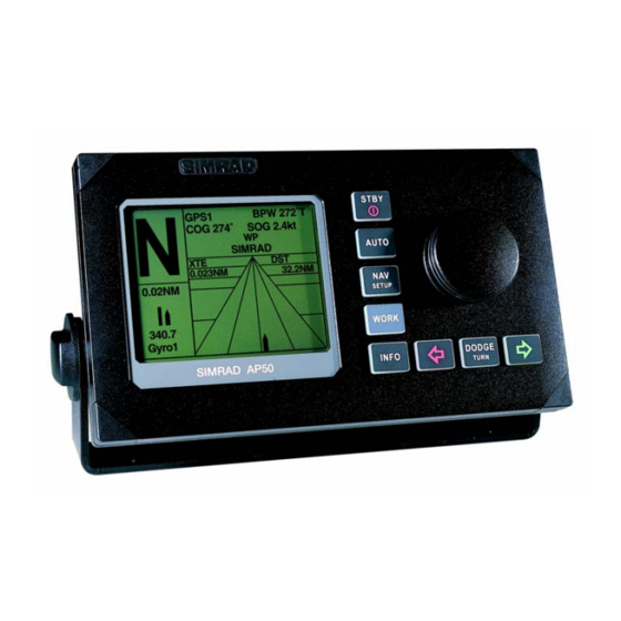
- Page 1 INSTRUCTION MANUAL Simrad AP50 Autopilot...
- Page 2 Note! Simrad AS makes every effort to ensure that the information contained within this document is correct. However, our equipment is continuously being improved and updated, so we cannot assume liability for any errors which may occur. Warning! The equipment to which this manual applies must only be used for the purpose for which it was designed.
- Page 3 Simrad AP50 autopilot. Great care has been taken to simplify the set-up and operation of the AP50; however, an autopilot is a complex electronic system. It is affected by sea conditions, speed of the vessel, and vessel hull shape and size.
-
Page 4: Document History
Simrad AP50 Autopilot Document revisions Date Written by Checked by Approved by 03.06.02 18.06.03 Document history Rev. A Original Issue Rev. B Updated according to software revision V1R2. Minor corrections in text. RF14XU added. 20221032B... -
Page 5: Table Of Contents
RI35 Mk2 Rudder Angle Indicator...............18 NI300X NMEA Interface Unit ..............18 OPERATION OF THE AUTOPILOT ..............19 Overview ......................19 ON/OFF - Standby Mode (STBY) ...............22 AP50 with MSD50 Stern Drive unit.............24 Zero point setting..................24 Operation ......................24 Follow-Up (FU) Steering................25 Non-Follow-Up (NFU) Steering ..............25 S100 (NFU) Steering Lever................25... - Page 6 R3000X Remote Control (NFU) ..............26 S35 NFU Steering Lever ................26 Automatic Steering ..................27 AUTO Mode....................27 AUTO-WORK Mode ...................28 Thruster Steering ..................29 Navigating with the AP50 ................30 Route Navigation..................31 Electronic Chart System (ECS) ..............32 Selecting a Different Navigator ..............33 NAV-WORK Mode..................33 Dodging ......................34 Dodging in AUTO Mode................34...
- Page 7 3.24 NMEA Sentences ..................68 INSTALLATION ....................71 General......................71 Unpacking and Handling ................71 Installation Index ..................71 Determining System Configuration..............73 AP50 System Layout ..................73 RF300S Rudder Feedback Unit ..............74 RF45X Rudder Feedback Unit ..............76 Electrical Connection ...................77 Mechanical Alignment .................79 RF14XU Rudder Feedback Unit ..............80 Mechanical mounting ...................80...
- Page 8 Simrad AP50 Autopilot 4.10 Drive Unit Installation ..................89 Connecting a Reversible Pump..............91 Connecting a Hydraulic Linear Drive............92 Solenoids (externally powered, common positive)........92 Solenoids (externally powered, common negative).........93 Connecting Solenoid Valves ................92 Solenoids (not externally powered) ............93 4.11 Control Unit....................94 Panel-mounting.....................94 Optional Bracket mounting ................94...
- Page 9 General Information Master Operation ...................121 Boat Type....................121 Boat Length....................121 Drive Unit Voltage.................121 Rudder Feedback Calibration ..............122 Rudder Calibration.................123 Rudder Test....................124 Set Rudder Zero ..................125 Rudder Limit..................125 Rudder Deadband...................125 Thruster ....................126 Interface Set-up...................126 Sea Trial......................132 Compass Calibration................133 Compass Offset..................134 Set Thrust Direction, On/Off Thruster...........135 Thruster Calibration, Analog Thruster...........135 Thruster zero ..................135 Direction and Maximum Thrust STBD, Analog Thruster .....136...
- Page 10 Simrad AP50 Autopilot W Autotrim ....................148 Autotrim....................148 Course Adjust..................149 Compass difference................149 Off Heading lim ..................149 Drive engage ..................150 Drive type....................151 Drive out ....................151 Prop. gain ....................151 Seastate ....................151 Rudder....................151 Counter rudder ..................152 W Seastate ....................152 W Rudder....................152 W Count rudder ..................152 W Rudder limit ..................152...
- Page 11 General Information Control unit....................161 Junction Unit....................161 Rudder Feedback ..................161 Compass (RC25/RFC35R) .................161 Drive unit ....................161 Exchange of software program..............162 TROUBLESHOOTING ..................165 Warnings.....................165 SPARE PARTS LIST ..................171 GLOSSARY......................177 INDEX.........................181 20221032B...
- Page 12 Simrad AP50 Autopilot This page is intentionally left blank 20221032B...
-
Page 13: General Information
The system can be expanded and enhanced with a selection of options and accessories. The brain in the AP50 autopilot system is the single "intelligent" junction unit that communicates with all other system modules on a RobNet network. The RobNet has been developed to... -
Page 14: How To Use This Manual
“master unit” in order for the installation to be approved. Simrad has no responsibility for the incorrect installation or use of the AP50 autopilot, so it is essential for the person in charge of the installation to be familiar with the relevant requirements as well as with the contents of this manual, which covers correct installation and use. -
Page 15: System Components
The Warranty Card must be completed by the authorized dealer that performed the installation and mailed-in to activate the warranty. 1.3 System Components A basic AP50 system may consist of the following units (refer to Figure 1-1): • AP50 Control Unit with accessories • Heading Sensor •... -
Page 16: Ap50 Control Unit
It also has two RobNet connectors for system interconnection and expansion. 1.5 Junction Units The junction unit in the AP50 autopilot system contains the steering computer, interface circuits to all system components, and drive circuits for the drive unit motor and clutch. Two models, J50 and J50-40, are available. -
Page 17: Rf45X Rudder Feedback Unit
CD100A Course Detector and CDI35 Course Detector Interface The sensor and interface unit connects the AP50 system to a magnetic compass. The AP50 provides excitation current for CD100A and converts the analog sine/cosine signal to digital two-wire format for the autopilot steering computer. -
Page 18: Other Compass Models
A series of options are available for the AP50 system. AP51 Remote Control This portable remote control unit for AP50 with 7 m (23 ft.) of cable can be used as a hand-held remote control or can be mounted in a fixed bracket-mount. -
Page 19: S100 Nfu Steering Lever
TI50 Thruster Interface The TI50 Thruster Interface is designed to provide a control signal for operating a thruster in an AP50 system by either on/off solenoids, analog ±10V control, or Danfoss PVEM valve. The thruster output signal is calculated in the TI50 based on operational mode and heading information received over RobNet from other system units. -
Page 20: Ad50 Analog Drive
AD50 Analog Drive The AD50 Analog Drive is designed to provide a control signal for operating an analog rudder in an AP50 system by either analog or proportional ±10V control, or Danfoss PVEM valve. The analog rudder output signal is calculated in the AD50 based on operational mode and heading information received over RobNet from other system units. -
Page 21: Operation Of The Autopilot
Inactive RUDDER 340. SETUP Gyro1 WORK DODGE SIMRAD AP50 INFO TURN Figure 2-1 AP50 Front Panel Buttons Action Function Short press: Switches the system on. Selects STANDBY mode. Long press (3 sec.): Switches the system off. STBY Quick double press: Locks or unlocks other control units and levers in the system. - Page 22 Simrad AP50 Autopilot Buttons Action Function Single short press: Selects AUTO mode and sets the heading reference. AUTO Second short press Sets new heading reference. Short press: Selects NAV mode prompt screen from AUTO mode. Verifies new course to steer when alert screen is shown (can also use the course knob, see below).
- Page 23 Operation Buttons Action Function Press simultaneously Activates Follow-up steering mode. Rotate in Follow-up Sets commanded rudder angle. steering mode: Rotate in AUTO Counter clock-wise = Port course change mode: Clock-wise = Starboard course change Rotate in NAV Verifies new course to steer when alert screen is Course mode: shown.
-
Page 24: On/Off - Standby Mode (Stby)
A group of user-adjustable settings belonging to the selected mode are provided in the AP50 User Set-up Menu (see page 38). The settings allow adjustment of display visibility, selection of heading sensor, navigation and position sources, and the ability to select between automatically or manually adjustable sea state filter. - Page 25 Operation Junction unit model Simrad Software V(ersion) and R(elease) SW V1R2 P05 M00 S000 Power board revision, Main board revision and Self check (SW and HW revisions shown are examples only) After approximately 5 seconds, the system is operative and the unit that was turned on will show the STANDBY mode display.
-
Page 26: Ap50 With Msd50 Stern Drive Unit
Simrad AP50 Autopilot 2.3 AP50 with MSD50 Stern Drive unit Note ! The information in section 2.3 only applies if your autopilot is driving a Simrad MSD50 Stern Drive. The MSD50 Stern drive unit has a relative feedback signal which needs a zero point setting after the autopilot has been turned on. -
Page 27: Follow-Up (Fu) Steering
When both the (PORT) and (STBD) buttons are pressed simultaneously, the AP50 will enter Follow-Up steering mode and the course knob may be used to set rudder commands. One revolution of the knob equals a 45° rudder change. The rudder will move to the selected angle and stop. -
Page 28: R3000X Remote Control (Nfu)
Simrad AP50 Autopilot R3000X Remote Control (NFU) In STANDBY mode, the rudder will SIMRAD move as long as the Port or Stbd button is pressed. Push buttons for Port and Stbd NFU commands In AUTO mode the set course will change 1°... -
Page 29: Automatic Steering
AUTO automatically on a set heading. AUTO mode is always available from any mode or function within the AP50 by a single push of the AUTO button. When AUTO mode is selected, the AP50 automatically selects the current vessel heading as the set heading and the rudder will move to midship position. -
Page 30: Auto-Work Mode
Simrad AP50 Autopilot Press the STBY button to regain manual steering STBY AUTO-WORK Mode The AUTO-WORK mode is an automatic steering mode to be used under operational conditions different from those normally found when a vessel is in transit on a pre-set course. Examples are trawling, towing, trolling on one engine, slow speed etc. -
Page 31: Thruster Steering
2.7 Thruster Steering If the vessel is equipped with a thruster, it can be connected to the AP50 system and the vessel can then be controlled by rudder, thruster, or both rudder and thruster. After connecting a thruster to the autopilot system (see the TI50 manual) the thruster type must be selected under the Installation Dockside menu (see page 126). -
Page 32: Navigating With The Ap50
• At least one waypoint must be entered and selected as the current waypoint in the navigation receiver • The navigation source in the AP50 User Set-up menu must be set for the navigator that contains the current waypoint The AP50 is designed to steer in mixed mode operation. This... -
Page 33: Route Navigation
Route Navigation When operating the AP50 in NAV mode to automatically steer through a route of waypoints, the AP50 will steer to the first waypoint in the route after you accept the first waypoint as the location to steer towards. -
Page 34: Electronic Chart System (Ecs)
STBY button. Note ! If the AP50 is connected to a navigation receiver that does not transmit a message with the bearing to the next waypoint, it will pick a Cross Track Error message and steer on Cross Track Error only. In that case you have to revert to AUTO mode at each waypoint and manually change the set course to equal the bearing to the next waypoint and then select NAV mode again. -
Page 35: Selecting A Different Navigator
Caution ! If an ECS is selected as a navigator, the course change verification is waved. This is done so the AP50 is capable of following a route in which the radius of the course change is pre-set in the chart system. Users navigating in this mode must use extra caution. -
Page 36: Dodging
When in DODGE mode, the set course is displayed (for example, as A329 degrees) and this set course is remembered by DODGE the AP50. When DODGE is flashing on the display, the AP50 is RUDDER no longer in control of the steering and you must either steer the 340. -
Page 37: Dodging In Nav Mode
GPS1 DODGE .023 previous set course is stored by the AP50. When DODGE is flashing on the display, the AP50 is no longer in control of the NEXT WP 340. SIMRAD steering and you must either steer the boat manually or take °M... -
Page 38: Turn Mode
A long press of the (DODGE/TURN) button activates U- DODGE DODGE TUR N T URN Turn. The AP50 will continue on the set course until you press either U TURN (PORT) or (STBD) button to select the direction in PORT Press STBD which to make the U-turn. -
Page 39: Multiple Station System
Operation The AP50 will continue on the set course until you press either C TURN the PORT or STBD button to select the direction in which to 90 °/min Press make the C-turn. If you do not press PORT or STBD within 1... -
Page 40: Master Operation
Simrad AP50 Autopilot When the "LOCK" function is in use, no transfer of command may take place; only the "active" control unit stays in command. Note ! On a locked control unit, backlight and contrast can be directly adjusted through the course knob. -
Page 41: External System Selection
“Disengaged” on the display (no mode indicators are lit on the FU50). When automatic steering is selected, the AP50 will go to AUTO mode (or AUTO-WORK mode). For connection of an external system selector switch, refer to “System Select”, on page 87. - Page 42 AUTO mode and NAV mode the rudder is always selected. Speed (Man, Log, SOG) The AP50 adapts to the speed of the vessel and this setting should be adjusted accordingly. If a speed log or other speed source is not connected, the speed input can be set manually by the course knob with range from 1 to 70 Knots.
-
Page 43: Auto Mode
Operation AUTO Mode Backlight SETUP Move : Adjust : Same procedure as in STANDBY mode. Backlight Contrast Contrast 341° Steering function Rudder Seastate AUTO Same procedure as in STANDBY mode. Rudder 0.50 340.7 Count rudder 1.40 Gyro1 More Steering Function (only available if Thruster is selected in the Installation Dockside Menu, see page 126). - Page 44 Simrad AP50 Autopilot Rudder Rudder sets the rudder gain, which is the ratio between the commanded angle and the heading error (p-factor). The default value depends on the boat length. The value (ranging between 0.05 and 4.00) is determined during Sea trial (see page 140), but can easily be adjusted in the User Set-up menu.
-
Page 45: Auto-Work Mode
340.7 Gyro1 More Use the course knob to change value. These values are stored in the AP50 memory and are automatically recalled when returning to AUTO-WORK mode. Use the course knob to adjust the trim value, if needed. The SETUP... -
Page 46: Nav Mode
Simrad AP50 Autopilot NAV Mode The NAV mode will not work satisfactorily before AUTO mode SETUP Move : is set-up and working properly. Adjust : Backlight Contrast Backlight .12NM Steering function Rudder Seastate AUTO Same procedure as in STANDBY mode. -
Page 47: Nav-Work Mode
Selected values for Seastate filter, Rudder, and Counter Rudder are stored in the AP50 memory and are automatically recalled when returning to NAV-WORK mode. Use the course knob to adjust the trim value, if needed. The... -
Page 48: Instrument Screens And Menu
Simrad AP50 Autopilot 2.15 Instrument Screens and Menu A number of instrument screens are available under each mode screen if the required NMEA 0183 sentences are provided (see page 68). Activate the instrument screen by pressing the INFO (INFO) button. - Page 49 Operation GPS1 POSITION WIND DIRECTION TRUE WIND 27.209 N 58° 58.322 E 005° 274°T 046° 046° 12.40kt WP SIMRAD 272 °T 32.2 NM Stern 0.012 NM Nav Data Wind direction True wind WIND APPARENT THRUSTER 046° RUDDER RUDDER Stern Apparent wind...
-
Page 50: Screen Selection
Simrad AP50 Autopilot Screen Selection If you do not need all of the instrument screens to be present in the screen menu, you may temporarily remove screens by quickly double-pressing the (INFO) button. Move through INFO the screens by pressing the... -
Page 51: Technical Specifications
Technical Specifications 3 TECHNICAL SPECIFICATIONS 3.1 AP50 Autopilot System Boat size and type:................Up to 200 feet, power Steering system types: ........... Hydraulic, mechanical, solenoids Inter-unit connection: ........RobNet network or two-wire supply/data System ON/OFF: ..............From control units/master unit Supply voltage: ................12-32 VDC –10%/+30% Power consumption: .....Dependent on system configuration (See 3.4 Junction Unit) -
Page 52: Ap50 Control Unit
Type: ..................Backlit LCD matrix Resolution:..................160 x 128 pixels Illumination: ..................Adjustable in 10 grades Mounting: ............Panel mount or bracket mount (optional) Cable:..........RobNet cable 15 m (49 ft.) with one male connector Figure 3-1 AP50 Control Unit Dimensions 20221032B... -
Page 53: Ap51 Remote Control
Technical Specifications 3.3 AP51 Remote Control Dimensions: ....................See Figure 3-2 Weight: ....................0.57 kg (1.25 lbs.) Material:.........................PC-ABS Supply..............12-32 VDC –10%/+30% via RobNet Power consumption ......................3 W Environmental Protection:................... IP56 Safe distance to compass: ................0.35 m (1.0 ft.) Color: ......................... -
Page 54: Junction Units
Rudder feedback units: ................. RF300S or RF45X NMEA input/output ports:................... Two External Alarm: ........... Open collector 0.75A (automatic fused) Mounting: ....................Bulkhead-mount System selector Autopilot/Main steering system ......Potential free contact Heading output: .. Simrad and Furuno radar display (clock/data; 0-5V, 10mA, 50 msec.) 20221032B... -
Page 55: Rc25/Rfc35R Rate Compass
Technical Specifications Figure 3-3 J50 Junction Unit - Dimensions Figure 3-4 J50-40 Junction Unit Dimensions 3.5 RC25/RFC35R Rate Compass Dimensions: ....................See Figure 3-5 Weight: ...................... 0.9 kg (2.0 lbs.) Power consumption: ..................... 0.9 watts Supply and interface: ....................RobNet Environmental Protection:................... -
Page 56: Cdi35 Course Detector Interface
Simrad AP50 Autopilot Mounting: ................ Deck-mount or bulkhead-mount Cable:...............15 m (49 ft.) RobNet cable with connector Automatic Performance: Calibration: ..........Automatically activated by control head Rate sensor stabilized heading output Accuracy:..............<1.25° rms (after calibration) Repeatability: ...................<0.2° rms Roll/Pitch: .......................± 35°... -
Page 57: Cd100A Course Detector
Technical Specifications Cable:..............15 m (49 ft.) single twisted pair, shielded Automatic Performance: Calibration: ..........Automatically activated by control head Repeatability: ....................± 0.5° Accuracy:..± 1,0° after calibration (not including errors from course detector) 3.7 CD100A Course Detector Dimensions: ....................See Figure 3-6 Weight: ................0.3 kg (0.7 lbs.) including cable Environmental Protection:................... -
Page 58: Ri35 Mk2 Rudder Angle Indicator
Simrad AP50 Autopilot 3.9 RI35 Mk2 Rudder Angle Indicator Dimensions: ....................See Figure 3-7 Weight: ...................... 1.0 kg (2.2 lbs.) Material:..................Epoxy coated aluminum Supply voltage: .........12-24 VDC –10%/+30%, polarity independent Power consumption: .....................Max 3 W Environmental Protection:................... IP56 Safe distance to magnetic compass: ..............0.3 m (1 ft.) Temperature range: Operation: ............ -
Page 59: Rf300S Rudder Feedback Unit
Technical Specifications 3.10 RF300S Rudder Feedback Unit Dimensions: ................ See Figure 3-8 and Figure 4-2 Weight: ...................... 0.5 kg (1.1 lbs.) Material: .....................Arnite T06 200 PBT Environmental Protection:................... IP56 Temperature range: Operation: ............... –25 to +55°C (–13 to +130°F) Storage: ..............–30 to +80°C (–22 to + 176°F) Mounting: ..............Horizontal, vertical, or upside down Cable:.............. -
Page 60: Rf45X Rudder Feedback Unit
Simrad AP50 Autopilot 3.11 RF45X Rudder Feedback Unit Dimensions: ...........See Figure 3-9, Figure 3-11 and Figure 4-4 Weight: ...................... 1,0 kg (2,2 lbs.) Material: ....................Polyacetal (POM) Supply voltage: ..........12-24 VDC –10%/+30%, system supplied Environmental Protection:................... IP56 Temperature range: Operation: ............... –25 to +55°C (–13 to +130°F) Storage: .............. -
Page 61: Rf14Xu Rudder Feedback Unit
Technical Specifications 3.12 RF14XU Rudder Feedback Unit Dimensions: ....................See Figure 3-10 Weight: ...................... 2,8 kg (4,9 lbs.) Material:................Reinforced glass fibre polyester Environmental Protection: ..................IP56 Ambient temperature: ..................–10 - +55°C Supply voltage: ................. 24VDC –10%/+20% Voltage output: ................Operating voltage/2 ±9V Frequency output: .............. -
Page 62: Gi50 Gyro Interface
Simrad AP50 Autopilot Figure 3-11 RF Standard Transmission Link - dimensions 3.13 GI50 Gyro Interface Dimensions: ....................See Figure 3-12 Weight: ...................... 0.7 kg (1.5 lbs.) Material:..................Epoxy coated aluminum Environmental Protection:................... IP44 Supply voltage: ...................... 12 VDC Power consumption: ....................2.4 W Load:....................... -
Page 63: Ci300X Compass Interface
Technical Specifications Figure 3-12 GI50 Gyro Interface Dimensions 3.14 CI300X Compass Interface Dimensions: ....................See Figure 3-13 Weight: ...................... 0.9 kg (2.0 lbs.) Material:..................Epoxy-coated aluminum Environmental Protection:................... IP44 Supply and interface .................RobNet, 2 connectors Power consumption: .....................2 W Safe distance to magnetic compass: ..............0.3 m (1 ft.) Temperature range: Operation: .............. -
Page 64: Ni300X Nmea Interface
Mounting: ....................Bulkhead mount Cable inlets: ..........Rubber glands for cable diameter 10-14 mm NMEA183 input/output:..........4 ports, max. output load 20 mA Heading output: ..Simrad (Anritsu) and Furuno radar display (clock/data; 0-5V, 10mA, 50 msec.) NMEA instrument supply:..............12 VDC, max 0.25A External alarm: ..................Potential free contact... -
Page 65: Ti50 Thruster Interface
Technical Specifications 3.16 TI50 Thruster Interface Dimensions: ....................See Figure 3-13 Weight: ....................... 0,8 kg (1.8 lbs) Material:..................Epoxy coated aluminium Environmental Protection: ..................IP44 Supply and interface: ................RobNet, 2 connectors Cable inlets: ............Rubber glands for cable diam. 10-14 mm Mounting: .................... -
Page 66: R3000X Remote Control
Simrad AP50 Autopilot Rudder drive interface: Danfoss PVEM:....Nominal U =12/24V, I=0.25/0.5mA, neutral 0.5*Un, control range 0.25*U to 0.75*U valve saturated for<0.25*U or >0.75*U Analog control, internal supply: ...Control range±10V, max. 5 mA, galvanic isolated Analog control, external supply: ....U 12-24VDC, control range 0- U ±U... -
Page 67: S100 Nfu Steering Lever
Technical Specifications 3.19 S100 NFU Steering Lever Dimensions: ........See Figure 3-15 Weight:..........0.5 kg (1.1 lbs.) Environmental Protection: .... Not for outdoor use Safe distance to compass: .....0.15 m (0.5 ft.) Temperature range: Operation:....–25 to +55°C (–13 to +130°F) Storage: .... -
Page 68: F1/2 Remote Control
Simrad AP50 Autopilot Figure 3-16 S35 NFU Steering Lever Dimensions 3.21 F1/2 Remote Control 76 (3.0") 65 (2.6") Dimensions:...... See Figure 3-17 Weight: ....1.2 kg (2.6 lbs.) incl. cable Material: ....... Painted aluminum Environmental Protection:....IP56 Safe distance to compass:..0.1 m (0.3 ft.) Max. -
Page 69: Fu50 Steering Lever
Technical Specifications 3.22 FU50 Steering Lever Dimensions: ....................See Figure 3-18 Handle can be mounted pointing upwards or downwards. Weight: ................1.2 kg (2.6 lbs.) including cable Material:....................Polyacetal (POM) Environmental Protection:................... IP56 Power consumption: .....................3W Safe distance to compass: ................0.15 m (0.5 ft.) Temperature: Operating: ............... -
Page 70: Environmental Protection
Simrad AP50 Autopilot 3.23 Environmental Protection Each part of a Simrad autopilot system has a two-digit IP protection code. The IP rating is a method to classify the degree of protection against solid objects, water ingress, and impact afforded by electrical equipment and enclosures. - Page 71 No data action AP50 system, NMEA 183 messages (applies for J50 and NI300X sw release V1R2 onwards) delay (sec) Sentence Formatter mnemonic code Bold = recommended navigator/instr. output for autopilot Remarks: * = IMO designated ( ) = not for new designs...
- Page 72 Simrad AP50 Autopilot This page is intentionally left blank 20221032B...
-
Page 73: Installation
A visual inspection should be made to ensure that the equipment has not been damaged during shipment and that all parts are present according to the packing list. A standard scope of supply for a basic AP50 system may include: • A control unit with standard installation accessories •... - Page 74 Simrad AP50 Autopilot 4. Set the language (see page 120) 5. Select the dockside settings and perform tests (see page 119) a) Master operation b) Boat type selection c) Boat length selection d) Drive unit voltage selection. e) Rudder calibration...
-
Page 75: Determining System Configuration
4.4 Determining System Configuration It is important to become familiar with the configuration of the system prior to beginning the installation. The AP50 Basic system is shown in Figure 1-1 on page 13 and an extended system is shown in Figure 4-1 on page 73. -
Page 76: Rf300S Rudder Feedback Unit
Simrad AP50 Autopilot 4.6 RF300S Rudder Feedback Unit (For small to medium size vessels) The RF300S Rudder feedback unit mounts close to the rudders, and is mechanically linked to the rudder tiller arm or rudder quadrant (refer to Figure 4-2 on page 75 for the recommended mounting arrangement). -
Page 77: Junction Unit
Installation Figure 4-2 RF300S Rudder Feedback Unit Mounting (019356) Note ! Due to space limitations, it may be necessary to cut the length of the transmitter rod to move the RF300S closer to the rudderpost. Tighten the mounting screws for both the RF300S Rudder Feedback Unit and the transmitter rod ball joint. -
Page 78: Rf45X Rudder Feedback Unit
However, it can be mounted with the shaft pointing downwards for increased convenience. The deflection can then be inverted in the AP50 software or as illustrated in Figure 4-5 on page 77. An “upside-down” installation will make access to the unit more efficient as it can be opened without moving it from the mounting base. -
Page 79: Electrical Connection
Installation Electrical Connection Use a twisted-pair shielded cable, 0.5 mm (AWG20), between the breakout box and the J50 Junction Unit. The cable length is not critical but should be kept to a minimum. The cable should be connected to the junction unit according to Figure 4-5. -
Page 80: Rudder Angle
Simrad AP50 Autopilot Figure 4-6 RF45X Connection to RI9 Rudder Angle Indicators and RI35 Mk2 (optional) The above connection diagram shows how to connect an RI9 Rudder Angle Indicator to a system with RF45X Rudder Feedback Unit. For connection of RI35 Mk2 Rudder Angle Indicators only, refer to the RI35 Mk2 manual. -
Page 81: Mechanical Alignment
Installation Mechanical Alignment The purpose of this procedure is to find the zero point and to allow the feedback unit to operate within its active segment. If the unit operates outside this segment, there will be a feedback failure alarm. 1. -
Page 82: Rf14Xu Rudder Feedback Unit
Simrad AP50 Autopilot 4.8 RF14XU Rudder Feedback Unit Mechanical mounting Before installation check that the alignment mark on the mounting plate agrees with the mark on the shaft. Bring the rudder to Midships position. The feedback unit should be mounted on a plane surface and secured by bolts through the three holes in the mounting plate. - Page 83 Installation The feedback unit has an external ground terminal an must have a proper ground connection to the hull. The grounding wire should be as short as possible and at least 10 mm wide. The RF14XU can be powered either from the rudder angle indicator supply (19-40V DC) or directly from the autopilot junction unit.
- Page 84 10, for +/-90˚ connect violet lead to terminal 10. White lead must remain connected. Figure 4-9 RF14XU Internal wiring Figure 4-10 shows how to connect the RF14XU Rudder Feedback Unit to an AP50 system with 24V autopilot supply. 20221032B...
- Page 85 J50 Vbat+ instead of J50 Supply+. Note ! This configuration is only for 24VDC. Figure 4-10 RF14XU connected to an AP50 system and optional rudder angle indicators Note ! The resistor R (0.5-1K, 0.5W) has to be mounted. The resistor is not supplied by Simrad.
-
Page 86: Final Check
Simrad AP50 Autopilot Final check After installation, the cable glands must be sealed with silicon to prevent water from seeping in. Also apply silicon grease to the gasket between the bottom and top cover. On the inside of the feedback unit cover, a piece of moisture protecting sponge is attached. -
Page 87: J50 Junction Unit
Installation 4.9 J50 Junction Unit The J50 Junction Unit is designed to operate in a location that provides ambient temperatures below +55°C (+130°F). Note ! The junction units (J50 and J50-40) are not waterproof and should be mounted vertically, as shown in Figure 4-11, in a dry place between the control unit and the drive unit. -
Page 88: Grounding And Radio Frequency Interface (Rfi)
Simrad AP50 Autopilot Grounding and Radio Frequency Interface (RFI) The AP50 system has excellent radio frequency interference protection and all units use the junction unit as a common ground/shield connection. The junction unit must therefore have a proper ground connection to the hull. -
Page 89: System Select
Installation J50-40 Power Board Terminals Main Board Terminals System Select The “System select” (Sys. Sel.) input signal of the J50 can be used to alternate between the boat’s own steering and the autopilot system from an external system selector (refer to IMO resolution MSC. -
Page 90: External Alarm (Non Wheelmark System)
Note ! Wheelmark installation requires separate monitoring of power failure. Note that Simrad does not supply an external alarm unit, required for a Wheelmark system. The diagram below shows how an arrangement can be made. The buzzer shall provide between 75 and 85 dB of power. -
Page 91: Drive Unit Installation
The relation between drive units, drive unit voltage, input voltage, drive output, and interfacing to steering gear are shown in Table 4-2 and Table 4-3. The AP50 system detects whether a reversible motor or a solenoid is connected and outputs the correct drive signal automatically. - Page 92 Simrad AP50 Autopilot LINEAR DRIVE UNITS MODEL MOTOR JUNCTION MAX. PEAK MAX. HARD- PWR. TILLER VOLTS UNIT STROKE THRUST RUDDER OVER CON- mm (in.) kg (lb.) TORQUE TIME SUMP. sec. (in.) (lb./in.) (30% load) MLD200 300 (11.8) 1.5-6 A (440) (4350) (10.4)
-
Page 93: Connecting A Reversible Pump
Installation PREVIOUS MODELS Simrad Drive Input Drive output Interface to Drive Unit type unit voltage steering gear voltage (Mains) RPU100, 12, 24,32 Proportional Hydraulic RPU150, rate plumbing (Reversible hydraulic pump) MRD100 12, 24, 32 12V to clutch Chain/ (Reversible 24, 32... -
Page 94: Connecting A Hydraulic Linear Drive
Simrad AP50 Autopilot Connecting a Hydraulic Linear Drive HYDRAULIC JUNCTION UNIT LINEAR DRIVE POWER PCB Drive engage Single pole clutch/bypass switch Figure 4-16 Connecting a Hydraulic Linear Drive Connecting Solenoid Valves Solenoids (externally powered, common positive) JUNCTION UNIT POWER PCB... -
Page 95: Solenoids (Externally Powered, Common Negative)
Installation Solenoids (externally powered, common negative) JUNCTION UNIT POWER PCB SOLENOID VALVE Solenoid isolated Figure 4-18 Connecting Externally-powered Solenoids with a Common Negative Caution ! To prevent damage of the J50 Power PCB, ensure that the S1 jumper switch on the Power PCB is set to position 2-3. Solenoids (not externally powered) JUNCTION UNIT SOLENOID... -
Page 96: Control Unit
• Connect the RobNet cable(s) to the control unit connector(s) (see “Note!” on page 97). Optional Bracket mounting (This may be ordered separately from Simrad, part no. 20212130). Note ! When the control unit is bracket-mounted, it is not weatherproof from the back due to a breathing hole in the back cabinet. -
Page 97: Robnet Network Cables
Additional extension cable (10 m) with a male and a female connector, is available from Simrad (part no. 22192266). When installing a system, try to minimize the total RobNet cable length by connecting all RobNet units to the nearest available RobNet connector. - Page 98 55 (180’) 50 (165’) 45 (150’) 40 (130’) If the total length exceeds the recommended length, please contact your Simrad distributor on how to arrange the system to minimize the voltage drop. Examples of interconnecting RobNet units: CONTROL CONTROL CONTROL...
- Page 99 Green ALARM Table 4-5 RobNet Plug Pin Configuration AP50 JUNCTION UNIT CONTROL MAIN PCB UNIT Pnk Gry Yel ROBNET Figure 4-23 Control Unit Connection Note ! For installations that require special cable lengths, contact your Simrad distributor for information. 20221032B...
-
Page 100: Ap51 Remote Control Connection
Simrad AP50 Autopilot AP51 Remote Control Connection If the AP51 Remote Control is part of the system, use the RobNet connector in a free receptacle (see Figure 4-21). Alternatively, cut the connector from the cable and connect the wires in parallel with the cable shown on Figure 4-23 using the same color code. -
Page 101: Rc25/Rfc35R Rate Compass
4.12 RC25/RFC35R Rate Compass Figure 4-25 RC25/RFC35R Rate Compass Mounting The heading sensor is the most important part of the AP50 system and great care must be taken in choosing the mounting location. The heading sensor can be mounted at any location where there is a minimum of magnetic interference and minimum movements. - Page 102 UNIT Figure 4-26 RC25/RFC35R Connection to AP50 Control Unit • Connect the RobNet connector to the AP50 Control Unit (or CI300X or NI300X if installed). • Alternatively, if there is no free receptacle, cut the connector from the cable and connect the wires in parallel with the wires going from the junction unit to the control unit.
- Page 103 Installation JUNCTION UNIT RATE COMPASS NMEA ROBNET EXT.COMP JUNCTION UNIT MAIN PCB TB15 RFC35R RATE Bn Wht COMPASS RATE PCB Robnet JUNCTION UNIT MAIN PCB TB15 GREY PINK BROWN WHITE Bn Wht Robnet RC25 RATE COMPASS Figure 4-27 Alternative Connection to J50 Junction Unit RobNet Terminal •...
-
Page 104: Rfc35 Fluxgate Compass
4.14 TI50 Thruster Interface The TI50 Thruster Interface is designed to provide control signal for operating one thruster in an AP50 system by either on/off solenoid, continuous control, or Danfoss PVEM valve. Refer to separate manual for the TI50 Thruster Interface. -
Page 105: R3000X Remote Control
Installation 4.16 R3000X Remote Control The R3000X Remote Control is weather proof and can be mounted outdoors in the supplied bracket that is fixed by four mounting screws. JUNCTION UNIT R3000X POWER PCB REMOTE CONTROL G n R ed Blu R EM O TE R E M O T E Figure 4-29 R3000X Remote Control Connection... -
Page 106: S35 Nfu Steering Lever
Simrad AP50 Autopilot 4.18 S35 NFU Steering Lever The S35 NFU Steering Lever may be mounted to the bulkhead or to a panel by two screws from the front. The cable is connected to the junction unit according to Figure 4-31. If... -
Page 107: Interfacing To Optional Equipment (Thd, Navigation Receiver, Etc.)
Installation 4.20 Interfacing to Optional Equipment (THD, Navigation Receiver, etc.) With the AP50 autopilot system, there are several options for connection to other equipment for data exchange: 1. The J50 Junction Unit includes two NMEA input/output ports and a Clock Data heading interface to Simrad and Furuno radars. -
Page 108: Double Nmea Input/Output
Simrad AP50 Autopilot Double NMEA input/output JUNCTION UNIT MAIN PCB POWER PCB GPS or ECS TB13 TB14 NMEA NMEA GPS/PLOTTER NMEA NMEA NMEA Input 1 COMPASS Output1 Input2 Output2 Figure 4-34 Double NMEA Connection Output signal Output terminal Output sentence... -
Page 109: Radar Clock/Data
Installation Radar Clock/Data JUNCTION UNIT RADAR P O W E R P C B T B 6 T B 7 T B 8 R a d a r Figure 4-36 Radar Clock/Data Connections Analog Heading Repeater Figure 4-37 AR77 and AR68 Analog Heading Repeater Connections 20221032B... -
Page 110: Digital Heading Repeater
Simrad AP50 Autopilot Digital Heading Repeater Figure 4-38 DR75 Digital Heading Repeater Connections 20221032B... -
Page 111: Gi50 Gyro Interface
GI50 Gyro Interface The GI50 Gyro Interface is required when a gyrocompass with geared synchro or stepper signal output is connected to the AP50. The GI50 is also required when a speed log signal with 200 pulses/NM is connected to the system. - Page 112 Simrad AP50 Autopilot The potentiometer VR1 is factory set to a reference voltage of 2.5V, and should not be readjusted. Power Turn-on After power turn-on, verify that the LED D8 is lit. This indicates that the regulated 5V is OK.
-
Page 113: Ni300X Nmea Interface Unit
+55°C (+130°F). It is fastened to the panel/bulkhead by the external mounting brackets. Note ! The NI300X is not weatherproof and must be installed in a dry location! ALARM OUTPUT (Normally open) Clk C Clk H SIMRAD FURUNO N.C. RADAR DISPLAY DataC DataH TB11 IS15 INSTRUMENTS TB11... -
Page 114: Ci300X Compass Interface Unit
The CI300X Compass Interface Unit is an optional module designed to enable a variety of different equipment to connect into AP50 systems. The CI300X converts the analog inputs into RobNet compatible signals for use by AP50 system components. The CI300X adds the following capabilities to the AP50 system and allows connection of each of the following simultaneously: •... - Page 115 Figure 4-42 CI300X Compass Interface Unit Connections Note ! The CD100 is a previous model and its cable has a connector that must be cut off for connection in the AP50 system (e.g. to the CI300X or the CDI35). 20221032B...
-
Page 116: Cd100A Course Detector
Simrad AP50 Autopilot CD109 Course Detector For retrofit installations a CD109 Course detector may be connected to the CI300X according to Figure 4-43: PLUG MAGNETIC COMPASS Vref WITH CD109 COURSE DETECTOR Vref Figure 4-43 CD109 connections to CI300X CD100A Course Detector The owner may prefer to use the boat’s own compass. -
Page 117: Cdi35 Interface
Figure 4-45 CDI35 Interface Connections Note ! The CD100 is a previous model and its cable has a connector that must be cut off for connection in the AP50 system (e.g. to the CI300X or the CDI35). CD109 Course Detector For retrofit installations, a CD109 Course detector may be connected to the CDI35 according to Figure 4-46. - Page 118 Simrad AP50 Autopilot This page is intentionally left blank 20221032B...
-
Page 119: Software Set-Up Procedure
Some important points regarding the Installation Set-up values: • When the AP50 is delivered new from the factory, (AND ANY TIME AFTER A MASTER RESET OF MEMORIES SETUP REQUIRED... -
Page 120: Installation Menu
Simrad AP50 Autopilot stored in the memory of the AP50 system. No specific action is required to save the selected values to memory. Once the value is changed, it is stored until the next time the menu item is selected and changed. -
Page 121: Language Selection
NAV buttons. On new installations, and whenever a junction unit or software is replaced in an AP50 system, it is recommended that a Master Reset be performed as described under SERVICE in the Installation Menu (see page 147) prior to proceeding with the set-up procedure. - Page 122 Simrad AP50 Autopilot ENTER INSTALLATION MENU SYMBOLS INSTALLATION BY PRESSING AND HOLDING THE MENU NAV BUTTON FOR 5 SECONDS SELECT OR CONFIRM BY ROTARY COURSE SELECTOR PROCEED TO NEXT MENU ITEM LANGUAGE MENU BY PRESSING STBD BUTTON LANGUAGE ENGLISH DEUTSCH...
-
Page 123: 20221032B
Software Set-up Procedure Master Operation For vessel that comply with the European Marine Equipment directive, one control unit must be set for Master operation, if more than one control unit is connected. The other unit(s) is then automatically set as a “slave”. The system can only be switched DOCKSIDE off from the master unit (see also page 37). -
Page 124: Rudder Feedback Calibration
The clutch/bypass voltage is automatically set to coincide with the drive unit voltage. During the rudder test, the AP50 system will also automatically detect whether the drive unit is a reversible motor or whether it is solenoid operated. To change the voltage selection, rotate the course knob. -
Page 125: Rudder Calibration
Note ! If no adjustment has been made to the display readout (i.e. not turning the course knob), the AP50 will set the physical stop to 45°. “Max. rudder limit” will be set to 2° less. Note ! Rudder-zero may still be inaccurate and should be adjusted later during sea trial. -
Page 126: Rudder Test
DOCKSIDE clockwise. Rudder test ---- --------- drive Clutch --- -------- The AP50 will, after a few seconds, issue a series of PORT and Rudder limit Rudder deadband STBD rudder commands, automatically verify correct rudder Thruster ---- direction, detects minimum voltage for running, and reduce the rudder speed (reversing pumpset or proportional valves) if it exceeds the maximum acceptable speed for autopilot operation. -
Page 127: Set Rudder Zero
Software Set-up Procedure Set Rudder Zero This setting is only shown when analog rudder is used for DOCKSIDE steering. No value is shown before you start turning the course Set rudder zero knob. When activated, the AD50 will take control over the Rudder limit 10°... -
Page 128: Thruster
Thruster direction and the Maximum thrust. Interface Set-up The AP50 system provides a flexible approach to the input of data from heading sensors and other external equipment. Identification of the type of equipment connected to the AP50 system is performed in the Interface Menu. - Page 129 1 to 5 times/sec. on TX1 port. or VDR data HDT and RSA 5x/sec. Output RADAR Clock/data heading output to May select Simrad, Furuno, or radars Special** (for both J50 and NI300X) Automatic course change at waypoint will now occur during navigation in NAV mode.
- Page 130 Simrad AP50 Autopilot The Interface Set-up Menu presents names so that they can be assigned to the hardware input or output port (see Table 5-1 on page 127. Each abbreviated name is then presented in the appropriate locations of the User Set-up Menu (see page 39) to provide the user with choices of data sources.
- Page 131 Software Set-up Procedure Interface Set-up - Input Signal Set-up item Equipment Connected to terminal Assign hardware (abbrev. name) connected (name) (use one available from list) port to set-up item (* = default setting) GPS1 Not connected – – – – J50, Main PCB NMEA I/P RX1+,RX1–...
- Page 132 Simrad AP50 Autopilot Set-up item Equipment Connected to terminal Assign hardware (abbrev. name) connected (use one available from list) port to set-up item (name) (* = default setting) GYRO2 Not connected – – – – * Connection to RobNet ROBNET ** J50, Power PCB NMEA I/P RX2+,RX2–...
- Page 133 Software Set-up Procedure Set-up item Equipment Connected to terminal Assign hardware (abbrev. name) connected (use one available from list) port to set-up item (name) (* = default setting) FLUX1 Not connected – – – – RFC35R Connection to RobNet ROBNET* Junction unit: HS+, HS–...
-
Page 134: Sea Trial
• Compass Offset (to offset the final compass heading readout) • Max/Minimum thrust, thrust direction and levels (only if thruster is selected) • Set cruising speed (in the AP50) • Set rudder zero (to indicate the precise midships position of the rudder) •... -
Page 135: Compass Calibration
June 26 2003 Compass Calibration This function will activate the automatic compass calibration procedure (for Simrad compasses connected through RobNet and through J50 Junction Unit Heading Sensor (HS) terminal, and compasses connected through CI300X). Note ! If an optional magnetic compass is installed and connected to J50 or CI300X, or if a gyrocompass, or other manufacturer’s... -
Page 136: Compass Offset
(STBY) button. S TB Y Note ! If an optional NMEA compass from Simrad or another manufacturer is installed, refer to the optional compass’ manual regarding calibration. Compass Offset The compass Offset feature allows you to correct for a constant compass heading offset. -
Page 137: Set Thrust Direction, On/Off Thruster
Software Set-up Procedure Set Thrust Direction, On/Off Thruster (ONLY IF ON/OFF THRUSTER IS SELECTED, proceed to page 136 if continuous thruster or Danfoss thruster is selected) Rotate the course knob clockwise to activate the Set thrust SEATRIAL direction setting. Compass Flux1 Calibration Offset... -
Page 138: Direction And Maximum Thrust Stbd, Analog Thruster
Simrad AP50 Autopilot Direction and Maximum Thrust STBD, Analog Thruster (ONLY CONTINUOUS THRUSTER DANFOSS SEATRIAL THRUSTER IS SELECTED) Thruster zero Maximum thrust STBD ---% Maximum thrust PORT ---% Rotate the course knob clockwise to activate the Maximum Minimum thrust thrust STBD setting. -
Page 139: Minimum Thrust, Analog Thruster
Software Set-up Procedure Minimum Thrust, Analog Thruster (ONLY CONTINUOUS THRUSTER DANFOSS THRUSTER IS SELECTED) The Minimum thrust determines the amount of power (in % of SEATRIAL Thruster zero the maximum control signal) that is applied as the "first Maximum thrust STBD 080% Maximum thrust PORT 079% command signal". -
Page 140: Set Cruising Speed
Simrad AP50 Autopilot Set Cruising Speed Steer the boat at cruising speed. The speed is shown at the Set SEATRIAL cruising speed line. Rotate the course knob clockwise to Compass Flux1 Calibration confirm the cruising speed. Offset +005° Heading 288°... -
Page 141: Adjust Rudder Angle/Set Rate Of Turn
Software Set-up Procedure automatic modes (Ref. User Set-up, page 39). The Turn gain may also be readjusted (Refer to Turn Gain on page 155). Note ! The Set rate of turn function is only activated when using the course knob, NOT the Port and STBD buttons. Proceed to the next function by pressing the (STBD) button. -
Page 142: Manual Tuning
Run the boat at cruising speed. Rotate the course knob clockwise to activate the Manual Tuning. The AP50 will now control the steering of the boat. If another course is desired, rotate the course knob until the desired course is obtained. After the course has stabilized, observe the steering performance. -
Page 143: Automatic Tuning
Software Set-up Procedure While at cruising speed, adjust the Rudder value by turning the course knob until the autopilot keeps the boat on a steady course. Counter Rudder Press the (STBD) button to display the set course. Make a 90° SEATRIAL ADJUST course change (CTS) by rotating the course knob and observe... - Page 144 Simrad AP50 Autopilot Selecting the boat type and length has set default values for these parameters (Installation Dockside menu). Before doing any parameter tuning, check if the boat steers satisfactory with the default setting (can be checked as described under Manual Tuning or by normal Auto steering).
-
Page 145: Speed Response
Automatic tuning Speed response From the Sea trial menu, select Speed response by rotating the course knob clockwise. The AP50 will now take control over the SEATRIAL ADJUST steering of the boat. If another course is desired (CTS), rotate the course knob until 340 . -
Page 146: Providing User Training
• Set waypoints into each navigator connected to the system, and verify that the AP50 steers in NAV mode for each Nav. source. • Provide user training. -
Page 147: Advanced Settings
Select "SERVICE" by pressing the (STBD) button and confirm by rotating the course knob clockwise. “SYSTEM DATA” and “NMEA DATA” are test functions to analyze data processed by the AP50. SYSTEM DATA NMEA DATA NMEA PORT TEST To exit the menu, press any mode key (STBY, AUTO or NAV). -
Page 148: Nmea Data
---m Decoding The incoming signals are decoded according to a built-in priority table in the AP50. Cross Track Error and bearing information is taken from the NMEA messages with highest priority. For all data items, one of the following codes will be displayed: No data or no NMEA sentence containing the data needed at the input port. -
Page 149: Nmea Port Test (J50 Hardware)
NMEA PORT TEST knob clockwise and then rotate the course knob counter- Turn CCW Warning: clockwise. Will restore factory settings. New setup will be required Exit the Installation Menu by pressing the STBY (STBY) button to return to normal AP50 operation. 20221032B... -
Page 150: Settings Menu
Simrad AP50 Autopilot 6.2 Settings Menu Select SETTINGS in the Installation Menu by pressing the SETTINGS (STBD) button and confirm this by rotating the course knob STEERING clockwise. THRUSTER Two groups of settings are available; Steering and Thruster (only when thruster is installed). -
Page 151: Course Adjust
Advanced Settings The Autotrim parameter is reset every time the AUTO mode is entered or when a course change greater than approximately 20° is made by the course knob. Autotrim is automatically disabled during a turn. Course Adjust When using the (PORT) or (STBD) buttons in AUTO mode, you are changing the set course in 1°... -
Page 152: Drive Engage
Simrad AP50 Autopilot Drive engage This determines the use of the J50 Drive Engage port. The port voltage is the same as the selected Drive Unit voltage. Drive engage has the following different settings: Bypass/clutch: This port will activate (go high), in all modes except for STANDBY and DODGE hand-steering. -
Page 153: Drive Type
Advanced Settings Drive type This indicates the type of drive installed. The display will show “Motor”, “Solenoid”, “Proportional” or “Analog”, respectively. The reading is obtained from the Automatic rudder test under the Dockside menu. The set value may be changed here. Drive out Not applicable for “Analog”... -
Page 154: Counter Rudder
Simrad AP50 Autopilot Counter rudder Counter Rudder is the parameter that counteracts for the effect of the boats turn rate and inertia. The default value depends on boat length. Range: 0.05 to 8.00. W Seastate As for Seastate above but applies for the Work-modes. -
Page 155: Transition Speed
Planing boats may often have very different steering characteristics before and after planing. The same may apply for water jet driven boats at low and high speed. AP50 offers the possibility of using the Auto-Work mode values for Rudder and Counter Rudder at low speed. -
Page 156: Turn Mode
Simrad AP50 Autopilot Minimum Rudder 4.0° Rudder deadband 0.3° P-factor/Counter Rudder 1.0° Total rudder amount 5.3° Range: 0 to 10° in 0.1° increments Default: 0° Turn mode This allows for the selection of Rate of Turn (ROT) steering or Radius (RAD) steering. -
Page 157: Init Nav
Advanced Settings Default: 0 seconds. Init NAV Sets a firm or soft approach to the rhumb line when entering the NAV mode at the first leg. The approach angle is dependant (adaptive) on the distance (XTE) from the rhumb line and the boat speed. -
Page 158: Thruster
Simrad AP50 Autopilot Thruster Select Thruster in the Settings menu by pressing the (STBD) SETTINGS button and confirm this by rotating the course knob clockwise STEERING (only available when Thruster is selected for steering). THRUSTER Thruster inhibit Thruster inhibit is a feature that will block the thruster from... -
Page 159: Minimum Thrust
Advanced Settings When operating in “Continuous” mode, the thruster gain setting determines the power from the thruster versus heading error. For higher values, the power increases with the same error signal. If the vessel tends to oscillate around set heading, the value should be decreased. -
Page 160: Thruster Hyst
Simrad AP50 Autopilot Thruster hyst (Only applicable for Continuous and Danfoss thrusters) When applying a command signal to a proportional valve, a certain amount of deadband may occur, dependant on the directional change of the command. Therefore, a certain “extra”... - Page 161 Advanced Settings SETTINGS Displayed parameter Boat type (Default settings) Own boat Dockside Menu Displacement Planing Waterjet Autotune Manual Master Operation Boat length 0-50 feet 0-50 feet 0-50 feet Drive unit voltage Rudder limit 10° 10° 10° Rudder deadband AUTO AUTO AUTO Thruster - - - -...
- Page 162 Simrad AP50 Autopilot This page is intentionally left blank 20221032B...
-
Page 163: Maintenance
Maintenance 7 MAINTENANCE 7.1 Control unit Under normal use, the AP50 Control Unit will require little maintenance. The case is made from seawater resistant aluminum and it has a polyester coating to withstand the rigorous conditions of an exposed cockpit. It is recommended that units kept clean of salt, since salt will corrode metal over time. -
Page 164: Exchange Of Software Program
Simrad AP50 Autopilot 7.6 Exchange of software program Junction Unit PROM Figure 7-1 J50/J50-40 Main PCB, Component Layout AP50 Control Unit PROM Figure 7-2 AP50 PCB, Component Layout 20221032B... - Page 165 - the Simrad part number - the software version Caution ! Make sure that the correct PROM is mounted in each unit: PROM for the AP50 Control Unit: P/N 20212189 PROM for the J50 and J50-40 Junction units: P/N 20211934 •...
- Page 166 Simrad AP50 Autopilot This page is intentionally left blank. 20221032B...
-
Page 167: Troubleshooting
An autopilot is a complex system. Its performance dependents on a proper installation and a successful sea trial. In the event of an autopilot failure, the AP50’s numerous test features that will assist you in isolating a probable fault. Audible and visual alarm is provided for every fault being detected. - Page 168 Simrad AP50 Autopilot Display readout Probable fault Recommended action − Steering gear not No rudder response 1. Check all connections. operative (Remains in actual 2. Check Rudder FB transmission mode without any − Broken connection link, steering gear, and change rudder command) over switches.
- Page 169 Troubleshooting Display readout Probable fault Recommended action Rudder test failed Rudder test not a) Check the connections. completed within 2 min. (continued) b) Replace the Main PCB a) Poor connections to c) Check the Power PCB for traces the drive unit. of burned transistors.
- Page 170 Simrad AP50 Autopilot Display readout Probable fault Recommended action Memory failure J50 Wrong checksum on Perform a "Master reset" and make memory parameters or a new "Dockside set-up". Switch variables. off and on again. If the alarm is repeated, replace Junction unit Main PCB.
- Page 171 Troubleshooting Display readout Probable fault Recommended action 1. Check the steering parameters Vessel off course Extreme weather (Rudder, Autotrim, Seastate conditions, very slow filter). speed, or boats heading is outside the fixed Off 2. Increase the Rudder value heading limit of 20° 3.
- Page 172 Simrad AP50 Autopilot This page is intentionally left blank 20221032B...
-
Page 173: Spare Parts List
9 SPARE PARTS LIST AP50 Control Unit 20212221 AP50 Control Unit 20212247 Installation Accessories 20212130 Bracket 20211819 Protection Cover 20212213 AP50 Front Housing Ass’y 20211728 Back Cabinet 44169662 Gasket 20211868 AP50 Board Ass'y 44162840 Cover for Plug 20212189 PROM (programmed) V..R.. - Page 174 Simrad AP50 Autopilot 22081368 Terminal Cover RF300S Rudder Feedback Unit 20193645 RF300S Rudder Feedback 20193470 RF300 Transmission Lever 20193454 RF300 Transmission Link 44133122 Transmission Rod M5x325mm 20193624 RF300 Ball Joint Ass'y (2) RF45X Rudder Feedback Unit 22011290 RF45X Rudder Feedback Unit...
- Page 175 Spare Parts List 22081442 Installation Accessories Consisting of: 20104972 Mounting Plate (2) 44140762 Screw 3.5x25 (2) 44140770 Screw 30x9 (4) 22081376 Plug (2) 22081178 RFC35 PCB Ass'y RC25 Rate compass 22084438 RFC35R Rate Compass 22081442 Installation Accessories Consisting of: 20104972 Mounting plate (2) 44140762 Screw 3.5x25 (2)
- Page 176 Simrad AP50 Autopilot 22081319 Bottom Housing 22081327 Top Housing 22081483 Cable 15 m 22081335 Gasket for Housing 22081384 Gasket for Screws 44140788 Screw 3x20 44140796 Cable Gland PG7 44140804 Nut GL7 44141174 O-ring 10x1.5 44135333 Plug-in Terminal 2-way 44133601 Plug-in Terminal 5-way...
- Page 177 Spare Parts List 23240096 Spring 44190114 Gasket 44140796 Cable Gland S100 NFU Steering Lever 20104923 S100 NFU Steering Lever with Cable 44117646 S100 only 20105839 Cable, 10 m R3000X Remote Control 22022289 R3000X Remote Control 20184552 Mounting Kit 20184545 PCB Ass’y 20184578 Cable 20184586...
- Page 178 Simrad AP50 Autopilot 44160851 Female connector - Crimp Type (for extension cable only) Tools 44139707 Key for Lock Ring on RobNet Receptacles 44139806 PROM Extraction Tool 44161792 RobNet Pin Extraction Tool (for crimp type connectors) 20221032B...
-
Page 179: Glossary
Glossary 10 GLOSSARY Apparent wind – see relative wind Arrival alarm – An alarm signal issued by a voyage-tracking unit that indicates arrival at or at a predetermined distance from a waypoint. (see arrival circle). Arrival circle – An artificial boundary placed around the destination waypoint of the present navigation leg, the entering of which will signal an arrival alarm. - Page 180 Simrad AP50 Autopilot Heading – The horizontal direction in which a ship actually points or heads at any instant, expressed in angular units from a reference direction, usually from 000° at the reference direction clockwise through 359°. IMO MSC(64)67 – (International Maritime Organization) Performance standards for heading control system.
- Page 181 Glossary SOG - Speed over ground is the actual speed of the vessel relative to the ocean floor. True bearing – Bearing relative to true north; compass bearing corrected for compass error. True heading – Heading relative to true north. VDR –...
- Page 182 Simrad AP50 Autopilot This page is intentionally left blank 20221032B...
-
Page 183: Index
Index 11 INDEX Offset, 134 Actual rudder, 148 selection, 40 Added stop time, 155 steering, 40 Adjust rudder angle, 139 Compass interface Alarm installation, 112 external, 88, 165 Configuration, 73 internal, 165 Continuous thrusters, 43, 136, 157 Analog drive, 18, 25, 166 Contrast, 39 Analog Heading Repeater, Control unit... - Page 184 Simrad AP50 Autopilot Dockside settings, 119 Hydraulic pumps, 89 DODGE button, 20 Dodging Illumination. See Backlight In Auto, 34 IMO MSC(64)67, 49, 178 In Nav, 35 Inactive, 22 Drive engage, 150 INFO button, 20, 46 Init NAV, 155 Drive out, 124, 145, 151...
- Page 185 Index Maximum rudder limit, 123, P-factor, 41, 42, 140, 151, Maximum thrust, 136 Midship rudder, 125, 148 Physical stop, 122, 123, 125 Minimum rudder, 153 PROM, 163 Minimum thrust, 137, 157 Prop. gain, 151 Mixed mode, 30 Proportional drive, 122, 124, 151, 166 Monitor compass, 40, 145 Proportional valve, 124, 158...
- Page 186 Simrad AP50 Autopilot Rudder cal, 123 Connection, 109 Rudder calibration, 123 System data, 145 Rudder deadband, 125, 154 System Filter Values, 145 rudder feedback System select, 39, 87 installation, 80 System Select, 119 specifications, 59 Thrust direction, 135 Rudder feedback...
- Page 187 Index STANDBY Mode, 39 W Seastate, 152 U-turn, 36 W Turn Gain, 155 Warnings VDR, 127, 179 listing, 165 Waterjet, 153 W Autotrim, 148 Waypoint, 179 Wheelmark, 11, 23, 37, 38, W Count rudder, 152 88, 98, 121 W Initial rudder, 27, 148 WORK button, 20 W Radius, 154 Work Turn Gain, 155...
- Page 188 Simrad AP50 Autopilot 20221032B...
Need help?
Do you have a question about the AP50 and is the answer not in the manual?
Questions and answers
i need to know if simrad ap50 have problem on slow reponses and heading give wrong indication.
The context does not mention the Simrad AP50 experiencing slow response issues or providing incorrect heading indications. It discusses fault detection, troubleshooting steps, and compass installation guidelines but does not state performance issues like slow responses or incorrect headings.
This answer is automatically generated