Table of Contents
Advertisement
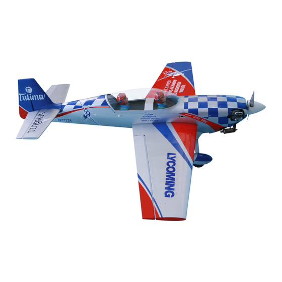
SIZE: 46-62
MS:199
ASSEMBLY MANUAL
"Graphics and specifications may change without notice".
Specifications:
Wing span ------------------------------54.9 in ( 139.5cm).
Wing area -----------------517.7 sq.in ( 33.4sq dm).
Weight ------------------------6.6 lbs ( 3.0 kg).
Length ------------------------------44.4 in ( 112.9 cm).
Engine ------------------ 0.46 cu.in -----2-stroke.
0.62 cu.in -----4-stroke.
Radio ------------------- 4 channels with 5 servos.
Electric conversion: optional
Advertisement
Table of Contents

Subscribe to Our Youtube Channel
Related Manuals for Seagull Models EXTRA EA 300L


Summary of Contents for Seagull Models EXTRA EA 300L
- Page 1 SIZE: 46-62 MS:199 ASSEMBLY MANUAL “Graphics and specifications may change without notice”. Specifications: Wing span ------------------------------54.9 in ( 139.5cm). Wing area -----------------517.7 sq.in ( 33.4sq dm). Weight ------------------------6.6 lbs ( 3.0 kg). Length ------------------------------44.4 in ( 112.9 cm). Engine ------------------ 0.46 cu.in -----2-stroke. 0.62 cu.in -----4-stroke.
-
Page 2: Kit Contents
EXTRA EA 300l - 1395mm INTRODUCTION. Thank you for choosing the EXTRA EA300L by SEAGULL MODELS. The EXTRA EA300L was designed with the intermediate/advanced sport flyer in mind. It is a semi scale airplane which is easy to fly and quick to assemble. The airframe is conventionally built using balsa, plywood to make it stronger than the average ARTF , yet the design allows the aeroplane to be kept light. -
Page 3: Hinging The Ailerons
www.seagullmodels.com KIT CONTENTS. HINGING THE AILERONS . Note: The control surfaces, including the Fuselage ailerons, elevators, and rudder, are Wing set prehinged with hinges installed, but Tail set the hinges are not glued in place. It Canopy is imperative that you properly Pilot adhere the hinges in place per the Cowling... -
Page 4: Hinging The Elevator
Instruction Manual. EXTRA EA 300l - 1395mm Hinge. 4)Deflect the aileron and completely 5) Turn the wing panel over and deflect the saturate each hinge with thin C/A glue. The aileron in the opposite direction from the ailerons front surface should lightly contact the opposite side. -
Page 5: Hinging The Rudder
www.seagullmodels.com HINGING THE RUDDER. Glue the rudder hinges in place using the same techniques used to hinge the ailerons. Hinge. LEDLIGHT Assembling the ledlight as shown below C/A glue pictures. INSTALL THE AILERONS CONTROL HORN. Locate the hardware necessary to install the control horns for the ailerons. - Page 6 Instruction Manual. EXTRA EA 300l - 1395mm Epoxy Epoxy Elevator INSTALL THE RUDDER CONTROL HORN. Repeat steps to install the rudder control horn as same as steps done for ailerons. Epoxy INSTALL ELEVATOR CONTROL HORN. Rudder Control Horn Install the elevator control horn using the same...
-
Page 7: Engine Mount Installation
www.seagullmodels.com ENGINE MOUNT INSTALLATION. 1) Locate the items necessary to install the engine mount included with your model. . M4x30mm. 2) Use four M4x30mm head bolts and four 4mm washers to attach the engine mount rails to the firewall. Tighten the screws . Make sure to use threadlock on the screws to help prevent them from vibrating loose. -
Page 8: Fuel Tank Installation
Instruction Manual. EXTRA EA 300l - 1395mm 6) When satisfied with the alignment of the stopper assembly tighten the 3 x 20mm machine screw until the rubber stopper ex- Vent tube. pands and seals the tank opening. Do not overtighten the assembly as this could cause the tank to split. - Page 9 www.seagullmodels.com 1) The blind nuts for securing the landing gear are already mounted inside the fuselage. 2) Using the hardware provided, mount M4x20mm the main landing gear to the fuselage. 3) Place the fuselage inverted on the work- Thread locker glue. bench in a suitable stand.
-
Page 10: Installing The Fuselage Servos
Instruction Manual. EXTRA EA 300l - 1395mm 3) You have to trim each axle using a tool cutting and cut-off wheel. 4) Slide the collar to the axle and setscrew the collars to secure the collar to the axle and... - Page 11 www.seagullmodels.com Rudder Throttle Trim and cut. Elevator THROTTLE SERVO ARM INSTALLATION. Install adjustable servo connector in the servo arm as same as picture below: Loctite secure. Adjustable Servo Switch. connector. Servo arm. 1 PCS. MOUNTING THE ENGINE. Rudder 1) Position the engine with the drive washer Throttle (110mm) forward of the firewall as shown.
- Page 12 Instruction Manual. EXTRA EA 300l - 1395mm 2mm. Pushrod wire. Machine screw M3x25mm. 3) Use a drill to drill the four holes in the engine mount rails. 2 mm. Pushrod wire 4) On the fire wall has the location for the 8) Reinstall the servo horn by sliding the throttle pusshrod tube (pre-drill).
- Page 13 www.seagullmodels.com Because of the size of the cowl, it may be nec- essary to use a needle valve extension for the high speed needle valve. Make this out of suf- ficient length 1.5mm wire and install it into the end of the needle valve. Secure the wire in place by tightening the set screw in the side of the needle valve.
- Page 14 Instruction Manual. EXTRA EA 300l - 1395mm 3) Install the muffler and muffler extension onto the engine and make the cutout in the cowl for muffler clearance. Connect the fuel and pressure lines to the carburetor, muffler and fuel filler valve. Secure the cowl to fuse- lage using the 3x10mm screws.
-
Page 15: Speed Control
www.seagullmodels.com Epoxy. 110mm Balsa 3) Attach the motor to the front of the electric motor box using four 4mm blind nut, four M3x15mm hex head bolts to secure the motor. Please see picture shown. Nut M3 Epoxy Speed Control 3 x 15mm speed control. -
Page 16: Installing The Aileron - Flap Servos
Instruction Manual. EXTRA EA 300l - 1395mm INSTALLING THE AILERON - FLAP SERVOS. Battery INSTALLING THE SPINNER. Install the spinner backplate, propeller and spinner cone. Servos. Small weight. Thread. Because the size of servos differ, you may need to adjust the size of the precut open- ing in the mount. - Page 17 www.seagullmodels.com C/A glue 4) Apply 2-3 drops of thin C/A to each of the mounting holes. Allow the C/A to cure without using accelerator. 5) Use dental floss to secure the connection so they cannot become unplugged. 6) Secure the servo to the aileron hatch using Phillips screwdriver and the screws provided with the servo.
-
Page 18: Installing The Horizontal Stabilizer
Instruction Manual. EXTRA EA 300l - 1395mm Bend at the mark Metal clevis. M2 lock nut. Snap keeper. 2 x 10mm Servo arm. Snap keeper. 2x10mm Fuel Tubing Nylon Snap Keeper AILERON PUSHROD HORN INSTALLATION INSTALLING THE HORIZONTAL STABILIZER. Fuel Tubing... - Page 19 www.seagullmodels.com 2) Using a modeling knife, carefully remove the covering at mounting slot of horizontal stabilizer. 3) Put the stabilizer into place in the position of the fuselage. Remove covering 7) Remove the stabilizer. Using the lines you just drew as a guide, carefully remove the covering from between them using a model- ing knife.
-
Page 20: Installing The Vertical Stabilizer
Instruction Manual. EXTRA EA 300l - 1395mm 9) When you are sure that everything is INSTALLING THE VERTICAL STABILIZER. aligned correctly, mix up a generous amount of 30 Minute Epoxy. Apply a thin layer to the bottom of the stabilizer mounting area and to the stabilizer mounting platform sides in the fuselage. - Page 21 www.seagullmodels.com While holding the vertical stabilizer firmly in place, use a pen and draw a line on each side of the vertical stabilizer where it meets the top of the fuselage. Epoxy Hinge C/A glue ELEVATOR PUSHROD HORN INSTALLATION. 3) Slide the vertical stabilizer back in 1) Install the elevator control horn using place.
- Page 22 Instruction Manual. EXTRA EA 300l - 1395mm 4) Elevator and rudder pushrods assembly M2 lock nut . M2 clevis. as pictures below. 460mm. M2 clevis. M2 lock nut . Cut. M 2 Clevis Fuel Tubing Hex Nut 8 mm 8 mm...
- Page 23 www.seagullmodels.com Fuel Tubing M2 Clevis Hex Nut 2) Install servos arm to servos. Notice the position of the servo arms on the servos. See picture below. MOUNTING THE TAIL WHEEL. Locate items necessary to install tail wheel. 3x25 mm. Wire keeper Aluminum tail landing gear.
- Page 24 Instruction Manual. EXTRA EA 300l - 1395mm 2) A scale pilot is included with this ARF. The Seagull Pilot included fitting well to the cockpit. (or you can order others scale pilot figures made by Seagull factory. They are available at Seagull distributors.)
- Page 25 www.seagullmodels.com ATTACHMENT WING-FUSELAGE. Attach the aluminium tube into fuselage. 2x6mm C/A glue Wing Tube 5) Install the canopy and secure it with M2x6mm screws. APPLY THE DECALS. Insert two wing panels as pictures below. 1) If all the decals are precut and ready to stick.
-
Page 26: Control Throws
Instruction Manual. EXTRA EA 300l - 1395mm BALANCING. 1) It is critical that your airplane be *If possible, first attempt to balance the model balanced correctly. Improper balance will by changing the position of the receiver battery cause your plane to lose control and crash. -
Page 27: Flight Preparation
A) Plug in your radio system per the 2) Check every bolt and every glue joint manufacturer's instructions and turn every- in the EXTRA EA 300l to ensure that thing on. everything is tight and well bonded. B) Check the elevator first. Pull back 3) Double check the balance of the air- on the elevator stick.
Need help?
Do you have a question about the EXTRA EA 300L and is the answer not in the manual?
Questions and answers