Table of Contents
Advertisement
Quick Links
Code : SEA 383
ASSEMBLY MANUAL
Speciications:
Wingspan ------------------- 75.5 in----------------------- 197 cm.
Wing Area ------------------ 1023 sp.in------------------- 66 sq.dm.
Weight ----------------------- 13 lbs------------------------ 5.9 kg.
Length ----------------------- 71 in------------------------- 179 cm.
Engine ----------------------- 35-40cc.
Radio ------------------------- 6 channels with 6 servos.
1
Advertisement
Table of Contents

Subscribe to Our Youtube Channel
Related Manuals for Seagull Models EDGE 540 V3


Summary of Contents for Seagull Models EDGE 540 V3
- Page 1 Code : SEA 383 ASSEMBLY MANUAL Speciications: Wingspan ------------------- 75.5 in----------------------- 197 cm. Wing Area ------------------ 1023 sp.in------------------- 66 sq.dm. Weight ----------------------- 13 lbs------------------------ 5.9 kg. Length ----------------------- 71 in------------------------- 179 cm. Engine ----------------------- 35-40cc. Radio ------------------------- 6 channels with 6 servos.
-
Page 2: Kit Contents
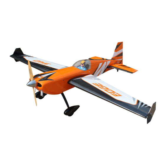
Edge 540 V3, 77.5” wingspan 35-40cc INTRODUCTION hank you for choosing the Edge 540 V3, 77.5” wingspan 35-40cc ARTF by SG MOD- ELS. he Edge 540 V3, 77.5” wingspan 35-40cc was designed with the intermediate/ad- vanced sport lyer in mind. It is a semi scale airplane which is easy to ly and quick to as- semble. -
Page 3: Install The Ailerons
KIT CONTENTS INSTALL THE AILERONS SEA383 Edge 540 V3, 77.5” wingspan Please see pictures below. 35-40cc 1. Fuselage 2. Wing set (2) 3. Tail set (2) 4. Cowling 5. Wing tube 6. Landing gear 7. Fuel tank 8. Tail wheel 9. - Page 4 Instruction Manual. Edge 540 V3, 77.5” wingspan 35-40cc Be sure to test the aileron hinges once you insert them. Ensure that the hinge pockets line up, and that the hinges move freely before the epoxy dries. Insert all four hinges in the ailerons at this time.
- Page 5 Prepare the aileron control horns by sand- ing the section that extends into the control surface with medium grit sand paper. Use iso- propyl alcohol and a paper towel to remove any excess debris from the control horn. Epoxy Epoxy Epoxy Fiberglass control horn...
-
Page 6: Installing The Aileron Servos
Instruction Manual. Edge 540 V3, 77.5” wingspan 35-40cc Fasten the pull string from the servo INSTALLING THE AILERON SERVOS hole to the male plug of the servo exten- sion. Please study images below. Maximum Servo spec. Torque : 126.6 oz-in (9.11 kg-cm) @ 6.0V;... - Page 7 Install servo with servo mounting screws. 38mm 3x15mm INSTALLING THE AILERON PUSHROD Please study images below. 90mm...
- Page 8 Instruction Manual. Edge 540 V3, 77.5” wingspan 35-40cc Repeat all the above steps for the other wing. Epoxy INSTALL HINGE FOR STABILIZER AND ELEVATOR Please study images below. Epoxy...
- Page 9 INSTALL ELEVATOR CONTROL HORN Fiberglass control horn Epoxy...
- Page 10 Instruction Manual. Edge 540 V3, 77.5” wingspan 35-40cc You cut horizontal tail sevor hole. Epoxy...
- Page 11 Maximum Servo spec. Torque : 126.6 oz-in (9.11 kg-cm) @ 6.0V; 178 oz-in (12.82 kg-cm) @ 7.4V; 248 oz- in (17.86 kg-cm) @ 8.4V INSTALL HINGE FOR RUDDER AND Please study images below. Please study images below. Epoxy Epoxy...
- Page 12 Instruction Manual. Edge 540 V3, 77.5” wingspan 35-40cc INSTALL RUDDER CONTROL HORN...
-
Page 13: Horizontal Tail Installation
HORIZONTAL TAIL INSTALLATION Please study images below. M3x12mm ELEVATOR PUSHROD INSTALLATION Please study images below. 140mm... - Page 14 Instruction Manual. Edge 540 V3, 77.5” wingspan 35-40cc NSTALL RUDDER CABLE AND SERVO NOTE : servos arm is not provided from manufacturer. 140mm 38mm Tape the rudder balance tab to the top leading edge of the vertical in in the neutral position as shown.
- Page 15 Cut of excess cable as shown. Loop the cable back through the brass swage tube and tighten the second loop through the brass swage tube as shown. Crimp the brass tube with a crimping tool or pliers.
- Page 16 Instruction Manual. Edge 540 V3, 77.5” wingspan 35-40cc Feed one rudder cable through the pre installed cable exit tube in the rear of the fuse toward the front of the fuse. Repeat for other side. Crimp the brass swage tube with a crimping tool or pliers.
-
Page 17: Tail Wheel Installation
C/A glue TAILWHEEL INSTALLATION Locate items necessary to install tailwheel. 3x15mm... - Page 18 Instruction Manual. Edge 540 V3, 77.5” wingspan 35-40cc M3x15mm...
- Page 19 INSTALLING THE MAIN LANDING GEAR TO FUSELAGE Please study images below. 3x4mm...
- Page 20 Instruction Manual. Edge 540 V3, 77.5” wingspan 35-40cc 3x4mm 3x10mm...
- Page 21 Loctite 4x20mm 3x10mm Loctite 4x20mm...
-
Page 22: Installing The Stopper Assembly
Instruction Manual. Edge 540 V3, 77.5” wingspan 35-40cc INSTALLING THE ENGINE SWITCH Trim and cut INSTALLING THE RECEIVER SWITCH Install the switch into the precut hole in the Switch side, in the fuselage. INSTALLING THE STOPPER ASSEMBLY Using a modeling knife, carefully cut... -
Page 23: Fuel Tank Installation
Slide the fuel tank into the fuselage. Guide Vent tube Fuel pick up tube the lines from the tank through the hole in the iewall. Fuel ill tube Carefully bend the second nylon tube up at a 45º angle. his tube is the vent tube. Test it the stopper assembly into the tank. -
Page 24: Mounting The Engine
Instruction Manual. Edge 540 V3, 77.5” wingspan 35-40cc MOUNTING THE ENGINE M5x80mm Use a 5.2mm bit to drill the engine mounting holes. 5.2mm Tighten mounting bolts and secure engine to irewall. Remove mounting template from irewall. Firewall shown with mounting... -
Page 25: Throttle Servo Installation
Install adjustable servo connector in the THROTTLE SERVO INSTALLATION servo arm as same as picture below: servo arm Install throttle servo into servo mount ing tray Use a 1/4” bit to drill a pushrod exit hole in the irewall in line with the engine carburetor throttle arm. -
Page 26: Ignition Installation
Instruction Manual. Edge 540 V3, 77.5” wingspan 35-40cc Secure ignition wire with nylon ties as IGNITION INSTALLATION necessary. I hread nylon tie through mounting holes. 170mm Connect ignition module to pickup line of engine. Secure with Safety Clip, safety wire, tape or other method. - Page 27 Tape the cowl to the fuselage using low-tack tape. COWLING Please study images below.
- Page 28 Instruction Manual. Edge 540 V3, 77.5” wingspan 35-40cc Use a drill and drill bit to drill the holes for the cowl mounting screws. Make sure the cowl position is correct before drilling each hole. Install the muler and muler extension onto the engine and make the cutout in the cowl for muler clearance.
- Page 29 ELECTRIC POWER CONVERSION Locate the items neccessary to install the electric power conversion included with your model. M5x30mm and washers Recommend the items necessary to install the electric power conversion parts included with your model. - M o t o r : 1 8 0 / 3 0 0 0 - 3 5 0 0 Watts - Propeller: 20x8 ~ 21x10 - ESC: 80A - 120A...
- Page 30 Instruction Manual. Edge 540 V3, 77.5” wingspan 35-40cc hen, use 5mm drill bit to enlarge the holes on the electric motor box. 6.5mm Attach the speed control to the side of the motor box using two-sided tape and Attach the motor mount to the front tie wraps.
-
Page 31: Installing The Spinner
INSTALLING THE SPINNER Install the spinner backplate, propeller and spinner cone. Battery he propeller should not touch any part of the spinner cone. If it does, use a sharp modeling knife and carefully trim away the spinner cone where the propel- ler comes in contact with it. - Page 32 Instruction Manual. Edge 540 V3, 77.5” wingspan 35-40cc A scale pilot is included with this ARF. he Pilot included itting well to the cock- pit. (or you can order others scale pilot igures made by SG Models. hey are available at SG Models distributors.)
- Page 33 INSTALL WING TIP 4x12mm Please study images below.
-
Page 34: Apply The Decals
Instruction Manual. Edge 540 V3, 77.5” wingspan 35-40cc If all the decals are not precut, please use scissors or a sharp hobby knife to cut the decals from the sheet. Please be certain the model is clean and free from oily in- gerprints and dust. -
Page 35: Control Throws
Lit the model. If the tail drops when CONTROL THROWS you lit, the model is “tail heavy” and you must add weight* to the nose. If the nose Ailerons: Rudder: drops, it is “nose heavy” and you must High Rate : High Rate : add weight* to the tail to balance. -
Page 36: Flight Preparation
Instruction Manual. Edge 540 V3, 77.5” wingspan 35-40cc FLIGHT PREPARATION PREFLIGHT CHECK Check the operation and direction of the 1) Completely charge your transmit- elevator, rudder, ailerons and throttle. ter and receiver batteries before your irst day of lying. A) Plug in your radio system per the 2) Check every bolt and every glue manufacturer’s instructions and turn eve-... - Page 37 If you have any queries, or are interested in our products, please feel free to contact us Factory : 12/101A - Hamlet 4 - Le Van Khuong Street - Dong hanh Ward - Hoc Mon District - Ho Chi Minh City - Viet Nam. Oice : 62/8 Ngo Tat To Street - Ward 19 - Binh hanh District - Ho Chi Minh City - Viet Nam Phone : 848 - 86622289 or 848- 36018777...
Need help?
Do you have a question about the EDGE 540 V3 and is the answer not in the manual?
Questions and answers