Table of Contents
Advertisement
Quick Links
MS:176
ASSEMBLY MANUAL
"Graphics and specifications may change without notice".
Specifications:
Wing span ------------------------------98.4in (250cm).
Wing area ----------------1576.4sq.in (101.7sq dm).
Weight ----------------------13.2-15.4lbs (6.0-7.0kg).
Length ------------------------------67.3in (171.0cm).
Engine ------------------ -----------33-40cc.
Radio -------------------6 channels with 7 servos.
Advertisement
Table of Contents

Related Manuals for Seagull Models ERCOUPE


Summary of Contents for Seagull Models ERCOUPE
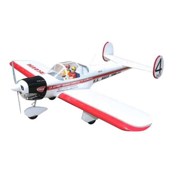
- Page 1 MS:176 ASSEMBLY MANUAL “Graphics and specifications may change without notice”. Specifications: Wing span ------------------------------98.4in (250cm). Wing area ----------------1576.4sq.in (101.7sq dm). Weight ----------------------13.2-15.4lbs (6.0-7.0kg). Length ------------------------------67.3in (171.0cm). Engine ------------------ -----------33-40cc. Radio -------------------6 channels with 7 servos.
-
Page 2: Kit Contents
Thank you for choosing the ERCOUPE ARTF by SEAGULL MODELS COMPANY LTD. The ERCOUPE was designed with the intermediate/advanced sport flyer in mind. It is a semi scale airplane which is easy to fly and quick to assemble. The airframe is conventionally built using balsa, plywood to make it stronger than the average ARTF , yet the design allows the aeroplane to be kept light. - Page 3 www.seagullmodels.com INSTALL THE AILERONS CONTROL CONTENTS.TS HORN. Fuselage 1) Locate the hardware necessary to install Wing Set the control horns for the ailerons. Tail Set Cowling Main Landing Gear Wing Tube Hardware Set Fiberglass Wheel Pants Canopy Pilot Fuel Tank Fiberglass control horn 2)Position the Control horn on the Aileron and use 30-minute Epoxy...
-
Page 4: Installing The Fuselage Servos
Instruction Manual. ERCOUPE Position the Control horn on the Aileron and Rudder control horn. use 30-minute Epoxy Epoxy. INSTALLING THE FUSELAGE SERVOS. Because the size of servos differ, you may need to adjust the size of the precut open- ing in the mount. The notch in the sides of the mount allow the servo lead to pass through. -
Page 5: Installing The Switch
www.seagullmodels.com INSTALLING THE STOPPER ASSEMBLY. Throttle servo arm. 1) Using a modeling knife, carefully cut off the rear portion of one of the 3 nylon tubes leaving 1/2” protruding from the rear of the stopper. This will be the fuel pick up tube. 2) Using a modeling knife, cut one length of silicon fuel line. -
Page 6: Fuel Tank Installation
Instruction Manual. ERCOUPE 8) Use plywood template to hold in place 3) Carefully bend the second nylon tube the fuel tank with C/A glue to secure the fuel up at a 45º angle. This tube is the vent tube. tank inside the fuselage. -
Page 7: Mounting The Engine
www.seagullmodels.com MOUNTING THE ENGINE. 5 x 80 mm 150mm 5.2mm 5x80mm. Screw. -
Page 8: Nose Landing Gear
Instruction Manual. ERCOUPE 2)Install nose landing gear and wheel pant. Screw. Thread locker glue. M3x25mm. Screw. Screw. Drill hole. NOSE LANDING GEAR INSTALLTION. 5.2mm 1)Locate the items necessary to attach the nose landing gear that are included with your model. - Page 9 www.seagullmodels.com Axle. wheel collar wheel 3)Install nose landing gear at the top Fuselage. Screw. 3)Install nose landing gear at the top Fuselage.
- Page 10 Instruction Manual. ERCOUPE COWLING. 1)Slide the fiberglass cowl over the engine and line up the back edge of the cowl with the marks you made on the fuselage then trim and cut as shown. Crimp. Cableend. Trim and cut. Because of the size of the cowl, it may be nec- essary to use a needle valve extension for the high speed needle valve.
-
Page 11: Installing The Spinner
www.seagullmodels.com 2) While keeping the back edge of the INSTALLING THE SPINNER. cowl flush with the marks, align the front of Install the spinner backplate, propeller and the cowl with the crankshaft of the engine. The spinner cone. front of the cowl should be positioned so the crankshaft is in nearly the middle of the cowl opening. - Page 12 Instruction Manual. ERCOUPE 4) Apply 2-3 drops of thin C/A to each of the Servos. Small weight. mounting holes. Allow the C/A to cure without using accelerator. Thread. Because the size of servos differ, you may need to adjust the size of the precut open- ing in the mount.
- Page 13 www.seagullmodels.com 9) Set the aileron hatch in place and use a 8) A string has been provided in the wing to Phillips screw driver to install it with four wood pull the aileron lead through to the wing root. screws. Remove the string from the wing at the servo location and use the tape to attach it to the servo extension lead.
- Page 14 Instruction Manual. ERCOUPE LANDING GEAR INSTALLTION. 1)Locate the items necessary to attach the landing gear that are included with your model. 1)Locate the items necessary to attach the 2 mm landing gear that are included with your model. Epoxy M3 X 25 mm...
- Page 15 www.seagullmodels.com Thread locker glue 3x10 mm 5.2mm 5.2mm...
- Page 16 Instruction Manual. ERCOUPE TAIL SET INSTALLTION. ATTACHMENT TAIL SET-FUSELAGE. Epoxy Epoxy...
-
Page 17: Installation
www.seagullmodels.com Elevator pushrod. Control horn. 4x45mm Metal clevis. M2 lock nut. ELEVATOR PUSHROD HORN ELEVATOR PUSHROD HORN INSTALLATION. INSTALLATION. 1) Install the elevator control horn using the same method as with the aileron control horns. 2) Position the elevator control horn on the both side of elevator. -
Page 18: Apply The Decals
Instruction Manual. ERCOUPE INSTALLATION PILOT AND CANOPY. 1) Locate items necessary to install pilot, cockpit panel, and canopy. Epoxy. M2x6mm. 2) A scale pilot is included with this ARF. The Seagull Pilot included fitting well to the cockpit. (or you can order others scale pilot figures 4) Position the canopy onto the fuselage. - Page 19 www.seagullmodels.com INSTALLING ANTENNA AND THE BATTERY-RECEIVER. 1) Plug the five servo leads and the switch lead into the receiver. Plug the battery pack lead into the switch also. 2) Wrap the receiver and battery pack in Wing bolt. the protective foam rubber to protect them from vibration.
- Page 20 Instruction Manual. ERCOUPE BALANCING. 1) It is critical that your airplane be balanced correctly. Improper balance will cause your plane to lose control and crash. THE CENTER OF GRAVITY IS LOCATED 110 MM BACK FROM THE LEADING EDGE OF THE WING AT THE WING ROOT.
-
Page 21: Control Throws
www.seagullmodels.com CONTROL THROWS. Ailerons: Rudder: High Rate : High Rate : Up : 18 mm Right : 25 mm Down : 18 mm Left : 25 mm Low Rate : Low Rate : Up : 10 mm Right : 20 mm Down : 10 mm Left : 20 mm Elevator:... -
Page 22: Flight Preparation
2) Check every bolt and every glue joint A) Plug in your radio system per the in the ERCOUPE to ensure that everything is manufacturer's instructions and turn every- tight and well bonded. thing on.
Need help?
Do you have a question about the ERCOUPE and is the answer not in the manual?
Questions and answers