Table of Contents
Advertisement
Quick Links
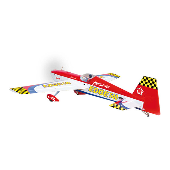
EDGE 540
Hand-made Almost Ready to Fly R/C Model Aircraft
Specifications
Wingspan---------------------------------------- 77.5 in---------------------------- 197cm.
Wing area--------------------------------------- 1023sq.in--------------------- 66 sq.dm.
Approximate flying weight------------------ 10.6-13lbs------------------- 4.8-5.8kg.
Length-------------------------------------------- 71 in------------------------------- 179cm.
Recommended engine size--------------- 1.60 cu.in---------------------- 2-stroke.
Radio System required 6 channel with 6 digital servos - 6.5kg/cm.
Flying skill level Intermediate/advanced.
Kit features.
•
Ready-made—minimal assembly & finishing required.
•
Ready-covered covering.
•
Photo-illustrated step-by-step Assembly Manual.
Made in Vietnam.
ASSEMBLY MANUAL
"Graphics and specfications may change without notice".
1.80 cu.in--------------- 4-stroke.
MS: 26
.
2
Advertisement
Table of Contents

Related Manuals for Seagull Models EDGE 540


Summary of Contents for Seagull Models EDGE 540
- Page 1 EDGE 540 MS: 26 Hand-made Almost Ready to Fly R/C Model Aircraft ASSEMBLY MANUAL “Graphics and specfications may change without notice”. Specifications Wingspan---------------------------------------- 77.5 in---------------------------- 197cm. Wing area--------------------------------------- 1023sq.in--------------------- 66 sq.dm. Approximate flying weight------------------ 10.6-13lbs------------------- 4.8-5.8kg. Length-------------------------------------------- 71 in------------------------------- 179cm.
-
Page 2: Fuselage Assembly
ARTF , yet the design allows the aeroplane to be kept light. You will find that most of the work has been done for you already.Flying the EDGE 540 is simply a joy. This instruction manual is designed to help you build a great flying aeroplane. Please read this manual thoroughly before starting assembly of your EDGE 540. -
Page 3: Hinging The Ailerons
Hinge. and are aligned properly before gluing! This will ensure proper assembly as the EDGE 540 is made from natural materials and minor adjustments may 3) Slide the aileron on the wing panel until have to be made. -
Page 4: Installing The Aileron Servos
EDGE 540. Instruction Manual. 5) Turn the wing panel over and deflect the aileron in the opposite direction from the opposite side. Apply thin C/A glue to each hinge, making sure that the C/A penetrates into both the aileron and wing panel. -
Page 5: Installing The Stopper Assembly
www.seagullmodels.com Electric wire. 4x30mm. Thread. Mark and drill 4 holes for engine mount. Attach the thread to the servo lead and carefully thread it though the wing. Once you have thread the lead throught the wing, remove the string so it can use for the other servo lead. - Page 6 EDGE 540. Instruction Manual. 5) With the stopper assembly in place, the weighted pick up should rest away from the rear of the tank and move freely inside the tank. The top of the vent tube should rest just below the top of the tank. It should not touch the top of the tank.
- Page 7 www.seagullmodels.com Vent tube. 7mm. 14mm. 3) You have to trim each axles and using a tool cutting and cut-off wheel. Fuel pick up tube. Fuel fill tube. Caution when cutting the axles and wear protective goggles. Blow through one of the lines to ensure the fuel lines have not become kinked inside the fuel tank compartment.
-
Page 8: Installing The Main Landing Gear
EDGE 540. Instruction Manual. INSTALLING THE FUSELAGE SERVO. Engine 2 stroke. Throttle servo. Landing gear. Rudder servo. Engine 4 stroke. Servo tray. 4) A drop of Thread locker glue on the wheel collar screws will help keep them from coming lose during operation. -
Page 9: Mounting The Engine
www.seagullmodels.com 4) Remove the engine. Using an drill bit, Left side. drill the mounting holes through the engine mount at the four locations marked. Remove covering. 2) Install the rubber grommets and brass collets onto the elevator servo. Test fit the servo into the elevator servo mount. - Page 10 EDGE 540. Instruction Manual. 2) While keeping the back edge of the cowl flush with the marks, align the front of the cowl with the crankshaft of the engine. The front of the cowl should be positioned so the crankshaft is in nearly the middle of the cowl opening.
-
Page 11: Installing The Switch
www.seagullmodels.com 3x10mm(6pcs). INSTALLING THE SWITCH. Install the switch into the precut hole in the side of the fuselage. INSTALLING THE SPINNER. 1) Install the spinner backplate, propeller and spinner cone. (spinner is not included). The propeller should not touch any part of the spinner cone. -
Page 12: Vertical Stabilizer Installation
EDGE 540. Instruction Manual. INSTALLING HORIZONTAL FIN. 1) Remove the covering at the rear tail root of horizontal fin as picture shown below. 2)Sand the aluminium tube using sandpaper. This will improve the bond of the 3x10mm. epoxy to the cardboard horizontal fin. - Page 13 www.seagullmodels.com When cutting through the covering to re- of the fuselage and the lower rudder hinge move it, cut with only enough pressure to only should engage the precut hinge slot in the cut through the covering itself. Cutting into lower fuselage.
-
Page 14: Aileron Control Horn Installation
EDGE 540. Instruction Manual. Repeat the procedure for orther wing. AILERON CONTROL HORN INSTALLATION. ELEVATOR CONTROL HORN INSTALLATION. Repeat the procedure for the elevator control horn as same as the way of aileron control horn. 3x50mm. Horizontal fin. Elevator. 1) Aileron control horn:... -
Page 15: Aileron Pushrod Installation
www.seagullmodels.com Elevator pushrod. vetical fin. Repeat the procedure for orther elevator. AILERON PUSHROD INSTALLATION. Repeat the procedure for wing panel as same as elevator pushrod. Rudder control horn. Pushrod L= 125mm . Metal clevis. RUDDER PULL - PULL CABLE SYSTEM. See pictures below: Repeat the procedure for orther aileron. -
Page 16: Mounting The Tail Wheel
EDGE 540. Instruction Manual. Cable wire. 1) Insert servo arm into servo. MOUNTING THE TAIL WHEEL. See picture below M3 x20 mm. 2) With the radio on, check the operation of the rudder. Adjust the cables so when the rudder servo is centered, the rudder is centered as well. - Page 17 www.seagullmodels.com Receiver. Battery. Tie wrap. THROTTLE SERVO ARM INSTALLATION. ) Install adjustable servo connector in the servo arm. Adjustable Servo connector. Servo arm. Antenna wire. 2) Install the pushrod throttle. Throttle. Antenna. ATTACHMENT WING-FUSELAGE. Attach the aluminium tube into fuselage. INSTALLING THE BATTERY-RECEIVER.
-
Page 18: Control Throws
Wing bolt. 95 - 110mm. CONTROL THROWS. We highly recommend setting up the EDGE 540 using the control throws listed at right. We have listed control throws for both Low Rate (initial test flying/sport flying) and High Rate (aerobatic flying). -
Page 19: Flight Preparation
2) Check every bolt and every glue joint in the EDGE 540 to ensure that everything is tight and well bonded. 3) Double check the balance of the air- plane. Do this with the fuel tank empty.
Need help?
Do you have a question about the EDGE 540 and is the answer not in the manual?
Questions and answers