Table of Contents
Advertisement
Quick Links
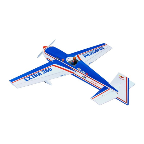
Specifications
Wingspan ------------------------------ 63 in -------------------------- 160cm.
Wing area ----------------------------- 728 sq.in ------------------ 47 sq.dm.
Weight ---------------------------------- 8.4-9.9lbs -----------------3.8-4.5kg.
Length ---------------------------------- 59.4 in ------------------------- 151cm.
Recommended engine size ------ .91-1.25 cu.in ----------- 2-4stroke.
Radio System required 6 channel with 6 digital servos.
Flying skill level -------------------- Intermediate/advanced.
Kit features.
•
Ready-made—minimal assembly & finishing required.
•
Ready-covered covering.
•
Photo-illustrated step-by-step Assembly Manual.
Made in Vietnam.
ASSEMBLY MANUAL
MS:56H
Advertisement
Table of Contents

Related Manuals for Seagull Models EXTRA 260


Summary of Contents for Seagull Models EXTRA 260
- Page 1 MS:56H ASSEMBLY MANUAL Specifications Wingspan ------------------------------ 63 in -------------------------- 160cm. Wing area ----------------------------- 728 sq.in ------------------ 47 sq.dm. Weight ---------------------------------- 8.4-9.9lbs -----------------3.8-4.5kg. Length ---------------------------------- 59.4 in ------------------------- 151cm. Recommended engine size ------ .91-1.25 cu.in ----------- 2-4stroke. Radio System required 6 channel with 6 digital servos. Flying skill level -------------------- Intermediate/advanced.
- Page 2 ARTF , yet the design allows the aeroplane to be kept light. You will find that most of the work has been done for you already.Flying the EXTRA 260 is simply a joy. This instruction manual is designed to help you build a great flying aeroplane. Please read this manual thoroughly before starting assembly of your EXTRA 260.
- Page 3 Please trial fit all parts. Make sure you have the correct parts and that they fit and are aligned properly before gluing! This will ensure proper assembly as the EXTRA 260 is made from natural materials and minor adjustments may have to be made.
-
Page 4: Hinging The Ailerons
EXTRA 260. Instruction Manual. HINGING THE AILERONS. Note: The control surfaces, including the T-pin. ailerons, elevators, and rudder, are prehinged with hinges installed, but the hinges are not glued in place. It is imperative that you properly adhere the hinges in place per the steps that follow using a high-quality thin C/A glue. -
Page 5: Hinging The Rudder
www.seagullmodels.com HINGING THE RUDDER. Glue the rudder hinges in place using the same tectniques used to hinge the ailerons. C/A glue. ! 6) Using C/A remover/debonder and a paper towel, remove any excess C/A glue that may have accumulated on the wing or in the aileron hinge area. - Page 6 EXTRA 260. Instruction Manual. ! 3) Carefully bend the second nylon tube ! 5) With the stopper assembly in place, up at a 45º angle. This tube is the vent tube. the weighted pick-up should rest away from the rear of the tank and move freely inside the Balsa wood.
-
Page 7: Elevator Servo Installation
www.seagullmodels.com Vent tube. Left side. Elevator servo. Fuel pick-up tube. Fuel fill tube. INSTALLING THE FUSELAGE SERVO. Blow through one of the lines to ensure the fuel lines have not become kinked inside Engine .91 - 2 stroke. the fuel tank compartment. Air should flow through easily. -
Page 8: Installing The Switch
EXTRA 260. Instruction Manual. Switch. INSTALLING THE AILERON SERVOS. Small weight. Rudder servo. Thread. Servos. We recommended to use long servos arm ( 70mm diameter) for all servos without throttle Throttle servo. servo. Install the rubber grommets and brass collets onto the aileron servo. Test fit the servo into the aileron servo mount. -
Page 9: Horizontal Stabilizer
www.seagullmodels.com Attach the string to the servo lead and Wing panel bottom. carefully thread it though the wing. Once you have thread the lead throught the wing, remove the string so it can use for the other servo lead. Tape the servo lead to the wing to prevent it from falling back into the wing. -
Page 10: Vertical Stabilizer Installation
EXTRA 260. Instruction Manual. and realign. Double check all of your mea- surements once more before the epoxy cures. Hold the stabilizer in place with T-pins or mask- ing tape and remove any excess epoxy using a paper towel and rubbing alcohol. - Page 11 www.seagullmodels.com ! 1) Using a modeling knife, remove the ! 4) Remove the stabilizer. Using a mod- covering from over the precut hinge slot cut eling knife, remove the covering from below into the lower rear portion of the fuselage. This the lines you drew.
-
Page 12: Installing The Aileron Linkage
EXTRA 260. Instruction Manual. Wing bottom. M3 lock nut. M3 control horn. M3 nut. C/A glue. Aluminium washer. Aileron control horn. Wing bottom. Repeat the procedure for orther wing. ELEVATOR CONTROL HORN INSTALLATION. 1) Elevator control horn: INSTALLING THE AILERON LINKAGE. -
Page 13: Rudder Control Horn Installation
www.seagullmodels.com Repeat the procedure for orther elevator. RUDDER CONTROL HORN INSTALLATION. ! 1) Position the rudder control horn on the left - right side of the rudder. ! 2) Locate the two nylon control horns, two nylon control horn backplates and three machine screws. -
Page 14: Elevator Pushrod Installation
EXTRA 260. Instruction Manual. ! 1) Insert servo arm into servo. Repeat the procedure for orther aileron. ELEVATOR PUSHROD INSTALLATION. Repeat the procedure for elevator pushrod as same as aileron pushrod. ! 2) With the radio on, check the operation 150mm. - Page 15 www.seagullmodels.com 7mm. 14mm. WHEEL AND WHEEL PANTS. ! 3) You have to trim each axles and using a tool cutting and cut-off wheel. Caution when cutting the axles wear protective goggles. ! 1) Assemble and mounting the wheel pants as shown in the following pictures. 57mm.
-
Page 16: Mounting The Engine
EXTRA 260. Instruction Manual. INSTALLING THE MAIN LANDING GEAR. !1) The blind nuts for securing the landing gear are already mounted inside the fuselage. !2) Using the hardware provided, mount the main landing gear to the fuselage. 6 X 20mm. - Page 17 www.seagullmodels.com Engine 1.25 - 4 stroke. 4.2mm. 140mm. 5) Bolt the engine to the engine mount using the four machine screws. Double check that all the screws are tight before proceeding. 6) Attach the Z-Bend in the pushrod wire to the throttle arm on the carburetor.
-
Page 18: Installing The Spinner
EXTRA 260. Instruction Manual. Trim and cut. 1.5mm wire (needle valve). Because of the size of the cowl, it may be necessary to use a needle valve extension for the high speed needle valve. Make this out of sufficient length 1.5mm wire and install it into the end of the needle valve. - Page 19 www.seagullmodels.com 3.2mm drill bit. Turnbuckle. Horizontal stabilizer. M3 lock nut. INSTALLING TAIL STRUT SYSTEM. Tail strut system assembly follow pictures below. 14cm. 8cm. 0cm. 3x10mm.
-
Page 20: Mounting The Tail Wheel
EXTRA 260. Instruction Manual. ! 1) You have to trim each axles and using a tool cutting and cut-off wheel. Aluminium strap. Caution when cutting the axles wear protective goggles. 3x10mm. (1+2) Plastic clip. 3x25mm. ! 2) Set the tail wheel assembly in place. -
Page 21: Installing The Receiver
www.seagullmodels.com Throttle. ! 4) Secure the tail wheel bracket in place INSTALLING THE RECEIVER. using two 3x25mm wood screws. Be careful ! 1) Plug the six servo leads and the switch not to overtighten the screws. lead into the receiver. Plug the battery pack lead into the switch also. -
Page 22: Control Throws
CONTROL THROWS. We highly recommend setting up the EXTRA 260 using the control throws listed at right. We have listed control throws for both Low Rate (initial test flying/sport flying) and High Rate (aerobatic flying). - Page 23 3/4” down flying. Rudder: 2 1/2” right and left !2) Check every bolt and every glue joint AEROBATIC FLYING in the EXTRA 260 to ensure that everything is Ailerons: 1” up 7/8” down tight and well bonded. Elevator: 1 1/4” up 1 1/4”down...
Need help?
Do you have a question about the EXTRA 260 and is the answer not in the manual?
Questions and answers