Table of Contents
Advertisement
Quick Links
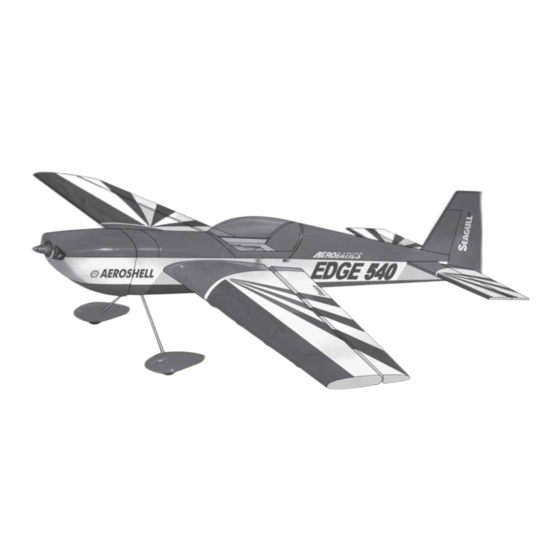
ALMOST READY TO FLY
"Graphics and specfications may change without notice".
Specifications
Wing Span ------------------------------- 42.7 in --------------------- 108.5cm.
Wing Area ------------------------------- 376.7 sq in ------------ 24.3 sq dm.
Weight --------------------------------- 2.4 - 2.9 Ibs------------ 1100 - 1300g.
Length ------------------------------------ 38.8 in ----------------------- 98.6cm.
Need to Complete
Speed Control: 45A - 50A amp.
Recommended Battery 3-cell 2200mAh to 3200mAh Li-Po.
Radio : 4 channel with 5 digital servos (medium size)
Kit features.
•
Ready-made—minimal assembly & finishing required.
•
Ready-covered covering.
•
Photo-illustrated step-by-step Assembly Manual.
Made in Vietnam.
ASSEMBLY MANUAL
MS: X12 A - B
2
Advertisement
Table of Contents

Related Manuals for Seagull Models EDGE 540 EP


Summary of Contents for Seagull Models EDGE 540 EP
-
Page 1: Specifications
ASSEMBLY MANUAL ALMOST READY TO FLY MS: X12 A - B “Graphics and specfications may change without notice”. Specifications Wing Span ------------------------------- 42.7 in --------------------- 108.5cm. Wing Area ------------------------------- 376.7 sq in ------------ 24.3 sq dm. Weight --------------------------------- 2.4 - 2.9 Ibs------------ 1100 - 1300g. Length ------------------------------------ 38.8 in ----------------------- 98.6cm. -
Page 2: Additional Items Required
EDGE 540. Instruction Manual. INTRODUCTION. Thank you for choosing the EDGE 540 ARTF by SEAGULL EP. The EDGE 540 was designed with the intermediate/advanced sport flyer in mind. It is a semi scale airplane which is easy to fly and quick to assemble. The airframe is conventionally built using balsa, plywood to make it stronger than the average ARTF , yet the design allows the aeroplane to be kept light. - Page 3 www.seagullmodels.com NOTE: To avoid scratching your new aero- TOOLS & SUPPLIES NEEDED. plane we suggest that you cover your Thick cyanoacrylate glue. workbench with an old towel. Keep a 30 minute epoxy. couple of jars or bowls handy to hold 5 minute epoxy.
-
Page 4: Hinging The Ailerons
EDGE 540. Instruction Manual. HINGING THE AILERONS. Note: The control surfaces, including the ailerons, elevators, and rudder, are C/A glue. prehinged with hinges installed, but the hinges are not glued in place. It is imperative that you properly adhere the hinges in place per the steps that follow using a high-quality thin C/A glue. -
Page 5: Hinging The Rudder
www.seagullmodels.com HINGING THE RUDDER. Glue the rudder hinges in place using the same tectniques used to hinge the ailerons. WHEEL AND WHEEL PANTS. C/A glue. Assemble and mounting the wheel pants as shown in the following pictures. C/A glue. C/A glue. A drop of C/A glue on the wheel collar screws will help keep them from coming lose during operation. - Page 6 EDGE 540. Instruction Manual. Wing bottom. Aileron servo. Fuselage bottom. Attach the micro control connector to the servo arms. Be sure to use the lock tie but it could free rotation . 2 X 12mm. AILERON SERVOS - LINKAGES. 1) Install the rubber grommets and brass eyelets onto the aileron servo.
-
Page 7: Horizontal Stabilizer
www.seagullmodels.com Left side. Elevator servo. HORIZONTAL STABILIZER. 1) Using a ruler and a pen, locate the centerline of the horizontal stabilizer, at the trail- ing edge, and place a mark. Use a triangle and extend this mark, from back to front, across the top of the stabilizer. -
Page 8: Vertical Stabilizer Installation
EDGE 540. Instruction Manual. Remove covering. Pen. Glued epoxy. 5) Remove the stabilizer. Using the lines you just drew as a guide, carefully remove the covering from between them using a model- ing knife. Covered wood filler piece Remove covering. VERTICAL STABILIZER INSTALLATION. -
Page 9: Control Horn Installation
www.seagullmodels.com Vertical Stabilizer. Horizontal 90º Stabilizer. 6) When you are sure that everything is aligned correctly, mix up a generous amount of 30 Minute Epoxy. Apply a thin layer to the mount- ing slot in the top of the fuselage and to the sides and bottom of the vertical stabilizer mounting area. -
Page 10: Pushrod Installation
EDGE 540. Instruction Manual. Rudder servo. C/A glue. Elevator control horn. Rudder control horn. Elevator servo. MOUNTING THE TAIL SKID. See pictures below: Elevator control horn. C/A glue. PUSHROD INSTALLATION. Pushrod install as same as method of C/A glue. pushrod wing. See pictures below. Pushrod. - Page 11 www.seagullmodels.com Insert blind nut. Remove the covering. INSTALLING THE BATTERY-RECEIVER. See pictures below: C/A glue. Battery. Tie wrap. Receiver. Battery. Motor. Tie wrap. INSTALLING ELECTRIC MOTOR. There are 2 mouting box for your option.It is depended your motor size. 4.5 mm.
-
Page 12: Cowling Installation
EDGE 540. Instruction Manual. The propeller should not touch any part of the spinner cone. If it does, use a sharp Speed control. modeling knife and carefully trim away the spinner cone where the propeller comes in contact with it. 5) Secure the cowl with the screw pro- vide with hardware. -
Page 13: Control Throws
www.seagullmodels.com Wing brace. Insert two wing panels as pictures below. 7 cm. BALANCING. 1) It is critical that your airplane be bal- anced correctly. Improper balance will cause your plane to lose control and crash. The cen- ter of gravity is locate back from the lead- ing edge of the wing, measured at wing tip. - Page 14 EDGE 540. Instruction Manual. Turn on the radio system, and with the E) Check the throttle. trim tabs on the transmitter in neutral, center F) From behind the airplane, look at the the control surfaces by making adjustments aileron on the right wing half. Move the aileron to the clevises or adjustable servo connectors.
Need help?
Do you have a question about the EDGE 540 EP and is the answer not in the manual?
Questions and answers