Icom IC-F8100 Instruction Manual
Hide thumbs
Also See for IC-F8100:
- Service manual (80 pages) ,
- Instruction manual (72 pages) ,
- Manual (3 pages)
Table of Contents
Advertisement
Quick Links
Advertisement
Table of Contents

Subscribe to Our Youtube Channel
Related Manuals for Icom IC-F8100


Summary of Contents for Icom IC-F8100
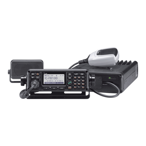
- Page 1 INSTRUCTION MANUAL HF TRANSCEIVER iF8100...
-
Page 2: Foreword
Icom’s state of the art technology and craftsmanship. With proper care, this product should provide you with years of trouble-free operation. We appreciate you making the IC-F8100 your radio of choice, and hope you agree with Icom’s philosophy of “technology first.” Many hours of research and develop- ment went into the design of your IC-F8100. -
Page 3: Precautions
DO NOT During mobile operation, operate the trans- mal odor, sound or smoke. Contact your Icom dealer or ceiver without running the vehicle’s engine. When the distributor for advice. transceiver’s power is ON and your vehicle’s engine is OFF, the vehicle’s battery will soon become exhausted. -
Page 4: Table Of Contents
TABLE OF CONTENTS FOREWORD .............. i IMPORTANT ............... i EXPLICIT DEFINITIONS ..........i PRECAUTIONS ............ii TABLE OF CONTENTS ........... iii 1 PANEL DESCRIPTION ........1–5 ■ Controller (Front panel or HM-192) ....1 ■ Rear panel ............3 ■ AD-119 Optional Junction Box ......4 ■... -
Page 5: Panel Description
PANEL DESCRIPTION ■ Controller (Front panel or HM-192) • HM-192 • Front panel Keypad (p. 2) i HOME/MENU KEY [HOME] [MENU](HOME) q VOLUME KEYS [ +]/[ –](p. 7) ➥ Push to return to the home display. Adjusts the audio output level. ➥... - Page 6 PANEL DESCRIPTION D Keypad ➥ Inputs numeral for the Clock Setting. ➥ Inputs numeral or alphabet for the Selcall direct input. 10-key GPS KEY [GPS] TUNER KEY [TUNER] When a GPS receiver is connected through the op- ➥ Hold down for 1 second to start manual tune the tional AD-119 Junction Box and valid data is received, optional automatic antenna tuner.
-
Page 7: Rear Panel
PANEL DESCRIPTION ■ Rear panel Protect plug ACC2 ACC1 q DC POWER CONNECTOR [DC] r ACCESSORY CONNECTOR (10 PIN) [ACC1] Accepts 13.8 V DC through the supplied DC power t ACCESSORY CONNECTOR (12 PIN) [ACC2] cable. Connect the optional AD-119 Junction Box. Both connectors must be connected to use the AD- w FAN CONNECTOR [FAN] 119. -
Page 8: Ad-119 Optional Junction Box
ACCESSORY CONNECTOR 1 (10 PIN) [ACC1] Input position and UTC data in NMEA0183 ver. 2.0 Connect to the IC-F8100’s Accessory connectors. or 3.01 formats, such as from a GPS receiver for Both connectors must be connected to use this automatically setting your position and time data. -
Page 9: Lcd Screen
PANEL DESCRIPTION ■ LCD screen • Memory Channel Display • Selcall Address Display • ALE ID Display q RECEIVE/TRANSMIT ICON i SUB READOUTS ➥ “ RX” appears when signals are received or the <Memory Channel display> squelch is open. Shows the transmit and receive frequencies of the ➥... -
Page 10: Basic Operation
BASIC OPERATION ■ Power ON ➥ Push [ ] to turn ON the Power. • Hold down [ ] for 2 seconds to turn OFF the Power. ■ Selecting display mode ➥ Push [§] one or more times to select a desired dis- Memory channel display play mode. -
Page 11: Setting Audio Volume
BASIC OPERATION ■ Setting audio volume ➥ Push [ +] or [ –] to adjust the audio level. • If squelch is closed, push [MUTE](M) one or more times to open the squelch. • The display shows the volume level while adjusting. Minimum audio level •... -
Page 12: Mode Selection
BASIC OPERATION ■ Mode selection The following modes are selectable in the IC-F8100: q Push [§] one or more times to select the Memory LSB, USB, CW, AM and D1. Channel display. • Display changes “Channel” ➪ “Selcall” ➪ “ALE” ➪... -
Page 13: Receive And Transmit
RECEIVE AND TRANSMIT ■ Basic voice transmit/receive r If the transceiver is connected the antenna tuner, q First, check the following. push [TUNER](9) to tune ON the antenna tuner. ➥ Microphone and external speaker are con- nected. ➥ No mute icon “S,” “L” or “V” appears. •... -
Page 14: Functions For Transmit
Push [MENU](HOME) twice to return to the nor- mal operating mode. D Tuner through function In the combination with IC-F8100 and optional AT- 140, the tuner through function can be used. By bypassing the tuner unit, the receiver gain in par- ticular frequency band may be improved depending on your antenna element length. -
Page 15: Speech Processor
While speaking into the microphone, check the TX meter reading. ï Speech Processor IC-F8100 has a built-in, low distortion Speech Pro- q Hold down [MENU](HOME) for 1 second to enter cessor circuit. This circuit increases your average talk the Menu screen. -
Page 16: Functions For Receive
RECEIVE AND TRANSMIT ■ Functions for receive ï Clarifier function The Clarifier function compensates for off-frequencies of communicating stations. The function shifts the re- ceive frequency up to ±200 Hz without moving the transmit frequency. • Setting q Hold down [MENU](HOME) for 1 second to enter the Menu screen. -
Page 17: Preamp And Attenuator
RECEIVE AND TRANSMIT ï Preamp and Attenuator The preamp amplifies received signals in the front q Hold down [MENU](HOME) for 1 second to enter end circuit to improve the S/N ratio and sensitivity. the Menu screen. w Push [r] or [s] to select the “User Menu,” and Turn this function ON when receiving weak signals. -
Page 18: Agc Function
RECEIVE AND TRANSMIT ■ Functions for receive (Continued) D AGC function q Hold down [MENU](HOME) for 1 second to enter The AGC (auto gain control) controls receiver gain to produce a constant audio output level even when the the Menu screen. w Push [r] or [s] to select the “User Menu,”... -
Page 19: If Filter Selection
RECEIVE AND TRANSMIT ï Clear Talk function ➥ Push [C TALK](8) to turn the Clear Talk function The Clear Talk function enhances desired signals in the presence of noise by using the DSP circuit. ON or OFF. • “C” appears when the Clear Talk function is ON. Appears Clear Talk function OFF Clear Talk function ON... -
Page 20: Selcall/Ale Operation
Open Selcall system* for these call except the sages with the intended ID station. Get Status call. * 64 character for ICOM Selcall system; 32 character * Open Selcall system is compatible with other brands. for Open Selcall system. -
Page 21: Selective Call
SELCALL/ALE OPERATION ï Selective call The Selcall allows you to make an individual or group y Push [ ] to forward to the next screen. call. Each transceiver is assigned an individual ID • Push [HOME] to return to the previous screen. (identification) and can be called using this ID. - Page 22 SELCALL/ALE OPERATION ï Phone call Allows you to make a Phone call through a telephone ❍ Phone Link input interconnect service provider. ➥ Push [Edit](§§) to call the direct input mode. ➥ Push numeral keys to enter the Phone Link. •...
-
Page 23: Message Call
• Push [HOME] to return to the previous screen. tion, also you to leave a message at the station. ❍ Self ID selection * 64 character for ICOM Selcall system; 32 character Push [t](§) or [u](§§§) to select the Self ID. for Open Selcall system. - Page 24 SELCALL/ALE OPERATION ï Send Position call The Send Position call allows you to send your own y Push [ ] to forward to the next screen. position/time information to the intended ID station. • Push [HOME] to return to the previous screen. ❍...
- Page 25 SELCALL/ALE OPERATION ï Get Position call ï Get Position call ❍ Self ID input ➥ Push [Edit](§§) to call the direct input mode. The Get Position call allows you to request the in- ➥ Push numeral keys to enter the Self ID. tended ID station to send position information.
- Page 26 SELCALL/ALE OPERATION ï Get Status call The Get Status call requests to send radio status ❍ Self ID input information including power supply voltage, signal ➥ Push [Edit](§§) to call the direct input mode. strength, output power, VSWR, etc. ➥ Push numeral keys to enter the Self ID. •...
-
Page 27: Emergency Selcall
SELCALL/ALE OPERATION ï Emergency selcall The Emergency call allows you to broadcast an y Push [ ] to forward to the next screen. emergency signal with own position information. • Push [HOME] to return to the previous screen. ❍ Self ID selection •... - Page 28 SELCALL/ALE OPERATION ï Channel Test call The Channel Test call allows the user determine the y Push [ ] to forward to the next screen. signal quality between your transceiver and specific • Push [HOME] to return to the previous screen. transceiver before an individual/group call.
-
Page 29: Ale Call
SELCALL/ALE OPERATION ï ALE call Automatically establish a communication link by using u Push [ ] to transmit the Individual call. The call is the ALE table. stored in the Call Out memory. • While calling, push [PTT] to cancel the call. •... - Page 30 SELCALL/ALE OPERATION ï ALE sounding Automatically sends a sounding signal at a certain interval (0.5–16 hours) to check the propagation and stores the data in a table. Also available manual sounding. • Manual sounding q On the Memory Channel display, push [ ] to enter the Call select menu.
- Page 31 SELCALL/ALE OPERATION ï ALE AMD The ALE AMD (Automatic Message Display) sends u Push [ ] to enter the Channel Menu, and then and receives up to a 90 character text message. push [t](§) or [u](§§§) to select the desired oper- ating channel.
-
Page 32: Menu Screen
MENU SCREEN ■ Edit Menu D Entering Edit Menu q Hold down [MENU](HOME) for 1 second to enter the Menu screen. w Push [r] one or more times to select the Edit Menu, and then push [4]. e Push [4] again to enter the Clock Setting. [�] [�] r Push numeral keys, 0 to 9 to edit the time. -
Page 33: Lcd Contrast
MENU SCREEN D User Menu items LCD Contrast This item adjust the contrast of the LCD from 0 to 10 in 1 steps. (default: 5) LCD Dimmer This item adjusts the backlight brightness of the LCD from 0 (dark) to 10 (bright) in 1 steps. (default: 5) 1 to 10 : Lights during transceiver power is ON. -
Page 34: Noise Blanker
MENU SCREEN D User Menu items (Continued) Noise Blanker This item turns the noise blanker function ON or OFF. (default: OFF) The Noise Blanker function eliminates pulse-type noise such as car ignitions. Blanker Level* This item appears when “Advanced User Menu” of the Admin Menu is set to ON. -
Page 35: Key Lock
MENU SCREEN RF Power This item sets the transmit output power to LOW, MID or HIGH. (default: HIGH) Speech Processor* This item appears when “Advanced User Menu” of the Admin Menu is set to ON. This item turns the Speech Processor function ON or OFF. -
Page 36: Admin Menu
MENU SCREEN ■ Admin Menu Admin Menu is used for programming infrequently changed values, settings or functions. D Entering Administrator mode q Turn OFF the transceiver power, if the transceiver is powered ON. w While holding down [ ], [ ] and [8], push [ to turn ON the transceiver power to enter the Ad- ministrator mode. - Page 37 MENU SCREEN D Admin Menu items Tuner type This item selects the connected Icom antenna tuner from AT-140, AT230 and OFF. (default: OFF) TX Timeout This item turns the Time-Out Timer function ON (1, 3, 5 or 10 minutes) or OFF. If a continuous transmission exceeds the selected time period, the transmission will be cut off, to prevent a prolonged transmission.
- Page 38 MENU SCREEN D Admin Menu items (Continued) FSK shift Several shift frequencies are used for FSK operation. This item selects an FSK shift frequency for almost any FSK system from 170 Hz, 200 Hz, 425 Hz and 850 Hz. (default: 170 Hz) FSK polarity Normal and reverse polarities are available for FSK operations This item allows you to select one of these...
-
Page 39: Scan Resume
MENU SCREEN Scan This item sets the scan type to ALE, SELCALL, VOICE, CALL, ALL MEMORY or OFF. (default: OFF) Scan Resume This item sets the scan resume ON or OFF. (default: OFF) When this setting is ON, scan pauses for 10 seconds, then resumes, or resumes after 2 seconds when the signal disappears. -
Page 40: Emergency Mode
MENU SCREEN D Admin Menu items (Continued) Send Position Mode This item selects the activation of Position transmit- ting call on both reception and transmission, recep- tion only, transmission only or disable. (default: RX&TX) Get Position Mode This item selects the activation of Position request call on both reception and transmission, reception only, transmission only or disable. - Page 41 MENU SCREEN ALE Mode This item selects the activation of ALE on both recep- tion and transmission, reception only, transmission only or disable. (default: RX&TX) ALE Scan Group This item specifies the ALE scanning group from 1 to 100. (default: 1) ALE Auto Sounding This item sets the Auto Sounding interval to 30 min- utes, 45 minutes, 1 hour, 2 hours, 3 hours, 4 hours, 8...
- Page 42 MENU SCREEN D Admin Menu items (Continued) ALE BER Threshold This item sets the Bit Error Ratio (BER) threshold level from 0 to 48 bit for ALE communication quality. (default: 12) One unit consists of 48 bit data. ALE Golay Threshold This item sets the Golay threshold level from 0 to 3 bit for ALE communication quality.
-
Page 43: Cpu Reset
4800, 9600, 19200 bps or AUTO. (default: AUTO) CI-V Address To distinguish equipment, each CI-V transceiver has its own Icom standard address in hexadecimal code. The IC-F8100’s address is 82h. (default: 82h) ■ CPU Reset If you want to initialize the operating settings in the User Menu and Admin Menu without clearing mem- ory channel contents or ID contents. -
Page 44: Connection And Installation
CONNECTION AND INSTALLATION ■ Supplied accessories D #01 (One package type) D #02 (Separation Type) The following accessories are supplied with IC-F8100 The following accessories are supplied with IC-F8100 #01. #02. q Microphone (HM-193) ........... 1 q Microphone (HM-193) ........... 1 w External speaker (SP-25) ........ - Page 45 CONNECTION AND INSTALLATION D #03 (Command MIC Type) The following accessories are supplied with IC-F8100 #03. q Command MIC (HM-192) ........1 w External speaker (SP-25) ........1 e DC power cable (OPC-2140) ........ 1 r Stands ..............4 t Black and red cables with fuse holders ... 1 set y Spare fuses (ATC 30 A) ........
-
Page 46: Connections
CONNECTION AND INSTALLATION ■ Connections AD-119 USB cable (purchase separately) to [USB] to a USB port [ACC2] [ACC1] Transceiver Crimp Crimp terminal OPC-2127 OPC-2126 to [ACC2] to a 13.8 V DC power source R WARNING! NEVER remove the fuse-holders from the black to [ACC1] and red cables. - Page 47 CONNECTION AND INSTALLATION CAUTION: DO NOT transmit continuously while connecting AT230, otherwise AT230 will be damaged. IC-F8100 main unit AT230 Optional AT-140 to a 13.8 V DC power souce [ACC2] [ACC1] Grounding (see p. 44) DO NOT pull the antenna and control cable receptacles.
-
Page 48: Ground Connection
CONNECTION AND INSTALLATION ■ Ground connection The transceiver and antenna tuner MUST have an Best ground points adequate RF ground connection. Otherwise, the • External ground plate overall efficiency of the transceiver and antenna • Copper screen tuner installation will be reduced. Electrolysis, •... -
Page 49: Antenna
D AT-140 D Non-Icom tuner automatic antenna tuner See page 43. Some non-Icom tuners may be used with the IC- F8100. Please consult your dealer if you wish to con- nect one. ■ CFU-F8100 (Optional Cooling Fan) q Attach the Cooling fan to the transceiver’s heat- sink, and tighten the 4 supplied screws (M3 ×... -
Page 50: Rmk-6 (Optional Separation Kit)
CONNECTION AND INSTALLATION ■ RMK-6 (Optional Separation kit) The RMK-6 allows you to install the IC-F8100’s Front D Separation panel separately from the Main unit for added installa- The optional OPC-607 (3 m), OPC-608 (8 m), OPC- tion convenience and operation. Use either the optional 609 (1.9 m) or OPC-726 (5 m) - Page 51 CONNECTION AND INSTALLATION t Unscrew the 4 rear plate screws, then remove the i Connect the other side of the Separation cable to Rear plates from both the Front panel and Main unit the Front panel attachment as shown below. attachments.
-
Page 52: Hm-192 (Optional Command Mic)
CONNECTION AND INSTALLATION ■ HM-192 (Optional Command MIC) The HM-192 allows you to remotely control the trans- r Attach the Extension MIC connector to the desired ceiver by using the microphone. Use either the optional place, then tighten the 2 supplied screws (M4 × OPC-607, OPC-608, OPC-609 or OPC-726 20). -
Page 53: Mounting
CONNECTION AND INSTALLATION ■ Mounting D Mounting location NEVER place the main unit or remote controller Select a location which can support the weight of the transceiver and does not interfere with driving. where air bag deployment may be obstructed. We recommend the locations shown in the diagram DO NOT place the main unit or remote controller below. -
Page 54: D Mounting The Transceiver
4 supplied screws to surface which is more than 40 mm thick and can support more than 10 kg. The unit must be mounted on only a flat hard surface. e Attach the Main unit to the mounting bracket as shown below. Not supplied by Icom... -
Page 55: Fuse Replacement
CONNECTION AND INSTALLATION ■ Fuse replacement The IC-F8100 has two fuse types installed for trans- If a fuse blows, or the transceiver stops functioning, ceiver protection. find the source of the problem, and repair it. Then re- • DC power cable ........ATC 30 A place the damaged fuse with a new, adequately rated •... -
Page 56: Connector Information For Ad-119
CONNECTION AND INSTALLATION ■ Connector information for AD-119 GPIO Pin Pin name Description Specification 13.8V 13.8 V output for Antenna tuner SCAN Outputs Antenna tuner control signal Key signal input –0.5 to 0.8 V during tuning Goes to ground when transmitting TUM4 Stepping motor control signal output for AT230. -
Page 57: Specifications
SPECIFICATIONS D General D Receiver • Frequency coverage : • Sensitivity: (Unit: MHz) Receive 0.5–29.9999 J3E (Pre Amp ON) Transmit 1.6–29.9999 (0.5–1.5999 MHz) 14 dBµV (10 dB S/N) (1.6–29.9999 MHz) –14 dBµV (10 dB S/N) • Type of emission : J3E (USB/LSB), A1A (CW), A3E (AM), F1B (FSK) (depends on version) (0.5–1.5999 MHz) -
Page 58: Options
Recommended Automatic tuning antenna, AT230 from Moonraker Australia Pty. Limited The AT230 is a 2.6 m length mobile whip antenna with automatic tuning function. The antenna matches 2–30 MHz continuously. Use the optional OPC-2143 cable for use with the IC-F8100. Ask your dealer for details. - Page 59 MEMO...
- Page 60 A-6916H-1EX-0a Printed in Japan © 2011 Icom Inc. 1-1-32 Kamiminami, Hirano-ku, Osaka 547-0003, Japan Printed on recycled paper with soy ink.
- Page 61 Please note the following information for the IC-F8100 instruction manual. ➥ If the antenna tuner matching is successful, tune icon is displayed. ➥ The ‘TEL DISCONNECT’ command is added for the Phone call. ➥ When first entering the Administrator mode, a Login password will be required, depending on the prepro- gramming.
-
Page 62: Scan Speed
ID is called. ■ Mode selection <Correct> The following modes are selectable in the IC-F8100: When OFF is selected, the transceiver automatically the LSB, USB, CW, AM, D1,* D2* and D3* modes. answers back if your station ID is called.
Need help?
Do you have a question about the IC-F8100 and is the answer not in the manual?
Questions and answers