
Subscribe to Our Youtube Channel
Related Manuals for Furuno TECDIS


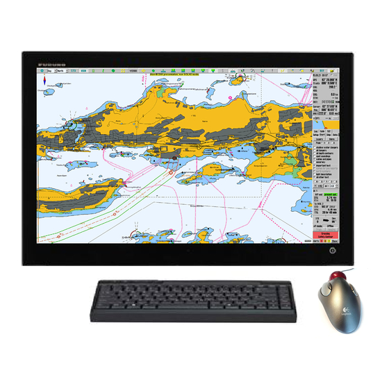
Summary of Contents for Furuno TECDIS
- Page 1 TECDIS Installation Manual Page 0 Installation Manual A fully type approved Electronic Chart and Display Information System (ECDIS), Software edition: 4.7.1 Manual edition: 2.1 certified by DNV.
- Page 2 TECDIS Installation Manual Page 1 The PC Main board is equipped with a litium battery. The lithium battery should be replaced only in the factory. There is a danger of explosion if the wrong type of battery is used for replacement.
-
Page 3: Table Of Contents
TECDIS Installation Manual Page 2 GENERAL INTRODUCTION TO THE INSTALLATION MANUAL ......... 4 STANDARDS COMPLIANCE ....................5 EQUIPMENT LISTS: ........................6 INSTALLATION OVERVIEW....................7 SPECIFICATIONS: ........................8 CHAPTER 1: MOUNTING ....................... 12 1.1 M ........................ - Page 4 TECDIS Installation Manual Page 3 3.5.5 M ..................47 ONITOR ALIBRATION AND 3.6 L ..........................48 ICENSING 3.6.1 TECDIS ........................48 LICENSE 3.6.2 C-MAP L ........................49 ICENSE 3.6.3 D ......................49 YNAMIC ICENSING ...
-
Page 5: General Introduction To The Installation Manual
Page 4 General introduction to the installation manual This manual is describing the procedure to ensure a proper and safe installation of our TECDIS onboard a vessel. Please read carefully this manual before you start up the commissioning of the TECDIS. -
Page 6: Standards Compliance
• IMO Resolution A.817(19) as amended by MSC.64(67) Annex 5 and by MSC.86/70) Annex 4 • IMO Resolution A.694(17). For a current overview of software versions, standards compliance and instructions for updating TECDIS software to comply with new standards and regulations, refer to the following web site: http://www.telko.no/site/support/tecdis/compliance... -
Page 7: Equipment Lists
TECDIS Installation Manual Page 6 Equipment lists: Standard Supply Name Type Remarks Computer HT405P4 TEL-A1 1,9 m power cable Monitor JH 20T17 MMD 2,0 m video cable 1,9 m power cable TECDIS keyboard BTC-5100C 1,3 m cable TECDIS mouse Mouse-trak B-MPIND-... -
Page 8: Installation Overview
TECDIS Installation Manual Page 7 Installation Overview... -
Page 9: Specifications
TECDIS Installation Manual Page 8 Specifications: Processor HT 405P4 TEL-A1: Monitor JH 20T17 MMD: • 20,1 inch viewable image size • 4U – 19” Rack Mount Computer • A-Si (Thin Film Transistor) Active matrix, • Intel Pentium 4 – 3.4 GHz (S775) •... - Page 10 TECDIS Installation Manual Page 9 Mouse-Trak B-MPIND-XROHS: Functional Specifications: Resolution: 192 to 576 pulses per revolution of the ball. Input Switches: Three (3) Interface: IBM PS/2 Connector: 6-Pin Mini-DIN Male Pin Assignments: Pin 1 = PS/2 Data Pin 2 = NC...
- Page 11 TECDIS Installation Manual Page 10 Speaker HP-6/HPS-6: Material/Color Polyamide UL94 V0 / RAL 7035 Mounting Bracket Termination Cable,0,5m Weight 0.5 kg IP-rating (UL (-) 67 Equivalent) Max. / min. amb. 90°C / -40 °C Temp Rated / max. power 6W / 15W...
- Page 12 32 digital inputs 32 analog input (24 x +/- 10VDC and 8 x 4-20mA ) Outputs: RS422 output ar baudrate 4800,n,8,1 to Furuno VDR Ethernet TCP/IP serverport at 192.168.0.60 : 2000 Ethernet UDP/IP broadcast at 0.0.0.0 : 2100 The placement of the modules in the box are.
-
Page 13: Chapter 1: Mounting
TECDIS Installation Manual Page 12 Chapter 1: Mounting 1.1 Monitor Unit The monitor unit can be flush mounted in a console panel, or mounted on desktop using optional accessories. When selecting a mounting location, keep in mind the following points: 1. - Page 14 TECDIS Installation Manual Page 13 Outline dimensions for JH 20T17 MMD: Dimensions might be shown with or without decimals and indicated as mm [inches]. Tolerance on drawings is +/- 1mm. For accurate measurements, check relevant DWG file, as obtainable from http://www.hatteland-display.com/maritime_line_displays_series1.php.
- Page 15 TECDIS Installation Manual Page 14 Outline dimensions for JH 19T14 MMD: Dimensions might be shown with or without decimals and indicated as mm [inches]. Tolerance on drawings is +/- 1mm. For accurate measurements, check relevant DWG file, as obtainable from http://www.hatteland-display.com/maritime_line_displays_series1.php.
- Page 16 TECDIS Installation Manual Page 15 Outline dimensions for JH 23T12 MMD: Dimensions might be shown with or without decimals and indicated as mm [inches]. Tolerance on drawings is +/- 1mm. For accurate measurements, check relevant DWG file, as obtainable from http://www.hatteland-display.com/maritime_line_displays_series1.php.
-
Page 17: Processor Unit
TECDIS Installation Manual Page 16 1.2 Processor Unit The processor unit can be mounted inside on bridge console or other suitable space on the bridge. When selecting a mounting location, keep in mind the following points: 1. Select a location where vibrations are down to a minimum, try to avoid vibrations by adding strength to console where the processor is about to be installed. - Page 18 TECDIS Installation Manual Page 17 Outline dimensions for HT 405P4 TEL-A1: All figures in mm.
-
Page 19: Control Unit Furuno Rcu-018
Flush mounting Use the optional flush mount kit Furuno FP03-09870 to mount the control unit to a console panel. Name: Flush mount kit Type: Furuno FP03-09870 Code No.: 008-535-630... - Page 20 TECDIS Installation Manual Page 19 Furuno RCU-018 Control Unit outline (Desktop mount) All figures in mm.
- Page 21 TECDIS Installation Manual Page 20 Furuno RCU-018 Control Unit outline (Desktop mount with bracket) All figures in mm...
- Page 22 TECDIS Installation Manual Page 21 Furuno RCU-018 Control Unit outline (Flush mount)
-
Page 23: Keyboard And Trackball
TECDIS Installation Manual Page 22 1.4 Keyboard and trackball Keyboard and trackball must be mounted close together, such that both can be operated simultaneously by one person. When selecting a mounting location, keep in mind the following points: 1. Select a location where the control unit can be operated conveniently. -
Page 24: Additional Units
TECDIS Installation Manual Page 23 Outline dimensions for Trackball: 202 mm 101 mm 1.5 Additional units When mounting additional units such as, loudspeaker, analogue alarm units, MOXA interface and other peripheral equipment, general considerations should be taken to ensure proper functions of respective equipment. - Page 25 TECDIS Installation Manual Page 24 Outline dimensions for alarm interface TEA-01: Length: 125 mm Width: 55 mm Heigth: 40 mm Cable length: 1400 mm Outline dimensions for loudspeaker DNH HP6, with bracett: Loudspeaker cable length is 500 mm.
- Page 26 TECDIS Installation Manual Page 25 Outline dimensions for loudspeaker DNH HPS6, for flush mount: Loudspeaker cable length is 500 mm.
- Page 27 TECDIS Installation Manual Page 26 Outline dimensions for analog interface connection/distribution box, TA3232-1: Length: 500 mm Width: 500 mm Heigth: 210 mm...
- Page 28 TECDIS Installation Manual Page 27 Outline dimensions for MOXA RS-422 interface box, MOXA OPT8F: Dimensions for box: 247 x 108 x 35 mm DB-62 cable length: 1500 mm...
-
Page 29: Track Control: Anschütz Np 2025 Plus
• Speed sensor • Alarm System for transfer of back-up navigator alarm TECDIS and the NP 2025 PLUS must be supplied with the same set of heading and log sensor inputs. On vessels where the steering system does not provide a “freeze rudder function” and maintained voltage is required for maintaining rudder angle, provisions must be made on installation of Anschütz NP 2025 PLUS to maintain steering voltage output on power loss to... -
Page 30: Naut Aw: Gyro Sensor Input Requirements
TECDIS Installation Manual Page 29 1.7 NAUT AW: Gyro Sensor Input Requirements For vessels with class notation NAUT AW, the gyro sensor input to TECDIS AW must satisfy the following requirements: The GAS must be supplied with a redundant gyro system including: 1.1. -
Page 31: Chapter 2: Wiring And Signal Distribution
TECDIS Installation Manual Page 30 Chapter 2: Wiring and signal distribution On the following pages wiring and signal distribution diagrams are shown. Signal distribution diagram is an indication of possible means of signal distribution. During installation actual need for signal distribution must be verified by installer, depending on signals available and actual hardware installation on the specific vessel. -
Page 32: Wiring Diagram (Ht 405P4 Tel-A1)
TECDIS Installation Manual Page 31 2.1 Wiring diagram (HT 405P4 TEL-A1):... -
Page 33: Signal Distribution Diagram (Internal Data Flow)
TECDIS Installation Manual Page 32 2.2 Signal distribution diagram (internal data flow):... -
Page 34: Processor Connectors, Ht 405P4 Tel-A1
• If optional speaker connectors HT00072 Opt-A1 are used, LINE OUT and LINE IN are to be connected using the supplied cable. • Lan connector GBLAN1 is to be used when connecting the TECDIS unit to other TECDIS units, T Adapter or Furuno FAR-2xx7 series radar. -
Page 35: Ethernet Connectors And Cable
TECDIS Installation Manual Page 34 2.4 Ethernet connectors and cable... -
Page 36: Other Connectors
TECDIS Installation Manual Page 35 2.5 Other connectors... -
Page 37: Chapter 3: Parameter Setup
TECDIS. When this service key is connected to the chart plotter, the chart plotter will not be turned off when you exit TECDIS and you will be able to work in Windows (service mode) and open the Setup program by double clicking on the Setup icon on the desktop. When service mode is available, a text indication is shown in the lower right corner of the chart. -
Page 38: Inputs
4. Optionally (but recommended) enter a description identifying the sensor as a GPS in the “Sensor Description” field. If the sensor signal is lost while the TECDIS is in operation, an alarm will be sounded. The alarm message will indicate the type of sensor lost as well as what port it is connected to and the sensor description you enter in this field. -
Page 39: Outputs
3.2.3 Outputs In this area you can select which NMEA sentences you want TECDIS to output. In order to send a NMEA sentence type on a COM port, put a check mark in the box at the intersection of the desired sentence type row and COM port column. -
Page 40: Supported Nmea Sentences
Course Over Ground and Ground Speed Receive Relative (Apparent) Wind Speed and Angle Receive Waypoint Location Send / Receive Time and date Receive NOTE: TECDIS also supports a number of proprietary protocols for specific application areas. Contact your TECDIS supplier for details. - Page 41 TECDIS Installation Manual Page 40 When a given sensor provides more than one of the supported NMEA sentences, the highest ranking option from the following lists (as applicable) should be used: Position 1. $??GNS GNSS fix data 2. $??GGA GPS fix data 3.
-
Page 42: Specification
(objects, tracks, routes) to the second unit. (See chapter 3.8 Route Synchronization for details). NOTE: If the TECDIS unit is not to be connected to a second TECDIS unit, this value should be set to “0.0.0.0”. For any other value in this field, TECDIS will generate an... -
Page 43: Save And Restore Setup Default Values
He can then keep this file in his personal register of TECDIS installations. The following files should be copied: • C:\Program files\TECDIS\dta4.setup • C:\Program files\TECDIS\Telchart.ini NOTE: When a Service Key is present when TECDIS Setup is closed, a backup copy of the files specified above are automatically copied to the Service Key. -
Page 44: Tecdis Nmea And Tcp/Ip Server
Page 43 3.4 TECDIS NMEA and TCP/IP server TECDIS NMEA and TRP/IP server allows distribution of selected comport data out through a TCP/IP network. This way one sensor can be shared by multiple users in a TCP/IP network. As shown above, “HDT sentence”, is received on comport 3 and is retransmitted on port 2003 through TCP/IP address 192.168.0.113. -
Page 45: Chart Installation / Misc
TECDIS Installation Manual Page 44 3.5 Chart Installation / Misc 3.5.1 Install, update or remove chart databases By clicking “Copy”, a new area with an overview of installed chart databases is opened. Insert the CD for the chart database that is to be operated on and select the CD-ROM drive from the drop down menu below the database list. -
Page 46: Enter Vessel Information
TECDIS Installation Manual Page 45 If a CD is not available for the chart database (As would be the case for databases containing imported S57 data), these databases can be selected for modification by choosing a drive other than the CD-ROM drive from the drive drop down menu. -
Page 47: Send Registration
TECDIS Installation Manual Page 46 3.5.3 Send registration When the vessel information has been entered and stored, the option to send registration will be enabled on the main area of this part of the Setup program. If “Send on Diskette” is selected, the registration file will be saved to an inserted diskette. -
Page 48: Monitor Calibration And Test
“Manual Calibration: Load Calibration File…” button and selecting the correct calibration file matching the monitor. If such a file cannot be located, this can be obtained from your TECDIS support provider. Monitor Calibration Status: Indicates the current status of monitor calibration. The possible... -
Page 49: Licensing
TECDIS Installation Manual Page 48 3.6 Licensing 3.6.1 TECDIS license By clicking “Show / edit license” information about the current system license is shown as illustrated below. This information includes the license number and version information, and a list of installed optional components in blue in the right part of the area. In order to activate additional optional components, a password for this should be entered in the “Password”... -
Page 50: C-Map License
In this area, it is also possible to get a list of licenses that are expired and no longer valid (“Get expired licenses”), to see a list of all valid licenses (“Licenses list”) and to generate an order file for new licenses (“License order”). 3.6.3 Dynamic Licensing For information regarding dynamic chart licensing, refer to “TECDIS 4.7.1: New Features Guide”. -
Page 51: Track Control
Control can be set. Refer to Raytheon Anschütz AP2025 PLUS Installation Manual for installation and configuration of the autopilot. NB: The autopilot and TECDIS must be supplied with the same heading and log sensor inputs! 3.7.1. Starting Requirements The values in this area specify the conditions needed before Track Control mode can be activated. -
Page 52: Default Values New Route
This setting controls the distance allowed between the two position sensors before an alarm is generated, expressed in hundredths of a nautical mile. If the distance between the positions reported by the two position sensors is larger than this value, an alarm is generated in TECDIS. -
Page 53: Route Synchronization
When the basic route synchronization method is in use and a route is activated on either of the TECDIS units, a backup copy of the route is transferred to the other TECDIS. This backup is not automatically included in the route list on the receiving TECDIS unit, but it can be imported when needed. - Page 54 1. Verify that the requirements for this feature listed above are met. 2. If routes are present on the TECDIS units, select one unit where all routes will be kept and one TECDIS unit where all routes will be removed.
-
Page 55: Chapter 4: Operational System Settings
PC Speaker or Keyboard in TECDIS Setup) Auxiliary 10. Hide/unhide tool tip. Ship draught: minimum and maximum ship draught is defined in the setup program. When TECDIS starts, the maximum draught is used as default, but this can changed in the setup menu folder. -
Page 56: Nmea Data Inputs
This is only a information window. Changes have to be made in TECDIS Setup. (see chapter 3). Position fixing: Displays 2 sources for positioning. Primary and secondary can be selected. Primary and secondary can be displayed simultaneously on the chart display. -
Page 57: Operational Parameters For Ais
“Show danger CPA” allows display of the CPA graphically in the chart. If “Allow Standby Mode” is selected in TECDIS Setup (See chapter 3.3), it is possible to disable CPA alarms by unselecting “Raise CPA alarm”. A prominent warning is displayed when CPA... -
Page 58: Chart Library
TECDIS Installation Manual Page 57 4.4 Chart library Chart library displays an overview of all chart in a database. Selecting a database from the drop down menu a list with all charts in the database appears, sorted by publisher. Highlight a chart in the list to display further information (middle field). -
Page 59: Import Of S57 Data
TECDIS Installation Manual Page 58 Remove dataset: If a database contains imported S57 data is selected in the drop down menu, the button” Remove Dataset” will delete selected chart. 4.5 Import of S57 data NB: When two ECDIS machines are connected, make sure to make the same updates in the second ECDIS. -
Page 60: Import Of S-63 Chart Data
TECDIS Installation Manual Page 59 If errors are discovered a ”S57 Import ERROR report” is shown. The error report contains name of import file and whether the error are critical or non-critical. Files including critical errors are not imported. If non-critical errors occurs, files can be imported or excluded by pressing ”continue”... -
Page 61: Chapter 5: Miscellaneous
Chapter 5: Miscellaneous 5.1 Error Messages TECDIS includes automatic error detection in most functions. If it is possible, corrective measures will be taken without requiring operator intervention. In case of critical errors, the operator is notified. In addition to the possible error situations listed here, both the Windows operating system and support routines may in some instances display error messages not listed. - Page 62 TECDIS Installation Manual Page 61 190=Read of file length failed Error in license dongle. 191=File number out of bounds Error in license dongle. 192=Cmap init error License dongle not C-Map approved. 193=Init has not been called Error in communication with license dongle.
-
Page 63: Monitor Calibration
TECDIS Installation Manual Page 62 5.2. Monitor Calibration All information in electronic chart displays must be highly visible. To ensure this monitor must be calibrated to display correct colors. This is very important, specially for night palettes, when monitor is dimmed. - Page 64 TECDIS Installation Manual Page 63 This page is intentionally left blank...
-
Page 65: Chapter 6: Checklists Regarding Installation
(save setup default values) on main and back-up TECDIS. Verify that installed charts have been correctly installed on both main and backup TECDIS (if installed), and that charts license matches. Unplug TECDIS USB-key, restart TECDIS to verify it starts up in normal mode (chart program starts automatically) and boat symbol and sensor data are displayed. - Page 66 TECDIS license # Back-up Vessel Name / ID: Date of installation: Name of technician: Checklist performed (Sign): This checklist shall be filled in and signed for all TECDIS installations, in order to verify proper installation of the ECDIS system onboard.
-
Page 67: Checklist Prior To Completion Of Tecdis Tcs And Tecdis Aw Installation
• A speed sensor □Good □NG □N/A TECDIS 1: □Good □NG □N/A Alarm system Verify that TECDIS is connected to a separate alarm system. TECDIS 2: □Good □NG □N/A TECDIS 1: □Good □NG □N/A System status Check that no alarms/warnings are pending in alarm window. - Page 68 TECDIS 2: □Good □NG □N/A Verify that TECDIS handle different functions like; 1. Disconnect position sensors and observe dead reckoning performance, verify that alarm is given: pos sensor ½ lost. 2. Activate track dialog and set past tracks visible by clicking on “show”...
- Page 69 20 degrees below Gyro heading. 2,Confirm the actual rudder angle by rudder angle indicator. 1. Change operating mode from hand to heading control at Track Control TECDIS , verify that correct mode is indicated on TECDIS and conning monitor also. □Good □NG □N/A Function 2.
- Page 70 WP pre-warning and WP alarm on ECDIS is not acknowledged. 3. Set alarm for gyro mismatch to minimum in TECDIS Setup program. Wait for alarm to be raised. 4. Activate route and use “Heading Control” mode on autopilot.
- Page 71 TECDIS Installation Manual Page 70 Example of route for Track Control testing WPT 3: 135 deg turn port, WPT 5: 135 deg turn starboard (both with minimum radius*) WPT 4: 60 deg turn port, WPT 7: 60 deg turn starboard (both with 2 NM radius)
- Page 72 TECDIS Installation Manual Page 71 ECDIS Scheduled Track Course 90 deg AP Scheduled Course 90 deg Wheel Over Point WP Approach alarm 30 sec before wop Pre-Warning alarm 120sec before wop Trial Speed Approach run Ship start turn from wheel over point with 90...
- Page 73 TECDIS Installation Manual Page 72 Fail to Safe Properties Item Fail Track Control (TCS) Test Result Position sensor antennas When either of position sensor Remove No.1 to be blinded off. acquisition stops, TCS emits alarm but position sensor continues to function utilizing acquired...
- Page 74 Vessel Name / ID: Date of installation: Name of technician: Checklist performed (Sign): The checklist in section 6.3 shall be filled in and signed for all TECDIS AW installations, in order to verify proper installation of the ECDIS system onboard.
-
Page 75: Installation Notes
TECDIS Installation Manual Page 74 6.4 Installation Notes... - Page 76 TECDIS Installation Manual Page 75...
-
Page 77: Revision History
• Installation Overview illustration updated • Specifications updated • Updated mounting section • Added mounting Chapter 1.3 Control Unit Furuno RCU-018 • Added Chapter 2.1, HT405P4 Wiring diagram • Added Chapter 2.3, Processor connectors, HT405P4 TEL-A1 • Renumbered chapters following 2.1 Revision 1.6 (30.04.2007) - Page 78 Revision 1.9 (16.04.2008) • Changed heading for section 6.2 to include TECDIS AW • Added new section 6.3 for additional TECDIS AW requirements checklist • Old section 6.3 and 6.4 are now section 6.4 and 6.5 • New section 1.7 for NAUT AW gyro sensor input requirements Revision 2.0 (20.01.2009)
- Page 79 TECDIS Installation Manual Page 78 This page is intentionally left blank...
- Page 80 TECDIS Installation Manual Page 79 M/V BOURBON TOPAZ M/F JULSUND Head Office, Aalesund Branch office, Deep Sea Furuno Norge AS Furuno Norge AS Visitor address/Shipment address: Visitor address/Shipment address: Sjømannsveien 19 Øvre Fyllingsvei 81 N-6008 Aalesund N-5162 Laksevåg Postal address:...
Need help?
Do you have a question about the TECDIS and is the answer not in the manual?
Questions and answers