Furuno FE-700 Operator's Manual
Navigational echo sounder
Hide thumbs
Also See for FE-700:
- Installation manual (61 pages) ,
- Service manual (58 pages) ,
- Software manual (8 pages)
Table of Contents
Advertisement
Advertisement
Table of Contents
Troubleshooting

Related Manuals for Furuno FE-700


Summary of Contents for Furuno FE-700
- Page 1 Back OPERATOR'S MANUAL NAVIGATIONAL ECHO SOUNDER FE-700 MODEL www.furuno.co.jp...
- Page 2 *00080890817* *00080890817* *00080890817* *00080890817*...
-
Page 3: Important Notices
How to discard a used battery Some FURUNO products have a battery(ies). To see if your product has a battery(ies), see the chapter on Maintenance. Follow the instructions below if a battery(ies) is used. In the European Union The crossed-out trash can symbol indicates that all types of batteries must not be discarded in standard trash, or at a trash site. - Page 4 WARNING LABEL Continued use of the equipment can cause A warning label is attached to the equip- fire or electrical shock. Contact a FURUNO ment. Do not remove the label. If the agent for service. label is missing or illegible, contact a FURUNO agent or dealer.
-
Page 5: Table Of Contents
CONTENTS 3.3 System Menu 2 ........12 FOREWORD ......... iv 3.4 System Menu 3 ........13 A Word to FE-700 Owners......iv 4 ECHO QUALITY SETTING..... 14 Features............iv 4.1 Demonstration Display ......14 SYSTEM CONFIGURATION ....v 4.2 Bottom Level ........14 SPECIFICATIONS OF FE-700 .. -
Page 6: Foreword
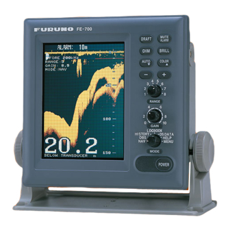
FOREWORD Features A Word to FE-700 Owners The FURUNO FE-700 is comprised of display Thank you for purchasing this navigational echo unit and transducer unit. Echo sounding data is sounder. We are confident you will discover why displayed on the bright 6.5-inch color TFT (Thin FURUNO has become synonymous with quality Film Transistor) LCD display. -
Page 7: System Configuration
FE-700 system configuration PRINCIPLE OF OPERATION The FE-700 uses ultrasonic pulses to detect the seabed and other underwater objects. The display unit contains all basic electric circuits and logic processor. Electrical pulses are converted into acoustical energy in the transducer fitted on the ship’s hull. The processor measures the time of pulses travelling between the seabed and transducer and displays the water depths in the graphical form or other forms. - Page 8 FURUNO FE-700 SPECIFICATIONS OF NAVIGATIONAL ECHO SOUNDER FE-700 GENERAL Transmit frequency 50 kHz, 200 kHz, or 50/200 kHz alternating transmit Output power 600 Wrms Beam width 50B-6B (50 kHz): 35°, 200B-8B (200 kHz): 6° Basic display range Range Unit Meter...
- Page 9 FURUNO FE-700 1 hour at 5 sec Interval, 12 hours at 1 minute interval and 24 hours at 2 minutes interval *: External navigational sensor required. DIGITAL DEPTH INDICATOR Display 4.5-inch monochrome LCD Depth indication **.* m (less than 100m), **** m (100 m or more)
-
Page 10: Operation
1 OPERATION 1.1 Control Description All operation of the FE-700 is carried out with the controls on the front panel of the display unit. Rotary controls respond immediately to your command but some touch keys require the successive operation. •... -
Page 11: Indications, Markers
1.2 Indications, Markers Display mode Gain setting Transducer in use Range setting Alarm Auto Range scale Alarm mode setting ALARM 15m ALARM 15m FORE 50kHz FORE 50kHz RANGE: 4 GAIN: 5.5 MODE: NAV Depth alarm line Depth LOGBOOK HISTORY OS DATA HELP Depth unit MENU... -
Page 12: Turning On/Off
1.3 Turning On/Off 1.4 Tone and Brilliance 1. Turning on: Press the POWER Switch. 1. Press the BRILL key. The tone and brilliance Self-test starts, showing the condition of the setting window appears. logic circuits. The program number is displayed. BRILL: 8 ROM: OK LOW-... -
Page 13: Display Mode
1.6 Display Mode CAUTION The Mode Selector choose the display mode DBS is not a water clearance below among NAV, DBS (depth below surface), keel. HISTORY, LOGBOOK, OS DATA, HELP, and Do not use this mode in shallow MENU. waters to avoid grounding. 1.6.1 NAV mode 1.6.3 HISTORY mode The depth from the transducer to the seabed... -
Page 14: Os Data Mode
1.6.4 LOGBOOK mode 1.6.5 OS DATA mode The LOGBOOK shows time, depth and own ship This display mode indicates own ship position, position in tabular form in a pop-up window. The GPS-derived course and speed, and time and logging is selected with the INTERVAL option on depth in digital form. - Page 15 Enlarging data of interest 1.6.7 MENU display You can enlarge one of the data indications as The menu provides functions which normally do follows: not require frequent adjustment. For details see 1. Press the [▲] or [▼] key to select the data Chapter 2.
-
Page 16: Range Scale
• 1.7 Range Scale Clutter level (on the menu), which works as a threshold control to suppress overall noise, is If the depth goes out of the correct display area, automatically adjusted. increase or decrease the range until the seabed Note: The AUTO MODE is cancelled whenever appears near the center of the screen. -
Page 17: Shallow Depth Alarm
1.12 Draft Monochrome (amber) is the default setting. The Strata display contains multiple colors depending It is necessary to set the draft to use the DBS on the reflectivity from underwater objects of the display mode, which shows depth below surface. sounding pulses. -
Page 18: Menu Operation
2 MENU OPERATION 2.1 Menu Overview 2.2 Suppressing Low Level Noise The menu has several functions for advanced operation. Light-blue dots may appear overall screen. This is mainly due to dirty water or noise. This noise 1. Select MENU with the MODE Selector. can be suppressed by adjusting CLUTTER (in CLUTTER reality, Threshold of the amplifier). -
Page 19: Picture Advance
2.4 Picture Advance 3/60 TIME DEPTH The picture advance speed determines how 11:00:00 47.5 36°55.012’N quickly the vertical scan lines run across the 135°23.123’E screen. 11:01:00 47.5 36°55.012’N 135°23.123’E 1. Select MENU with the MODE Selector. 11:02:00 47.5 36°55.013’N 135°23.123’E 2. -
Page 20: System Menu
3 SYSTEM MENU 3.1 System Menu The system menu 1 appears. 5. With the cursor selecting MENU SELECT, The system menu should be set just after operate the [-] or [+] key to select system installation and is not always necessary to be menu desired;... -
Page 21: System Menu 1
(0∼59) mode is switched. 01 AUG 2009 00:00:00 INTERFACE: Selects I/O signal format between the FE-700 and external equipment; IEC format ▼▲: To select item “1:95” (1995 version) or “1:98” (1998 version), or - +: To set option NMEA format. Default setting is IEC “1:98”. -
Page 22: System Menu 3
TIME DIFFERENCE: Selects auto (UTC) or 3.4 System Menu 3 manual. Auto uses the time difference in ZDA RANGE 1- 8: Activates or deactivates specific (IEC 61162-1). In manual, it is necessary to range scales. Default ranges are 5, 10, 20, 40, enter the time difference in hours and minutes. -
Page 23: Echo Quality Setting
FE-700 works. CAUTION 1. Turn off the equipment. If the level is set too low, the FE-700 2. Press the POWER Switch while pressing any may not be able to distinguish the key. Release the key when the following... -
Page 24: Tvg Level
Note: Do not switch transducer (frequency) at the EX-8 when setting the TVG Level menu. If it is necessary to set TVG level for a different frequency, turn off the FE-700, switch transducer at EX-8 and then turn on the FE-700 again. -
Page 25: Operation Of Digital Depth
5 OPERATION OF DIGITAL DEPTH INDICATOR FE-720 (OPTION) 2. Press [ ] or [ ] until the required value is reached. The range of adjustment is from Omnipad 0 (Min.) to 63 (Max.). The default is 48. 3. Press the ENT key to set. Note: The contrast is automatically set to the MENU default when you turn on the power. -
Page 26: Menu Operation
5.2 Menu Operation 5.2.2 Selecting language The language in use on the screen is either 5.2.1 Dimmer control English or Japanese. 1. Press the MENU key to display main menu. The dimmer is controlled either with the DIM key, 2. Press [▲] or [▼] to select the or the optional Dimmer Controller. -
Page 27: Diagnosis
4. With YES selected, press the ENT key to 5.2.4 Alarm start the test. The equipment tests the ROM You can set turn alarm on or off. In the ON mode, and RAM, displaying the results as OK or if the main display unit activates the alarm, the NG (No Good). -
Page 28: Maintenance, Troubleshooting
6 MAINTENANCE, TROUBLESHOOTING 6.3 Transducer Maintenance WARNING Marine life on the transducer face will result in a gradual decrease in sensitivity. Check the Do not open the cover. transducer face for cleanliness each time the There are no user-serviceable parts inside. ship is dry-docked. -
Page 29: Troubleshooting
6.5 Troubleshooting The table below provides simple troubleshooting procedures which you may follow to restore normal operation. If you cannot restore normal operation, contact your dealer. SYMPTOM PROBABLE CAUSES REMEDY No picture; no reading Low power supply Check the supply voltage. measure Fuse blown Replace the fuse. -
Page 30: Diagnostic Test
6.6 Diagnostic Test 6.7 Test Pattern The diagnostic test checks the ROM, RAM, color The test pattern is used to check color bar and keyboard for proper operation. performance. 1. Turn on the power while pressing any key. 1. Turn on the POWER SWITCH while pressing Release the keys when the following display any key. -
Page 31: Clearing The Memory
6.8 Clearing the Memory All menu settings can be cleared to start afresh. All default menu settings are restored when the memory is cleared. For your reference all default settings are shown in the menu tree at the end of this manual. -
Page 32: Menu Tree
7 MENU TREE CLUTTER (AUTO, 0-16) MENU INTERFERENCE REJECT (OFF, IR1, IR2, IR3) PICTURE ADVANCE (SLOW, FAST) TREND INDICATOR (ON, OFF) INTERVAL (5S, 1MIN, 2MIN) ECHO XDR (FORE, AFT) HISTORY XDR (FORE, AFT) GO TO SYSTEM MENU? (NO, YES) MENU SELECT (1, 2, 3) SYSTEM MENU 1 DEPTH UNIT (m, ft, fa) SPEED UNIT (kt, MPH, km/h) -
Page 33: Digital Interface (Iec 61162-1 Edition 2)
DIGITAL INTERFACE (IEC 61162-1 EDITION 2) 1. I/O Sentences Input sentences of channel 1 (NAV IN) RMA, RMC, GLL, GGA, VTG, ZDA Output sentences of channel 2 (NAV OUT) DBT, DPT, DBS (NMEA 0183), DBK (NMEA 0183) Transmission interval 1 s for any sentence Data transmission Data is transmitted in serial asynchronous form in accordance with the standard referenced in 2.1 of IEC 61162-1. - Page 34 2. Schematic Diagrams NAV IN port (listener) FE-702 FE-701 02P6281 02P6280 02P6283 MJ-A10SRMD B10B-XH-A 236-410M1-10 XHP-10 MJ-A10SRMD 00-9072-230-101-883 00-900-9072-901-883 NAV IN PC400 RD1_A RD1_B 1SS226 Load requirements as listener Isolation: Optocoupler Input Impedance: 560 ohms Max. Voltage: ±15V NAV OUT ports FE-702 FE-701 02P6280...
- Page 35 3. Sentence Description DPT - Depth $--DPT,x.x,x.x,x.x*hh<CR><LF> | +----- 4 +--------- 3 +------------ 2 +---------------- 1 1. Water depth relative to trancsducer, in meters 2. Offset from transeducer, in meters(see notes 1 and 2) 3. Maximum range scale in use 4.
- Page 36 GLL - Geographic position - latitude/longitude $--GLL,llll.lll,a,yyyyy.yyy,a,hhmmss.ss,A,a*hh<CR><LF> | | | | | +------- 6 | +--------- 5 +----------- 4 +---------------- 3 +------+----------------------- 2 +---+----------------------------------- 1 1. Latitude, N/S 2. Longitude, E/W 3. UTC of position 4. Status: A=data valid, V=data invalid 5.
- Page 37 GGA - Global positioning system (GPS) fix data $--GGA,hhmmss.ss,llll.lll,a,yyyyy.yyy,a,x,xx,x.x,x.x,M,x.x,M,x.x,xxxx*hh<CR><LF> | | | | | | +-- 11 | | | +---- 10 | | | | +--------- 9 | | | | +---+------------ 8 | | | +---+------------------ 7 | | | +------------------------- 6 | | +---------------------------- 5 | +------------------------------- 4...
- Page 38 RMA - Recommended minimum specific LORAN-C data $--RMA,A,llll.lll,a,yyyyy.yy,a,x.x,x.x,x.x,x.x,x.x,a,a*hh<CR><LF> | | | | | +------- 10 | +--------- 9 | +---+----------- 8 +------------------ 7 +---------------------- 6 +-------------------------- 5 | +------------------------------ 4 +----+--------------------------------- 3 +---+-------------------------------------------- 2 +------------------------------------------------------- 1 1. Status: A=data valid, V=blink, cycle or SNR warning 2.
- Page 39 RMC - Recommended specific GPS/TRANSIT data $--RMC,hhmmss.ss,A,llll.lll,a,yyyyy.yyy,a,x.x,x.x,xxxxxx,x.x,a,a*hh<CR><LF> | | | | | | | +--- 10 | | +----- 9 +--+------- 8 +--------------- 7 | +--------------------- 6 | +------------------------- 5 +---+---------------------------- 4 +---+---------------------------------------- 3 +--------------------------------------------------- 2 +---------------------------------------------------------- 1 1. UTC of position fix 2.
- Page 40 VTG- Course over ground and ground speed $--VTG,x.x,T,x.x,M,x.x,N,x.x,K,a*hh<CR><LF> | | | | | | | +------- 6 | | +--------- 5 +--+----------- 4 | | +--+----------------- 3 | | +--+----------------------- 2 +--+----------------------------- 1 1. Course over ground, degrees true 2. Course over ground, degrees magnetic 3.
-
Page 41: Parts Location, Parts List
9 PARTS LOCATION, PARTS LIST MAIN BOARD 02P6280 ANLG 02P6281 HEATSINK INTERFACE PNL 02P6250 MEM 02P6282 (Beneath) MAIN DISPLAY UNIT FE-701, INSIDE VIEW (SHIELD COVER REMOVED) ISOLATION TRANSFORMER CON 02P6283 DISTRIBUTION BOX FE-702, INSIDE VIEW... - Page 42 FURUNO Model FE-700 Unit DISPLAY UNIT FE-701 DISTRIBUTION BOX FE-702 ELECTRICAL PARTS LIST Ref.Dwg. Page Jan-99 Blk.No. SYMBOL TYPE CODE No. REMARKS SHIPPABLE ASSEMBLY PRINTED CIRCUIT BOARD 02P6281,ANLG 001-229-240 FE-701 02P6282,MEM 001-229-220 FE-701 02P6283,CONE 001-229-030 FE-702 02P6280,MAIN 001-229-190 FE-701 PANEL ASSEMBLY...
-
Page 43: Declaration Of Conformity
(Address) declare under our sole responsibility that the product Navigational echo sounder type FE-700 consisting of Display unit FE-701, Distribution box FE-702, Matching box MB-502 (50 kHz) or MB-504 (200 kHz), Transducer 50B-6B (50 kHz) or 200B-8B (200 kHz), Junction box JIS F8821-1 and...
Need help?
Do you have a question about the FE-700 and is the answer not in the manual?
Questions and answers