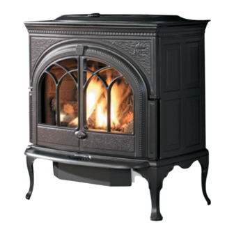
Jøtul GF 600 DV II Firelight Installation And Operation Instructions Manual
Direct vent gas stove
Hide thumbs
Also See for GF 600 DV II Firelight:
- Installation and operation instructions manual (28 pages) ,
- Installation and operation instructions manual (28 pages)
Table of Contents
Advertisement
WARNING: If the information in these
instructions is not followed exactly, a fire
or explosion may result causing property
damage, personal injury or loss of life.
– Do not store or use gasoline or other
flammable vapors and liquids in the vicinity
of this or any other appliance.
– WHAT TO DO IF YOU SMELL GAS
• Do not try to light any appliance.
• Do not touch any electrical switch; do not
use any phone in your building.
• Immediately call your gas supplier from a
neighbor's phone. Follow the gas supplier's
instructions.
• If you cannot reach your gas supplier, call
the fire department.
– Installation and service must be performed
by a qualified installer, service agency or the
gas supplier.
– In the Commonwealth of Massachusetts,
a carbon monoxide (CO) detector shall be
installed in the same room as the appliance.
This appliance may be installed in an aftermarket,
permanently located, manufactured home or mobile
home, where not prohibited by local codes.
This appliance is only for use with the types of gas
indicated on the rating plate. A conversion kit is
supplied with the appliance.
INSTALLER: Leave this manual with the appliance.
CONSUMER: Retain this manual for future reference.
Installation and
Operation Instructions
ATTENTION : CES INSTRUCTIONS DOIVENT
DEMUERER AVEC LE PROPRIÉTERE D'UNE
MAISON.
AVERTISSEMENT: Assurez-vous de bien
suivreles instructions données dans cette
notice pour réduire auninimum le risque
d'incendie ou d'explosion ou pour éviter
tout dommage matériel, toute blessure ou la
mort.
– Ne pas entreposer ni utiliser d'essence ni
d'autres vapeurs ou liquides inflammables
dans le voisinage de cet appareil ou de tout
autre appareil.
– QUE FAIRE SI VOUS SENTEZ UNE ODEUR DE GAZ:
• Ne pas tenter d'allumer l'appareil.
• Ne touchez à aucum interrupteur. Ne
pas vous servir des téléphones se trouvant
dans le bâtiment où vous trouvez.
• Appelez immédiatement votre
fournisseur de gaz depuis un voisin.
Suivez les instructions du fournisseur.
• Si vou ne pouvez rejoindre le
fournisseur de gaz, appelez le service des
incendies.
– L'installatione l'entretien doivent être
assurés par un installateur ou un service
d'entretien qualifié ou par le fournisseur
de gaz.
138090_Rev_F
7.29.10
1
Advertisement
Table of Contents

Subscribe to Our Youtube Channel
Related Manuals for Jøtul GF 600 DV II Firelight


Summary of Contents for Jøtul GF 600 DV II Firelight
-
Page 1: Operation Instructions
138090_Rev_F 7.29.10 Installation and Operation Instructions WARNING: If the information in these ATTENTION : CES INSTRUCTIONS DOIVENT instructions is not followed exactly, a fire DEMUERER AVEC LE PROPRIÉTERE D’UNE or explosion may result causing property MAISON. damage, personal injury or loss of life. AVERTISSEMENT: Assurez-vous de bien suivreles instructions données dans cette –... -
Page 2: Service Tools
138090_Rev_F 7.29.10 WARNING THIS PRODUCT MUST BE INSTALLED BY A LICENSED MASTER OR JOURNEYMAN PLUMBER OR GAS-FITTER WHEN HOT GLASS WILL INSTALLED IN THE COMMONWEALTH OF CAUSE BURNS MASSACHUSETTS. DO NOT TOUCH GLASS UNTIL COOLED. NEVER ALLOW CHILDREN Suggested Tools for TO TOUCH GLASS. -
Page 3: Table Of Contents
138090_Rev_F 7.29.10 Table of Contents Jøtul GF 600 DV II Firelight Direct Vent Gas Heater Service Tools ..........2 Stove Setup ..........3 Manufactured and Distributed by: Jøtul North America Specifications ..........4 Gorham, Maine U.S.A. General Information ........4 Test Standards Safety Information ........ -
Page 4: Specifications
138090_Rev_F 7.29.10 Jøtul GF 600 DV II Firelight Specifications Input Rates 31” (79 cm) Natural Gas 40,000 BTU/hr. maximum input 23,900 BTU/hr. minimum input Propane 40,000 BTU/hr. maximum input 28 1/2” 20,300 BTU/hr. minimum input (72.5 cm) Leg Width Inlet Pressure: Natural Gas: 5.0 WC (1.24 kPa) -
Page 5: Safety Information
138090_Rev_F 7.29.10 Your local officials have final authority in determining Clothing or other flammable materials if a proposed installation is acceptable. Any require- should not be placed on or near the ment that is requested by the local authority having fireplace. -
Page 6: Installation Requirements
Installation Requirements Mobile Home Installation Location The GF 600 DV II Firelight can be installed for use In selecting the location, the aesthetic and functional in a mobile home in the U.S. and Canada provided: use of the appliance are primary concerns. However, proper venting systems and access to the fuel supply 1. -
Page 7: Hearth Protection
138090_Rev_F 7.29.10 Hearth Requirements ALCOVE SPECIFICATIONS: Maximum Alcove Depth: 24” (61 cm) The Firelight gas stove CANNOT be installed direct- Minimum Alcove Width: 36” (91 cm) ly on carpeting, vinyl, linoleum or wood laminates, Minimum Ceiling Height: 61” (155 cm) such as Pergo ®... -
Page 8: Vent Requirements
LATION. • Horizontal Termination (Horizontal Termination) Vertical Vent Requirements The Jøtul GF 600 DV II Firelight is approved for use with the 4/6 direct vent systems listed below. The GF 600 DV II Firelight features a sliding shut- Use parts of one manufacturer only - DO NOT MIX... -
Page 9: Co-Linear Hearthmount
138090_Rev_F 7.29.10 Co-linear Hearthmount Installation DO NOT FULLY CLOSE The GF 600 DV II Firelight can be installed using EXHAUST RESTRICTION ON a Hearthmount Co-linear Flexible Vent System, CO-LINEAR VENT SYSTEMS. designed for installation into a solid fuel-burning masonry fireplace. See Figures 6 and 6a. -
Page 10: Vertical Termination
Vertical Venting and Termination ANY VENTING WITH A VERTICAL RISE MUST TERMINATE (END) WITHIN THE SHADED AREA. The GF 600 DV II Firelight can be vertically vented through a roof or ceiling. Follow these guidelines Vent restriction is required for: •... -
Page 11: Horizontal Termination
138090_Rev_F 7.29.10 Horizontal Termination Minimum vertical rise from the top exit position is a 24” section vent pipe. See fig. 10. A horizontal vent run made directly off the rear of the stove must terminate ONLY with a 36” Snor- kel Cap. -
Page 12: Vent Terminal Clearances
138090_Rev_F 7.29.10 Figure 12. Horizontal Termination Clearance A = Clearance above grade, veranda, porch , deck, or balcony G = Clearance to inside corner: ** Min. 6 inches, U.S. / *12 : 12 inches (30 cm) minimum. inches (30 cm) CAN. We strongly recommend 12 inches, particularly where windy conditions prevail. -
Page 13: Gas Pressure
138090_Rev_F 7.29.10 Gas Connection 3/8” NPT x 3/8” Flare Fitting 1/2” x 3/8” Flare Shut-off Valve NOTE: INSTALL THE OPTIONAL BLOWER KIT # 156000 BEFORE CONNECTING THE GAS SUPPLY LINE. The gas supply line connection is made to the 3/8” Flex Tubing LEFT side of the valve. -
Page 14: Fuel Conversion
ACCORDANCE WITH THE REQUIREMENTS OF THE CAN1-B149.1 & .2 INSTALLATION CODE. Fuel Conversion The GF 600 DV II Firelight gas stove is shipped from the factory equipped to burn NATURAL GAS. Use the Fuel Conversion Kit included with the stove, to Fuel Conversion Procedure convert the burner for use with Propane. - Page 15 138090_Rev_F 7.29.10 5. Remove the wingnut and fender washer from the NEVER USE AN OPEN FLAME TO CHECK FOR GAS LEAKS. Air Shutter stem, located under the stove, directly behind the valve. See fig. 17. It is important that the correct gas pressure be estab- lished at the time of installation.
-
Page 16: High Altitude Adjustment
138090_Rev_F 7.29.10 MAIN GAS For Canada: VALVE This unit has been tested for installation at high altitudes in accordance with Canadian test standard VARIABLE CAN/CGA-2.17. REGULATOR TOWER THE DERATING SHALL BE CARRIED OUT IN ACCOR- DANCE WITH THE REQUIREMENTS OF THE PROVIN- CIAL AUTHORITIES HAVING JURISDICTION AND IN REMOVE THE BLACK ACCORDANCE WITH THE REQUIREMENTS OF THE... -
Page 17: Wall Thermostat
138090_Rev_F 7.29.10 Optional Controls Optional Brick Kit 155888 Wall Thermostat CAUTION! THE BRICK PANELS AND LOG PARTS ARE EXTREMELY Use only a 750 millivolt DC two-wire circuit thermo- FRAGILE. USE BOTH HANDS TO SUPPORT EACH stat, placed in the same room as the heater, typically PIECE AS YOU HANDLE THEM. - Page 18 138090_Rev_F 7.29.10 Install the Log Set The six-piece log set is packaged inside the firebox. It includes a bag of ember stones that simulate glow- ing coals when the burner is operating. Do not handle the log set with your bare hands. Always wear gloves to prevent skin irritation from #220995 #221105...
-
Page 19: System Check
138090_Rev_F 7.29.10 System Check 1” 1. Purge the gas line: When lighting the appliance (25mm) for the first time, it will take a few moments to 3/8” 1/8” clear the gas line of air. Once this purge is com- (8mm) (3mm) Min. -
Page 20: Flame Appearance
138090_Rev_F 7.29.10 Flame Appearance - Air Shutter Adjustment The GF 600 DV II Firelight gas stove is shipped from the factory equipped to burn NATURAL GAS. If the stove is converted for propane, it will be necessary to adjust the air shutter on the burner tube to achieve the proper gas/air mixture. -
Page 21: Optional Blower Kit
138090_Rev_F 7.29.10 Optional Blower Kit 156000 Installation DO NOT CONNECT BLOWER TO POWER SOURCE UNTIL ALL WIRE CONNECTIONS HAVE BEEN MADE. CONNECT THE GAS SUPPLY TO THE STOVE BEFORE INSTALLING THIS BLOWER. USE A 90° ELBOW OFF THE GAS VALVE TO CREATE ADEQUATE GAS LINE CLEARANCE. -
Page 22: Blower Operation
138090_Rev_F 7.29.10 Blower Motor Housing Male QuickCon- nector Female QuickCon- Snapstat Con- nector nectors Ducts oriented to rear Wingscrew Figure 35. Blower orientation. 4. Install the Blower: Orient the duct openings up and to the back as in fig. 35. Route the snapstat wire harness over the blower motor housing. -
Page 23: Operation
138090_Rev_F 7.29.10 Operation Familiarize yourself with the controls of the GF 600 DV II Firelight. Make sure that anyone else using the appliance is also familiar with the controls and opera- tion procedures. Always follow the Lighting Instruc- tions on the inside back cover of this manual and also located on the Rating Plate attached to the burner assembly. -
Page 24: Maintenance
Refer to the replacement parts list on page 26. Always replace any damaged or broken parts on the GF 600 DV II Firelight with JØTUL AUTHORIZED PARTS ONLY. These are available through your Jøtul dealer. Never use any substitute parts on your GF 600 DV II Firelight gas stove. -
Page 25: Appendix
138090_Rev_F 7.29.10 Appendix Ash Lip / Control Door Assembly Tools Required: 10 and 13 mm open end wrenches 1. Using the 13 mm wrench, attach the Ash Lip to the The Ash Lip attaches at the clevis points to the forward underside of the stove using an M8 x 25 mm hex lip of the stove bottom by two M8 x 25 mm hex bolts, bolt in the left-hand boss. -
Page 26: Illustrated Parts Breakdown
138090_Rev_F 7.29.10 Figure 42. -
Page 27: Replacement Parts List
Jøtul GF 600 DV II Firelight Replacement Parts 138090_Rev_F 7.29.10 Matte Black Jøtul Iron Blue Black Forest Green Ivory Jøtul Iron Brown Blue Cast Iron Part Paint Paint Enamel Enamel Enamel Majolica Majolica Enamel Enamel Left Door 10424392 10424385 10424327... -
Page 28: Warranty Statement
138090_Rev_F 7.29.10 Jøtul Gas Product 4) Labor or other costs associated with the repair of gas controls, plumbing, burners, log set, or sheet metal firebox beyond the warranty period. Limited Warranty 5) Damage caused by unauthorized modification, use or repair. 6) Damage to enameled surfaces caused by improper operation or misuse, including use that is not in conformance This warranty policy applies to gas products identified by... - Page 29 138090_Rev_F 7.29.10 This page is intentionally blank.
- Page 30 138090_Rev_F 7.29.10 This page is intentionally blank.
-
Page 31: Lighting Instructions
LIGHTING INSTRUCTIONS 138090_Rev_F 7.29.10 FOR YOUR SAFETY, READ BEFORE LIGHTING. WARNING: IF YOU DO NOT FOLLOW THESE INSTRUCTIONS EXACTLY, A FIRE OR EXPLOSION MAY RESULT CAUSING PROPERTY DAMAGE, PERSONAL INJURY, OR LOSS OF LIFE. A. This appliance has a pilot which must be lit by hand. •... - Page 32 138090_Rev_F 7.29.10 This appliance must be installed in conformance with local and national building regulations. It is important that the these instructions be carefully read and understood before beginning the installation. Jøtul pursues a policy of continual product development. Consequently, products may differ in specification, color or type of accessories from those illustrated or described in various publications.
Need help?
Do you have a question about the GF 600 DV II Firelight and is the answer not in the manual?
Questions and answers