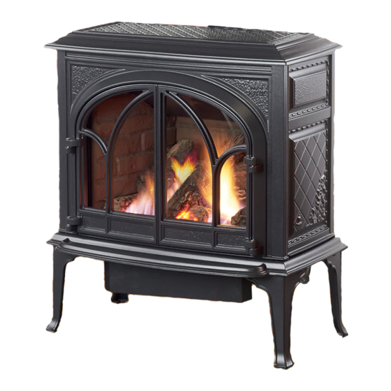
Jøtul GF 400 BV Sebago Installation And Operation Instructions Manual
Natural vent gas stove
Hide thumbs
Also See for GF 400 BV Sebago:
- Installation and operation instructions manual (28 pages) ,
- Installation and operation instructions manual (28 pages)
Table of Contents
Advertisement
WARNING: If the information in these
instructions is not followed exactly, a fire
or explosion may result causing property
damage, personal injury or loss of life.
– Do not store or use gasoline or other
flammable vapors and liquids in the vicinity
of this or any other appliance.
– WHAT TO DO IF YOU SMELL GAS
• Do not try to light any appliance.
• Do not touch any electrical switch; do not
use any phone in your building.
• Immediately call your gas supplier from a
neighbor's phone. Follow the gas supplier's
instructions.
• If you cannot reach your gas supplier, call
the fire department.
– Installation and service must be performed
by a qualified installer, service agency or the
gas supplier.
– In the Commonwealth of Massachusetts,
a carbon monoxide (CO) detector shall be
installed in the same room as the appliance.
This appliance may be installed in an aftermarket,
permanently located, manufactured home or mobile
home, where not prohibited by local codes.
This appliance is only for use with the types of gas
indicated on the rating plate. A conversion kit is
supplied with the appliance.
INSTALLER: Leave this manual with the appliance.
CONSUMER: Retain this manual for future reference.
Installation and
Operation Instructions
ATTENTION : CES INSTRUCTIONS DOIVENT
DEMUERER AVEC LE PROPRIÉTERE D'UNE
MAISON.
AVERTISSEMENT: Assurez-vous de bien
suivreles instructions données dans cette
notice pour réduire auninimum le risque
d'incendie ou d'explosion ou pour éviter
tout dommage matériel, toute blessure ou la
mort.
– Ne pas entreposer ni utiliser d'essence ni
d'autres vapeurs ou liquides inflammables
dans le voisinage de cet appareil ou de tout
autre appareil.
– QUE FAIRE SI VOUS SENTEZ UNE ODEUR DE GAZ:
• Ne pas tenter d'allumer l'appareil.
• Ne touchez à aucum interrupteur. Ne
pas vous servir des téléphones se trouvant
dans le bâtiment où vous trouvez.
• Appelez immédiatement votre
fournisseur de gaz depuis un voisin.
Suivez les instructions du fournisseur.
• Si vou ne pouvez rejoindre le
fournisseur de gaz, appelez le service des
incendies.
– L'installatione l'entretien doivent être
assurés par un installateur ou un service
d'entretien qualifié ou par le fournisseur
de gaz.
138301_Rev_G 10.4.11
1
Advertisement
Table of Contents

Subscribe to Our Youtube Channel
Related Manuals for Jøtul GF 400 BV Sebago


Summary of Contents for Jøtul GF 400 BV Sebago
-
Page 1: Operation Instructions
138301_Rev_G 10.4.11 Installation and Operation Instructions WARNING: If the information in these ATTENTION : CES INSTRUCTIONS DOIVENT instructions is not followed exactly, a fire DEMUERER AVEC LE PROPRIÉTERE D’UNE or explosion may result causing property MAISON. damage, personal injury or loss of life. AVERTISSEMENT: Assurez-vous de bien suivreles instructions données dans cette – Do not store or use gasoline or other notice pour réduire auninimum le risque flammable vapors and liquids in the vicinity d’incendie ou d’explosion ou pour éviter... -
Page 2: Service Tools
138301_Rev_G 10.4.11 WARNING Installation Requirements for the Commonwealth of Massachusetts THIS PRODUCT MUST BE INSTALLED BY HOT GLASS WILL A LICENSED MASTER OR JOURNEYMAN CAUSE BURNS PLUMBER OR GAS-FITTER WHEN INSTALLED IN THE COMMONWEALTH OF DO NOT TOUCH GLASS MASSACHUSETTS. UNTIL COOLED. 1. -
Page 3: Table Of Contents
138301_Rev_G 10.4.11 Jøtul GF 400 BV Table of Contents Sebago Service Tools ..........2 Gas Heater Specifications ..........4 General Information ........ 5 Manufactured and Distributed by: Safety Information ........6 Jøtul North America Installation Requirements Gorham, Maine U.S.A. Location ..........6 Hearth Protection .......6 Test Standards Clearances ..........7 This appliance complies with National Safety Mantel & Trim ........ -
Page 4: Specifications
138301_Rev_G 10.4.11 Jøtul GF 400 BV Sebago Specifications This appliance is an atmospherically-vented gas fireplace heater designed only for vertical venting directly to the outside of the house, using listed, Type B-vent pipe. Input Rates Natural Gas 40,000 BTU/hr. maximum input 22,000 BTU/hr. minimum input Propane 40,000 BTU/hr. maximum input 20,000 BTU/hr. minimum input Inlet Pressure:... -
Page 5: General Information
138301_Rev_G 10.4.11 General Information Consult the local or national installation code(s) to assure that adequate combustion and ventilation air is THIS HEATER MUST BE INSTALLED AND MAINTAINED available. BY A QUALIFIED SERVICE AGENCY. Installer l’appareil selon les codes ou reglements ... -
Page 6: Safety Information
138301_Rev_G 10.4.11 Safety Information Due to the high operating temperatures this appliance Cet appareil ne sert pas avec des portes en verre de should be located out of traffic and away from marché des accessoires. furniture, draperies, etc. Maintain proper clearance to Wear gloves and safety glasses while installing or combustible mantels and fireplace trim. performing maintenance procedures on this appliance. -
Page 7: Clearances
138301_Rev_G 10.4.11 Stove and Vent Clearance Requirements 3” Minimum Clearances from the Stove (51 mm) To Rear Wall to Combustibles See figs. 2-3. Rear: 3” (76 mm) - measured from Draft Hood Ceiling: 32 1/4” (819 mm) - measured from stove top 3” 3” Corner: 3” (76 mm) - measured from stove top (76 mm) (76 mm) Sides: 3” (76 mm - measured from stove top) Figure 2. Parallel Installation Clearances. Venting All sides: 1” (25 mm) 9 1/2”... - Page 8 138301_Rev_G 10.4.11 Vent Requirements The Jøtul GF 400 BV Sebago is specifically designed to Roof Pitch in Ft. operate using 4” Type B vent pipe components or a Listed Flexible gas liner. Flat to 6/12 ......1.0 Lowest Discharge Over 6/12 to 7/12 ..... 1.25 Opening • All venting components must be installed in Listed Over 7/12 to 8/12 ....1.5 Termination accordance with the terms of their listing and Over 8/12 to 9/12 .....
- Page 9 138301_Rev_G 10.4.11 Venting through a Masonry or Prefabricated Manufactured Chimney Listed termi- Storm collar • When 6” diameter decorative pipe is installed to nation cap required cover the venting any Listed Flexible Gas liner must Top sealing required achor plate be connected directly to the stove’s draft hood. • Use of single wall connector pipe as a vent is prohib- ited for use with the GF400 Sebago B-Vent stove.
-
Page 10: Vent Requirements
138301_Rev_G 10.4.11 Approved B-Vent Configurations Listed B-Vent Termi- Listed B-Vent nation Cap required. Termination Cap required. NOTE: Installation at Maximum Maximum altitude greater total horizontal chimney than 2000’ re- NOTE: anywhere height off quires minimum in venting Installation at Draft Hood is 12 ft. vertical rise configuration altitude greater... -
Page 11: Fuel Conversion
138301_Rev_G 10.4.11 Conversion Kit Contents: Fuel Conversion • 1, regulator tower labeled for propane • 3, regulator tower screws • 1, burner orifice (3.20 mm for NG, #49 for LPG) The Jøtul GF 400 BV gas stove is shipped from the factory • 1, pilot orifice (#51 for NG, #30 for LPG) equipped to burn NATURAL GAS only. If PROPANE gas is • Label A - to be completed and applied to to be used as fuel, the appliance must first be converted the back of the stove for use with propane. Use Propane Conversion Kit 156005, • Label B - apply to the stove’s Rating Plate... - Page 12 138301_Rev_G 10.4.11 Lift out the Burner Plate: NOTE: There are no screws securing the Burner to the floor of the firebox. Pull the Air Shutter forward and lift the burner together with shutter up and out of the stove as a unit. See fig. Air Shutter 8. Change the Burner Orifice. Using a ½” open ended wrench or deep-well socket, remove the burner orifice...
-
Page 13: Gas Supply Connection
138301_Rev_G 10.4.11 Apply small conversion label. Pilot Head Orifice Rubber Retainer Clip Gasket Regulator Valve Tower Pilot Base Figure 16. Pilot orifice removal and replacement. Figure 17. Regulator assembly. Gas Supply Connection 15. Install the new regulator: Be sure the new gasket is properly positioned and tighten screws securely. -
Page 14: Leak Test
138301_Rev_G 10.4.11 3/8” NPT x 3/8” Flare Fitting 1/2” x 3/8” Flare Shut-off Valve 3/8” Flex Tubing 3/8”Nipple Figure 19. Pressure test points. 3/8” Union Gas Stub 3/8” Close Nipple 3/8” Shut-off INLET GAS PRESSURES Valve 1/2” x 3/8” (inches water column) Reducer Figure 18. -
Page 15: Log Set Installation
138301_Rev_G 10.4.11 Log Set Installation Brick Kit Note: Install the optional Antique Brick Kit PN 220646 155370 before installing the logset. See page 22 and the instructions provided with that kit. The GF 400 BV logset must be installed before operating the burner. The logset includes five log pieces, and a bag of ember stones packaged inside the firebox. To install the log set, remove the packaging and place the parts inside the firebox as illustrated in figures 20-24. Do not handle the log set with your bare hands. -
Page 16: Flame Adjustment
138301_Rev_G 10.4.11 Flame Appearance / Air Shutter Optional Wall Thermostat or Adjustment Remote Control This stove is shipped from the factory equipped to burn Use only a 750 millivolt DC two-wire circuit thermostat Natural gas. If the stove has been converted for use with with this appliance. -
Page 17: Decorative Pipe
138301_Rev_G 10.4.11 System Check Installing Decorative Pipe 1. PURGING THE GAS LINE: When lighting the appliance The use of decorative pipe is optional. No decorative for the first time, it will take a few moments to clear pipe is included with the Jøtul GF 400 BV Sebago, the gas line of air. Once this purge is complete, the however, four locator brackets are included with the appliance will operate as described in the lighting stove in the hardware bag. -
Page 18: Operation
138301_Rev_G 10.4.11 If a vacuum is used during any service on the stove, WARNING: ALWAYS be sure the stove is cold and there are NO hot AIR SHUTTER ADJUSTMENTS SHOULD ONLY BE PER- embers. FORMED BY A QUALIFIED PROFESSIONAL SERVICE 5. Remember, this appliance has a continuous burning TECHNICIAN. pilot flame. Exercise caution when using products having combustible vapors. -
Page 19: Maintenance
138301_Rev_G 10.4.11 Maintenance REPLACE CRACKED OR BROKEN GLASS ONLY WITH JØTUL This stove and its venting system should be inspected CERAMIC GLASS REPLACEMENT KIT 155599. DO NOT before use and at least annually by a qualified service USE ANY OTHER TYPE OF GLASS WITH THIS APPLIANCE. technician. -
Page 20: Optional Blower
138301_Rev_G 10.4.11 Optional Blower # 156000 Connect the gas supply line to the stove, before installing the Blower. Use a 90° Elbow off the control valve to create clearance required for the blower installation. 1. Unpack and check the contents of the blower kit. Contact your dealer if any damage is evident or parts are missing. See fig. 33. 2. Attach the Snapstat Bracket to the studs located in the middle of the firebox floor using the two M6 hex nuts and a 10 mm wrench. See fig. 34. -
Page 21: Blower Operation
138301_Rev_G 10.4.11 Figure 35. Attach Blower to the Mounting Bracket with the wing screw and connect wires to Snapstat and female control quick-connect. Snapstat Connectors Male Quickconnector to Female Quick- connector Wing screw Blower Operation The optional variable-speed blower will enhance heat BLOWER circulation around the firebox and out into the room. The blower is controlled by a heat activated switch (snap- stat) that will ONLY function when the control switch is in AUTO setting. -
Page 22: Optional Antique Brick Kit
138301_Rev_G 10.4.11 Right Panel Left Panel 220601 220600 Optional Antique Brick Panel Kit #155375 Rear Panel 220599 Tools Required: Safety glasses and gloves Figure 47. Brick Kit Contents 1. Remove the Top Plate. Simply lift if up off of the stove body. It is not fastened. 2. -
Page 23: High Altitude Adjustment
138301_Rev_G 10.4.11 High Altitude Adjustment Figure 51. Locate Installations burning natural gas and located at altitudes and remove Air Shutter from 2000 - 4500 ft. (610 M - 1370 M), require compensa- the Air Shutter Wingnut OPEN tion for the thinner air (less volume of air per cubic foot). wingnut from CLOSED Higher altitudes affect the atmospheric pressure and heat under the right... -
Page 24: Illustrated Parts Breakdown
138301_Rev_G 10.4.11... -
Page 25: Replacement Parts List
138301_Rev_G 10.4.11 Jøtul GF 400 BV Sebago Parts List Brown Blue Matte Black Blue Black Ivory Jøtul Iron Jøtul Iron Majolica Majolica Paint Enamel Enamel Paint Enamel Cast Iron Parts Enamel Enamel 10. Left Side Plate 10391892 10421727 10421729 10391885 10421746 10421747 10421748 30. Bottom Plate... -
Page 26: Warranty Statement
138301_Rev_G 10.4.11 Jøtul Gas Product Limited Warranty 5) Damage caused by unauthorized modification, use or repair. This warranty policy applies to gas products identified by Jøtul, Scan, and Atra trade names, as set forth below. 6) Damage to enameled surfaces caused by improper operation or misuse, including use that is not in conformance with the A. Cast Iron, Steel Doors, Surround Components, Firebox: operating instructions contained in this owner’s manual. -
Page 27: Lighting Instructions
138301_Rev_G 10.4.11 LIGHTING INSTRUCTIONS FOR YOUR SAFETY, READ BEFORE LIGHTING. WARNING: IF YOU DO NOT FOLLOW THESE INSTRUCTIONS EXACTLY, A FIRE OR EXPLOSION MAY RESULT CAUS- ING PROPERTY DAMAGE, PERSONAL INJURY, OR LOSS OF LIFE. A. This appliance has a pilot which must be lit • If your gas supplier cannot be reached, call the fire department. by hand. When lighting the pilot, follow these instructions exactly. C. Use only your hand to push in or turn the gas control knob. - Page 28 138301_Rev_G 10.4.11 This appliance must be installed in conformance with local and national building regulations. Before beginning the installation, it is important that these instructions be carefully read and understood. Jøtul maintains a policy of continual product development. Consequently, products may differ in speci- fication, color or type of accessories from those illustrated or described in various publications.
Need help?
Do you have a question about the GF 400 BV Sebago and is the answer not in the manual?
Questions and answers