Table of Contents
Advertisement
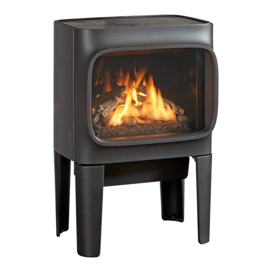
Jøtul GF 305 DV IPI
Direct Vent Gas Stove
Installation and
Operation Instructions
Conforms to ANSI Z21.88-2016 • CSA 2.33-2016,
CAN/CGA 2.17-M09, and CSA P.4-01.2-15
INSTALLER: Leave this manual with the appliance.
OWNER: Retain this manual for future reference.
WARNING: If the information in these
instructions is not followed exactly, a fire
or explosion may result causing property
damage, personal injury or loss of life.
– Do not store or use gasoline or other
flammable vapors and liquids in the
vicinity of this or any other appliance.
– WHAT TO DO IF YOU SMELL GAS
• Do not try to light any appliance.
• Do not touch any electrical switch; do
not use any phone in your building.
• Leave the building immediately.
• Immediately call your gas supplier
from a neighbor's phone. Follow the gas
supplier's instructions.
• If you cannot reach your gas supplier, call
the fire department.
– Installation and service must be performed
by a qualified installer, service agency or
the gas supplier.
– In the Commonwealth of Massachusetts,
a carbon monoxide (CO) detector shall
be installed in the same room as the
appliance.
This appliance may be installed in an aftermarket,
permanently located, manufactured home or
mobile home, where not prohibited by local codes.
This appliance is only for use with the types of gas
indicated on the rating plate. A conversion kit is
supplied with the appliance.
DANGER
!
A barrier designed to reduce the burn hazard
from the glass viewing area is provided with this
appliance and shall be installed for the protection
of children and other at-risk individuals.
139843_A GF 305 DV IPI 8/17
HOT GLASS WILL
CAUSE BURNS
.
DO NOT TOUCH GLASS
UNTIL COOLED.
NEVER ALLOW CHILDREN
TO TOUCH GLASS.
1
Advertisement
Table of Contents

Related Manuals for Jøtul GF 305 DV IPI


Summary of Contents for Jøtul GF 305 DV IPI
- Page 1 139843_A GF 305 DV IPI 8/17 WARNING: If the information in these instructions is not followed exactly, a fire or explosion may result causing property damage, personal injury or loss of life. – Do not store or use gasoline or other flammable vapors and liquids in the vicinity of this or any other appliance.
-
Page 2: Installation Requirements For The Commonwealth Of Massachusetts
139843_A GF 305 DV IPI 8/17 THIS OWNER’S MANUAL PROVIDES INFORMATION TO ENSURE Installation Requirements for the SAFE INSTALLATION AND EFFICIENT, DEPENDABLE OPERATION. PLEASE READ THESE INSTRUCTIONS IN THEIR ENTIRETY AND Commonwealth of Massachusetts MAKE THEM AVAILABLE TO ANYONE USING OR SERVICING THE APPLIANCE. -
Page 3: Table Of Contents
139843_A GF 305 DV IPI 8/17 Table of Contents Jøtul GF 305 DV IPI 1. Specifications ........4 Initial Assembly ......... 5 Direct Vent Gas Heater 3. General Information ......6 4. Safety Information ......6 Manufactured and Distributed by: Jøtul North America 5. -
Page 4: Specifications
12 1/2” Supply times. Should it become 318 mm Inlet damaged, contact your authorized Jøtul dealer 21 3/4” 15 1/8” 8” 6 1/4” for replacement. 552 mm 159 mm 384 mm 203 mm Figure 1.1 Dimensioned views, GF 305 DV IPI... -
Page 5: Initial Assembly
139843_A GF 305 DV IPI 8/17 2. Initial Assembly STOP! FOR EASIEST ACCESS, INSTALL CAUTION: Enamelled parts may be damaged ACCESSORIES, (Premium Kit, Accent Lamp, Flame if handled without care. The stove is heavy. Control, and/or Blower), BEFORE REMOVING THE Have assistance available to move it into position. -
Page 6: General Information
139843_A GF 305 DV IPI 8/17 3. General Information 4. Safety Information Due to the high operating temperatures this appliance THIS HEATER MUST BE INSTALLED AND MAINTAINED should be located out of traffic and away from BY A QUALIFIED SERVICE AGENCY. -
Page 7: Installation Requirements
139843_A GF 305 DV IPI 8/17 5. Installation Requirements Stove and Vent Clearance Location Requirements In selecting a location for the stove, consider the following points: Minimum Clearances from the Stove to Combustibles: 1) Heat distribution See figs. 5.2-4. 2) Vent termination requirements... - Page 8 139843_A GF 305 DV IPI 8/17 Alcove Installation Maximum Alcove Depth: 24” (607 mm) Minimum Alcove Width: 30” (826 mm) Minimum Alcove Ceiling Height from floor: 57 7/8” (1470 mm) Figure 5.3 Alcove Clearances. Clearance to Combustible Minimum Ceiling or Alcove Height Materials Above Stove Max.
-
Page 9: 6, Vent Requirements
139843_A GF 305 DV IPI 8/17 6. Venting Requirements The Jøtul GF 305 DV IPI gas stove may be installed with a RE-INSTALL THE TOP PLATE BEFORE vertical or horizontal termination and must conform to the configuration requirements described below. - Page 10 139843_A GF 305 DV IPI 8/17 MAXIMUM RESTRICTION RESTRICTION Figure 6.2. Use 1/4” socket driver to loosen the Exhaust Restrictor dial and adjust it to set the screw at the appropriate notch for your termination zone. 30 ft. (9.14m) TERMINATION APPROVED Min.
-
Page 11: Vertical Termination
139843_A GF 305 DV IPI 8/17 Vertical Vent Termination This appliance may be vertically vented through a ceiling or to a roof termination using the following guidelines: FUNCTIONALITY NOTE: LONG, VERTICAL VENT CONFIGURATIONS MAY The termination should fall within the shaded areas of ... - Page 12 INSTALLATION METHOD. THIS INSTALLATION IS NOT APPROVED IN CANADA. Use Standard M&G The GF 305 DV IPI is approved for use with masonry or DuraVent prefabricated chimney conversion kits made for this ProSeries Pipe specific purpose by other approved manufacturers.
-
Page 13: Horizontal Termination
139843_A GF 305 DV IPI 8/17 Horizontal Termination Any horizontal termination must fall within the shaded portion of the vent window matrix shown in fig. 6.3. Any horizontally terminated vent run must include a minimum vertical rise off the stove. See fig. 6.6. - Page 14 139843_A GF 305 DV IPI 8/17 Horizontal Termination Clearance Requirements 2 1/2” 12 ” 64 mm 3” 76 mm Figure 6.8. Vent Terminal Air Supply Terminals Prohibited in this Area Termination Clearance Figure 6.7. Vent Terminal Clearances, Canada and United States to overhangs.
-
Page 15: Fuel Conversion
Fuel Conversion Procedure 1. Turn off gas supply to stove. The GF 305 DV IPI gas stove is shipped from the factory equipped to burn NATURAL GAS only. If PROPANE gas is to 2. Open the door and use the Latch Tool provided to be used as fuel, the appliance must first be converted by remove the glass frame and open the firebox. - Page 16 139843_A GF 305 DV IPI 8/17 Figure 7.4. Reverse the Primary Air Air Shutter Shutter head to change orientation for the appropriate fuel. Injector Figure 7.3. Change the burner injector. 6. Change the Burner Injector. See fig. 7.3. Using a 1/2”...
-
Page 17: Gas Supply Connection
139843_A GF 305 DV IPI 8/17 8. Gas Supply Connection Route the gas supply line from the valve back to the left leg. Use the Left Utility Cover Plate included with the stove to hide the gas line between the plate and the leg. -
Page 18: Gas Pressure
Correct gas pressure is essential for efficient and The decreased atmospheric pressure of higher safe operation of the GF 305 DV IPI gas stove. It is altitudes affects heat value of gaseous fuels. Most important that the correct pressure is established gas suppliers derate the gas intended for use at at the time of the installation. -
Page 19: Optional Equipment
139843_A GF 305 DV IPI 8/17 11. Optional Equipment Optional Wall Thermostat 750003 PLEASE NOTE: To avoid interference between the two Fluted Panel Contents: Reflective Black Glass Contents: control devices, we advise against connecting a wall • Rear Panel ....226087 •... -
Page 20: Premium Upgrade Kits
139843_A GF 305 DV IPI 8/17 11. Premium Upgrade Kit #158030 - NG #158031 - LP Accent Lamp Kit 157469 Kit Contents: INSTALL THE LAMP BEFORE CONNECTING THE • Flame Control Kit (NG, 158032 / LP, 158033) STOVE TO VENTING. -
Page 21: Flame Control
139843_A GF 305 DV IPI 8/17 Wire Harness Lamp Box Lens Gasket Duct Deflector SHADE FLANGE Figure 11.4a. Accent Lamp assembly. ORIENT THE SHADE Figure 11.5. Accent Lamp Harness routing. FLANGE AS SHOWN. -
Page 22: Blower
139843_A GF 305 DV IPI 8/17 Blower Kit 158023 THIS BLOWER MUST BE ELECTRICALLY GROUNDED IN ACCORDANCE WITH LOCAL CODES OR, IN THE ABSENCE OF LOCAL CODES, WITH THE CURRENT ANSI/NFPA 70, NATIONAL ELECTRICAL CODE OR CSA C22.1- CANADIAN ELECTRICAL CODE. -
Page 23: Log Set Installation
139843_A GF 305 DV IPI 8/17 12. Log Set Installation NOTE: LOG COMPONENTS ARE FRAGILE. Back of Stove WEAR SAFETY GLOVES AND HANDLE LOGS WITH CARE. Before beginning assembly... Lay out all the components and take a few minutes to locate the identification numbers engraved into each part. - Page 24 139843_A GF 305 DV IPI 8/17 Square pocket on underside aligns with square knob on burner base. Figure 12.2. Beach Fire Rock and Stone identification. Figure 12.3. Beach Fire Log identification. Look for the ID numbers imprinted into the backside of each log.
- Page 25 139843_A GF 305 DV IPI 8/17 Log 3 Locator pins Log 4 Locator pins Log 6 Locator pins Log 5 Locator pins Step 2. Step 3. Engage Base Rocks 1 and 2 with the burner locator Engage the Lower Logs 3 and 4 with the adjacent pins shown in Step 1, page 23.
- Page 26 139843_A GF 305 DV IPI 8/17 Figure 12.4. Traditional Log Set identification. White outlined numbers show the relative position of ID number engraved on log. Traditional Log Set #158021 Lower Left Log 226228 #2 Lower Right Log 226229 Step 1.
- Page 27 139843_A GF 305 DV IPI 8/17 Log 5 Locator pins Log 6 Locator pins Step 3. • Engage the holes in Log 3 with the locators on Logs 1 and 2. • Engage the hole in Log 4 with the locator on Log 2.
-
Page 28: System Check
Once this purge is complete, the The GF 305 DV IPI gas stove is shipped from the factory appliance will operate as described in the lighting equipped to burn Natural gas and the air inlet shutter has instructions. - Page 29 139843_A GF 305 DV IPI 8/17 Front of Stove Air Shutter OPEN Wing Nut CLOSED Figure 14.1. Pull the shutter forward to increase primary air. Push it back to restrict air. Figure 14.2. Normal pilot flame picture. Figure 14.3. Normal burner flame picture.
-
Page 30: Operation Guidelines
139843_A GF 305 DV IPI 8/17 15. Operation Important Notes Check the build date on the shipping crate label. If it has been more than 6 months since the build date, be prepared to replace the backup batteries. 1. For the first several hours of operation, it is common... -
Page 31: Manual Operation
4. Set the Pilot Mode: • CPI for continuous pilot operation. • IPI for intermittent pilot operation. Gas Control Valve Control Switches Integrated Fireplace Contol Manual Regulator Function LED Battery Box Figure 15.1. GF 305 DV IPI Controls Compartment. - Page 32 139843_A GF 305 DV IPI 8/17 Proflame 2 Remote Control Features Overview The pilot assembly consists of a pilot hood, electrode, and The Proflame 2 Integrated Fireplace Control (IFC) a flame sensor. The electrode sends a spark to the pilot incorporates electronic remote control of the Jøtul GF...
-
Page 33: Remote Control
139843_A GF 305 DV IPI 8/17 Remote Control Functions Pilot Mode Initializing the System Set the stove switch to CPI mode for Proflame 2 1. Press the Controls Access Door to release its magnetic remote control. The IPI/CPI functionality will be catch and swing the panel down. - Page 34 139843_A GF 305 DV IPI 8/17 Remote Transmitter Controls Temperature Indication Display With the transmitter in the OFF position, press the Thermostat Key and the Mode Key at the same time. The display screen will show the current room temperature cycling between Fahrenheit and Celsius indicators each time the keys are pressed simultaneously.
- Page 35 139843_A GF 305 DV IPI 8/17 Room Thermostat (Transmitter Operation) The Remote Control can operate as a room thermostat. The thermostat can be set to a desired temperature to control the comfort level in a room. To activate this function, press the Thermostat Key. The ...
-
Page 36: Maintenance
139843_A GF 305 DV IPI 8/17 16. Maintenance Glass Care NOTICE: Clean the glass only when necessary. Wipe the surface THIS APPLIANCE AND VENT SYSTEM MUST BE with a clean, dampened, soft cloth. Follow with a dry, soft INSPECTED ANNUALLY BY A QUALIFIED GAS towel. -
Page 37: Battery Replacement - Transmitter
139843_A GF 305 DV IPI 8/17 Remote Transmitter Battery Replacement The life-span of transmitter batteries depends upon battery quality, the frequency of set point changes, freqency of ignition call changes, etc. When battery power is low, a Battery icon will appear on the transmitter display before all power is lost. -
Page 38: Appendix
139843_A GF 305 DV IPI 8/17 17. Appendix Figure 17.1 GF 305 DV IPI Proflame 2 Wiring Schematic including Premium Upgrade components... -
Page 39: Illustrated Parts Lists
139843_A GF 305 DV IPI 8/17 GF 305 DV IPI Illustrated Parts Breakdown Glass Assembly Fig. 17.6 Controls Compartment parts Figs. 17.3-4 No. Part No. Description 22593092 Rear Shroud 157712 Vent Adaptor - 6.625” dia. 129118 Gasket, Vent Adaptor - 6.625” dia. - Page 40 139843_A GF 305 DV IPI 8/17 Figure 17.3 GF 305 DV IPI Valve Assembly and IFC Components. No. Part No. Description No. Part No. Description 22593292 Control Compartment 117130 Hinge Bolt, Hex Hd Serr Flange, M6 x 12 mm 22993392...
- Page 41 139843_A GF 305 DV IPI 8/17 Figure 17.4 GF 305 DV IPI Pilot and Burner components. No. Part No. Description No. Part No. Description 226061 Exhaust Deflector, NG use only 222280 Gasket, Drop-in Orifice Holder 22545692 Lower Exhaust Baffle 223231...
- Page 42 22545492 Glass Frame 129124 Gasket, Tadpole - .25 dia. x 1.25”, 6 ft. Figure 17.5 GF 305 DV IPI Accent Lamp Assembly 225476 Glass Panel, Ceramic 157960 Replacement Glass Kit, GF 305 DV IPI Kit includes 220042 Replacement Glass Clips, 4 No.
-
Page 43: Utility Cover Plates
139843_A GF 305 DV IPI 8/17 Utility Cover Plate Installation This appliance incorporates Utility Cover Plates to help Use a 13 mm open end wrench to attach the plates to obscure the fuel line and power cord. These may be the legs using the M8 x 20 mm hex bolt supplied. -
Page 44: Mobile Home Requirements
139843_A GF 305 DV IPI 8/17 Mobile Home Installation THIS APPLIANCE MAY BE INSTALLED AS AN OEM The GF 305 DV IPI can be installed for use in a mobile INSTALLATION IN A MANUFACTURED (MOBILE) home in the U.S. and Canada with the following HOME AND MUST BE INSTALLED IN ACCORDANCE WITH THE MANUFACTURER’S INSTRUCTIONS AND... -
Page 45: Safety Screen Replacement
139843_A GF 305 DV IPI 8/17 Safety Screen Replacement DO NOT OPERATE THIS APPLIANCE WITH A DAMAGED OR MISSING SAFETY SCREEN. SERIOUS BURNS MAY RESULT FROM INADVERTENT CONTACT WITH THE GLASS PANEL EVEN WHEN THE APPLIANCE IS NOT OPERATING. REPLACE SCREEN WITH KIT NO. -
Page 46: Warranty Statement
139843_A GF 305 DV IPI 8/17 This warranty does not cover the following: 18. Jøtul Gas Product 1) Repair or replacement of parts that are subject to normal wear and tear during the warranty period or to parts that may require replacement Warranty in connection with normal maintenance. -
Page 47: Lighting Instructions
139843_A GF 305 DV IPI 8/17 LIGHTING INSTRUCTIONS FOR YOUR SAFETY, READ BEFORE LIGHTING. WARNING: IF YOU DO NOT FOLLOW THESE INSTRUCTIONS EXACTLY, A FIRE OR EXPLOSION MAY RESULT CAUSING PROPERTY DAMAGE, PERSONAL INJURY, OR LOSS OF LIFE. A. This appliance is equipped with an ignition device which automatically lights the pilot. - Page 48 Please record the serial number in the space below. You may also wish to attach your purchase receipt to this page for future reference. MODEL NAME: Jøtul GF 305 DV IPI SERIAL NUMBER:_______________________________ DATE OF PURCHASE:____________________________ AUTHORIZED DEALER:__________________________...
Need help?
Do you have a question about the GF 305 DV IPI and is the answer not in the manual?
Questions and answers