Jøtul GF 300 BV Allagash Installation And Operation Instructions Manual
Jotul gf300 bv allagash gas stove installation and operation instructions
Hide thumbs
Also See for GF 300 BV Allagash:
- Installation and operation instructions manual (28 pages) ,
- Installation and operation instructions manual (28 pages)
Table of Contents
Advertisement
Installation
and
Operation
Instructions
WARNING:
IF THE INFORMATION IN THESE INSTRUCTIONS
ARE NOT FOLLOWED EXACTLY, A FIRE OR EXPLO-
SION MAY RESULT CAUSING PROPERTY DAMAGE,
PERSONAL INJURY OR LOSS OF LIFE.
FOR YOUR SAFETY:
DO NOT STORE OR USE GASOLINE OR OTHER
FLAMMABLE VAPORS AND LIQUIDS IN THE VICIN-
ITY OF THIS OR ANY OTHER APPLIANCE.
INSTALLATION:
INSTALLATION AND SERVICE MUST BE PER-
FORMED BY A QUALIFIED INSTALLER, SERVICE
AGENCY OR LICENSED GAS SUPPLIER.
THIS PRODUCT MUST BE INSTALLED BY A
LICENSED PLUMBER OR GAS-FITTER WHEN
INSTALLED IN THE COMMONWEALTH OF
MASSACHUSETTS.
A CARBON MONOXIDE (CO) DETECTOR SHALL
BE INSTALLED IN THE SAME ROOM AS THE
APPLIANCE.
WHAT TO DO IF YOU SMELL GAS:
• DO NOT TRY TO LIGHT ANY APPLIANCE.
• DO NOT TOUCH ANY ELECTRICAL SWITCHES.
• DO NOT USE THE PHONE IN YOUR BUILDING.
IMMEDIATELY CALL YOUR GAS SUPPLIER FROM A
NEIGHBOR'S PHONE.
• FOLLOW YOUR GAS SUPPLIER'S INSTRUCTIONS.
• IF YOU CANNOT REACH YOUR GAS SUPPLIER,
CALL THE FIRE DEPARTMENT.
AVERTISSEMENT:
ASSUREZ-VOUS DE BIEN SUIVRE LES INSTRUC-
TIONS DANS CETTE NOTICE POUR REDUIRE AU
MINIMUM LE RISQUE D'INCENDIE OU POUR EVITER
TOUT DOMMAGE MATERIEL, TOUTE BLESSURE OU
MORTALIT'E.
NE PAS ENTREPOSER NI UTILISER D'ESSENCE NI
OU LIQUIDES INFLAMMABLES DANS LE VOISINAGE
DE CET APPAREIL OU DE TOUT AUTRE APPAREIL.
L'INSTALLATION LE SERVICE DOIVENT ETRE
EXECUTES PAR UN INSTALLATEUR QUALIFIE,
AGENCE DE SERVICE OU LE FOURNISSEUR DE
GAZ.
QUE FAIRE SI VOUS SENTEZ UNE ODEUR DE GAZ.
• NE PAS TENTER D'ALLUMER L'APPAREIL
• NE TOUCHEZ A AUCUM NTERRUPTEUR.
• NE PAS VOUS SERVIR DES TELEPHONES SE
TROUVANT DANS LE BATIMENT OU VOUS VOUS
TROUVEZ.
• APPELEZ IMMEDIATEMENT VOTRE FOURNISSEUR
DE GAZ CHEZ UN VOISIN. SUIVEZ LES INSTRUC-
TIONS DU FOURNISSEUR.
• SI VOUS NE POUVEZ REJOINDRE LE
FOURNISSEUR DE GAZ, APPELEZ LE SERVICE DES
INCENDIES.
1
Advertisement
Table of Contents

Related Manuals for Jøtul GF 300 BV Allagash


Summary of Contents for Jøtul GF 300 BV Allagash
- Page 1 Installation Operation Instructions WARNING: IF THE INFORMATION IN THESE INSTRUCTIONS ARE NOT FOLLOWED EXACTLY, A FIRE OR EXPLO- SION MAY RESULT CAUSING PROPERTY DAMAGE, PERSONAL INJURY OR LOSS OF LIFE. FOR YOUR SAFETY: DO NOT STORE OR USE GASOLINE OR OTHER FLAMMABLE VAPORS AND LIQUIDS IN THE VICIN- ITY OF THIS OR ANY OTHER APPLIANCE.
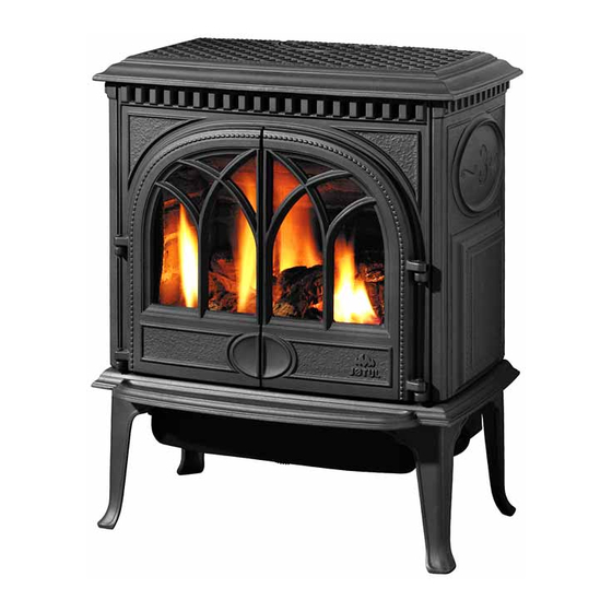
- Page 2 1853. The Jøtul GF 300 BV Allagash combines advanced gas technology with the warm, traditional elements of cast iron. With proper care and use, your stove will provide you with many years of safe, dependable and satisfying service. Please take a few minutes to familiarize yourself with this manual and the features of your new Jøtul...
-
Page 3: Table Of Contents
Table of Contents Service Tools ... 4 Specifications ... 4 General Information ... 5 Safety Information ... 6 Installation Requirements Location ... 6 Hearth Protection ... 6 Clearances ... 7 Mantel & Trim ... 7 Alcove ... 7 Vent Requirements ... 10 Fuel Conversion ... -
Page 4: Dimensions
GF 300 BV Allagash Specifications The Jøtul GF300 BV Allagash is a atmospherically- vented gas fireplace heater designed only for vertical venting directly to the outside of the house, using listed, Type B-vent pipe. Input Rates Natural Gas 26,000 BTU/hr. maximum input 15,000 BTU/hr. -
Page 5: General Information
Only remove glass for routine service. Always handle glass carefully. Unpacking your stove 1. Remove the Top Plate of the stove by simply lifting it straight off of the stove body. 2. To open the firebox, disengage the two Glass Frame Latches located on top of the firebox. -
Page 6: Safety Information
Also, “fire-rated” sheet rock is considered combustible. Hearth Requirements The GF 300 BV gas stove CANNOT be installed directly on carpeting, vinyl, linoleum or Pergo If this appliance will be installed on any combustible material OTHER THAN WOOD, a floor pad must be installed that is either metal or wood, or a listed hearth pad. -
Page 7: Stove And Vent Clearance Requirements
24” (610 mm) Height: 61” (1550 mm) Mantel Clearances - Stove shown with standard legs. With Short Legs, subtract 2 1/4” (51 mm) from the clearances indicated below. Figure 4. Mantel and Trim specifications - Stove installed flush with fireplace face. -
Page 8: Vent Requirements
• When venting through a thimble into a masonry flue, any venting exposed in the room must be Type B venting, or a flexible liner sleeve within 24 ga. 6” stove pipe. • Listed Flexible Gas Liners may not be exposed in any living space. - Page 9 • When 6” diameter decorative pipe is installed to cover the venting any Listed Flexible Gas liner must be connected directly to the stove’s draft hood. • Use of single wall connector pipe as a vent is prohibited for use with the GF300 Allagash B-Vent stove.
- Page 10 Approved B-Vent Configurations Listed B-Vent Termination Cap required. NOTE: Installation at altitude greater than 2000’ requires minimum 12 ft. vertical rise from Draft Hood. Figure 7. Listed B-Vent termination cap required. NOTE: Installation at altitude greater than 2000’ requires chimney height minimum 12 ft.
-
Page 11: Fuel Conversion
Fuel Conversion The GF 300 BV gas stove is shipped from the factory equipped to burn NATURAL GAS only. If PROPANE gas is to be used as fuel, the appliance must first be converted for use with propane. Use Propane Conversion Kit 155592, supplied with the appliance. - Page 12 Burner to the floor of the firebox. Pull the Air Shutter forward and lift the burner together with shutter up and out of the stove as a unit. See fig. 13. 8. Change the Burner Orifice. See fig. 14. Using a ½”...
-
Page 13: Gas Connection
15. Install the new regulator: Be sure the new gasket is properly positioned and tighten screws securely. 16. Install the identification labels to the stove so that they can be seen by any person that may be servicing the stove. -
Page 14: Gas Pressure
Gas Pressure Correct gas pressure is essential for efficient and safe operation of the GF 300 BV gas stove. It is important that the correct pressure is established at the time of the installation. Proper gas pressure provides a consistent flow of gas to the appliance and is instru- mental in checking for gas leaks. -
Page 15: Log Set Installation
NOTE: You do not need to use all of the ember stones. With experimentation, you will find the arrangement and quantity of embers that works best with your stove. Depending upon the characteristics of your installation, it is possible that too many ember stones can pro- mote sooting on the logs. -
Page 16: Flame Appearance/Air Shutter Adjustment
To adjust the air shutter: 1. Reach under the right side of the stove and loosen the wingnut located closest to you. See fig. 25. Slide the wingnut stud forward to open the air shutter and back to provide less air. -
Page 17: Decorative Pipe
2. Align the “L”- shaped pipe brackets with the holes on the Flue Collar and attach using the four 1/4” hex head screws, located in the Misc. Hardware Bag. Reminder: Do not use single wall stove pipe as the vent pipe on this appliance. Spill Switch Figure 27. -
Page 18: Operation
If a vacuum is used during any service on the stove, ALWAYS be sure the stove is cold and there are NO hot embers. 5. Remember, this appliance has a continuous burning pilot flame. -
Page 19: Maintenance
3. Lift the glass frame all the way up and out of the top of the stove. Lay this assembly on a flat surface, protecting the frame from scratches using a blanket or towel. -
Page 20: Optional Blower
M6 hex nuts and a 10 mm wrench. See fig. 34. 3. Attach the Blower to the stove with the screen opening to the rear using the two M6 flange head hex bolts as shown in fig. 35. -
Page 21: Blower Operation
Figure 35. Attach Blower to the stove bottom and connect wires to Snapstat and female control quick connect. Blower Operation The optional variable-speed blower will enhance heat circulation around the firebox and out into the room. The blower is controlled by a heat activated switch (snapstat) that will ONLY function when the control switch is in AUTO setting. -
Page 22: Optional Antique Brick Kit
2. Remove the Glass Frame. Disengage the two com- pression latches located at the top of the firebox and lift the glass frame up and off of the stove. See fig. 39. 3. If installed, remove the Logset. These parts are not fastened. -
Page 23: High Altitude Adjustment
High Altitude Adjustment Installations burning natural gas and located at altitudes from 2000 - 4500 ft. (610 M - 1370 M), require compen- sation for the thinner air (less volume of air per cubic foot). Higher altitudes affect the atmospheric pressure and heat value of gaseous fuels. -
Page 25: Replacement Parts List
GF 300 BV Allagash Parts List Cast Iron Parts Matte Black Side Plate 10203292 Base Plate 10390092 Legs, (4) 10192592 Front Panel 10390192 Right Door 10390492 Top Plate 10390292 Left Door 10390392 Side Clip ... 128401 Bolt, M6 x 12 mm (Side to Base) ... 117130 Bolt, M6 x 25 mm (Side to Front) ... - Page 26 MODEL NAME: ________________________ SERIAL NUMBER: ______________________ DATE OF PURCHASE: ___________________ PURCHASED FROM: ____________________ NAME OF INSTALLER: ___________________ TYPE OF FUEL: ________________________ WAS STOVE CONVERTED? _______________ NOTES: RETAIN THIS MANUAL FOR REFERENCE AND MAKE IT AVAILABLE TO ANYONE USING OR SERVICING THE STOVE.
-
Page 27: To Turn Off Gas
1. STOP! Read the safety information above. 2. Access the lower controls. 3. Turn the stove ON/OFF switch to “OFF”, or set the thermostat to lowest setting (if used). 4. Confirm that the gas supply line shut-off valve is open. - Page 28 This appliance must be installed in conformance with local and national building regulations. Before beginning the installation, it is important that the these instructions be carefully read and understood. Jøtul maintains a policy of continual product development. Consequently, products may differ in specification, color or type of accessories from those illustrated or described in various publications.
Need help?
Do you have a question about the GF 300 BV Allagash and is the answer not in the manual?
Questions and answers