Jøtul GF 370 DV II Installation And Operation Instructions Manual
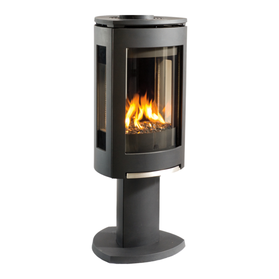
Direct vent gas stove
Hide thumbs
Also See for GF 370 DV II:
- Installation and operation instructions manual (40 pages) ,
- Fuel conversion instructions (4 pages) ,
- Adjustment instructions (2 pages)
Table of Contents
Advertisement
Jøtul GF 370 DV II
Direct Vent Gas Stove
Installation and
Operation Instructions
INSTALLER: Leave this manual with the appliance.
CONSUMER: Retain this manual for future reference.
WARNING: If the information in these
instructions is not followed exactly, a fire or
explosion may result causing property damage,
personal injury or loss of life.
– Do not store or use gasoline or other
flammable vapors and liquids in the
vicinity of this or any other appliance.
– WHAT TO DO IF YOU SMELL GAS
• Do not try to light any appliance.
• Do not touch any electrical switch; do
not use any phone in your building.
• Immediately call your gas supplier
from a neighbor's phone. Follow the gas
supplier's instructions.
• If you cannot reach your gas supplier, call
the fire department.
– Installation and service must be performed
by a qualified installer, service agency or
the gas supplier.
– In the Commonwealth of Massachusetts,
a carbon monoxide (CO) detector shall
be installed in the same room as the
appliance.
This appliance may be installed in an aftermarket,
permanently located, manufactured home or
mobile home, where not prohibited by local codes.
This appliance is only for use with the types of gas
indicated on the rating plate. A conversion kit is
supplied with the appliance.
Advertisement
Table of Contents

Related Manuals for Jøtul GF 370 DV II


Summary of Contents for Jøtul GF 370 DV II
- Page 1 – Installation and service must be performed by a qualified installer, service agency or the gas supplier. Jøtul GF 370 DV II – In the Commonwealth of Massachusetts, Direct Vent Gas Stove a carbon monoxide (CO) detector shall be installed in the same room as the appliance.
-
Page 2: Installation Requirements For The Commonwealth Of Massachusetts
139467_03 GF 370 DV II June 2015 THIS OWNER’S MANUAL PROVIDES INFORMATION TO Installation Requirements for the ENSURE SAFE INSTALLATION AND EFFICIENT, DEPENDABLE Commonwealth of Massachusetts OPERATION OF YOUR FIREPLACE INSERT. PLEASE READ THESE INSTRUCTIONS IN THEIR ENTIRETY AND MAKE THEM... -
Page 3: Table Of Contents
General Information ........5 2. Confirm stove contents. Safety Information ........6 The Jøtul GF 370 DV II includes the following loose Installation items shipped in the Miscellaneous Hardware bag; Hearth Requirements ......7 • 4 mm hex key - used to remove the Clearances ..........7... -
Page 4: Specifications
139467_03 GF 370 DV II June 2015 Jøtul GF 370 DV II Accessories Direct Vent Gas Stove Traditional Log Set ..........#156789 River Rocks Set ............#157428 Manufactured and Distributed by: Jøtul North America Tumbled Stones ............ #157243 Gorham, Maine USA StarFire Glass Embers, Black ....... -
Page 5: General Information
139467_03 GF 370 DV II June 2015 General Information THIS HEATER MUST BE INSTALLED AND 5. Do not operate this fireplace if any part of it has MAINTAINED BY A QUALIFIED SERVICE AGENCY. been under water.. DO NOT ATTEMPT TO ALTER OR MODIFY... -
Page 6: Safety Information
139467_03 GF 370 DV II June 2015 Safety Information Due to the high operating temperatures this WARNING! appliance should be located out of traffic and away from furniture and draperies. Maintain Shock Hazard. Can cause severe injury or death. -
Page 7: Installation
7” Hearth Requirements Figure 4. Alcove and Wall Clearances. ALCOVE SPECIFICATIONS: The Jøtul GF 370 DV II has been approved for installation directly on combustible floor materials, Maximum Alcove Depth: 21 3/4” (55.2 cm) including carpeting. No additional floor protection is Minimum Alcove Width: 31 1/4”... -
Page 8: Approved Vent Manufacturers
INSTALLATION. Approved Vent Manufacturers Vertical Venting and Termination The Jøtul GF 370 DV II stove is approved for installa- The Jøtul GF 370 DV II can be vertically vented tion with direct vent chimney components supplied through a roof or ceiling. Follow these guidelines... -
Page 9: Masonry Chimney Conversion
Figure 8. Vent System through a masonry chimney using the Simpson Dura-Vent Chimney Conversion Kit The GF 370 DV II is approved for use with direct vent chimney conversion kits in a masonry chimney or 46DV IIA-KMC and 46DV IIA-KCT components. Other a prefabricated solid fuel listed chimney. -
Page 10: Horizontal Termination
139467_03 GF 370 DV II June 2015 Horizontal Termination Figure 9. Minimum vent pipe sections required for Minimum vertical rise from the vent collar is a 24” horizontal termination: section vent pipe. See fig. 9. Minimum horizontal A = 12” with NG run is 12”... - Page 11 139467_03 GF 370 DV II June 2015 Horizontal Termination Clearance 2 1/2” 12 ” 64 mm 3” 76 mm Figure 13. Termination Clearance to overhangs. Vent Terminal Air Supply Terminals Prohibited in this Area Figure 12. Vent Terminal Clearances - ANSI Z21.88-2014, CSA 2.33-2014, and National Fuel Gas Code.
-
Page 12: Vent Restriction Adjustments
139467_03 GF 370 DV II June 2015 Vent Restriction Adjustments The Jøtul GF 370 DV II features adjustment controls for Exhaust Restrictor Adjustment both intake air and exhaust to accommodate a variety 1. Remove the Trim Rings from the Top Plate. -
Page 13: Vent Termination Diagram
139467_03 GF 370 DV II June 2015 A maximum of 35 Ft. two 90° or four 45° (10.67 m) elbows may be used. ZONE Whenever possible, use 45° elbows instead of 90° elbows as these offer less restriction to 30 Ft. -
Page 14: Stove Assembly
139467_03 GF 370 DV II June 2015 Stove Assembly 1. Glass Frame Removal To access the firebox, use the 4 mm hex key to remove the four socket head screws that attach the glass frame to the firebox. See fig. 18. -
Page 15: Gas Pressure
139467_03 GF 370 DV II June 2015 3/8” NPT x 3/8” Flare Fitting Inlet Pressure 1/2” x 3/8” Flare Shut-off Valve Natural Gas: 5.0 WC (1.24 kPa) 7.0 WC (1.74 kPa) Propane: 12.0 WC (2.99 kPa) 14.0 WC (3.48 kPa) 3/8”... -
Page 16: Fuel Conversion
• Label B - apply to the rating plate in the space indi- cated on the plate. • Small valve label - apply to valve body The GF 370 DV II gas stove is shipped from the factory • Conversion instructions equipped to burn Natural gas. Propane fuel conver-... - Page 17 139467_03 GF 370 DV II June 2015 Pilot Hood Ignitor Flame Sensor Primary Air Shutter Orifice Lever Injector Regulator Diaphragm IFC Reset Button Regulator Use new Torx Tower screws supplied Figure 23. Fuel conversion components and assemblies 8. Reinstall the Burner Plate by engaging the 12 .
-
Page 18: High Altitude Adjustment
139467_03 GF 370 DV II June 2015 7. Firebox Panel Installation 6. High Altitude Adjustment Skamol Panels and optional The decreased atmospheric pressure of higher alti- Reflective Glass Kit 156817 tudes affects heat value of gaseous fuels. Most gas suppliers derate the gas intended for use at eleva- Skamol Panels tions above 2000 feet. - Page 19 139467_03 GF 370 DV II June 2015 8. Install Burner Media River Rocks CAUTION: THE ROCKS ARE FRAGILE! SUPPORT THE ASSEMBLY FROM THE BOTTOM AND HANDLE CARE- FULLY! 1. Engage the River Rock bed with the two center burner pins as shown in fig. 27. Either side of the rocks may face outward as desired.
- Page 20 139467_03 GF 370 DV II June 2015 Tumbled Stones Install the stones according to the instructions sup- plied with that kit. Install the Log Set The three-piece log set includes a bag of ember stones that simulate glowing coals when the burner is operating.
-
Page 21: System Check
139467_03 GF 370 DV II June 2015 10. Initial System Check 3. Set the Pilot Mode: • CPI for continuous pilot operation or Proflame 2 Remote functionality. The burner and fan control system consists of the • IPI for intermittent operation. - Page 22 139467_03 GF 370 DV II June 2015 Flame Appearance / Air Shutter Adjustment WARNING: AIR SHUTTER ADJUSTMENTS SHOULD ONLY BE PERFORMED BY A QUALIFIED, PROFESSIONAL SERVICE TECHNICIAN. Locate the Primary Air Shutter control under the firebox floor above the gas valve. See fig. 37. The shutter is set at the midpoint of its adjustment range at the factory.
-
Page 23: Operation
139467_03 GF 370 DV II June 2015 Proflame 2 Pilot Assembly Remote Control The pilot contains a pilot hood, igniter, and a flame sensor. The igniter sends a spark to the pilot hood which lights the gas. The sensor is then engulfed by the pilot Features Overview flame, flame rectification occurs and the unit remains lit. -
Page 24: Control Functions
139467_03 GF 370 DV II June 2015 Control Functions Initializing the System 1. Press the Controls Access Door to release the magnetic Pilot Mode catch and swing the panel down. Switch the Burner to OFF. Set the stove switch to CPI mode for Proflame 2 remote control. - Page 25 139467_03 GF 370 DV II June 2015 Remote Transmitter Controls, cont’d. Temperature Indication Display W ith the transmitter in the OFF position, press the Thermostat Key and the Mode Key at the same time. The display screen will show the current room temperature cycling between Farenheit and Celsius Figure 42.
- Page 26 139467_03 GF 370 DV II June 2015 SMART Thermostat Function This function adjusts the flame intensity according to the difference in the Set Point temperature and the actual room temperature. As the room temperature gets closer to the Set Point, the Smart Function will modulate flame intensity down.
-
Page 27: Wiring Diagrams
FONCTIONNEMENT INADÉQUAT ET DANGEREUX. Optional SIT Proflame 2 IFC Variable Lamp 120VAC Power Optional Variable Speed Blower Figure 58. GF 370 DV II with Proflame 2 Premium Remote Control Accessories Figure 59. Wiring Diagram - GF 370 DV II Fan... - Page 28 139467_03 GF 370 DV II June 2015 This page is intentionally blank.
-
Page 29: Maintenance
139467_03 GF 370 DV II June 2015 Maintenance This appliance and its venting system should be NOTE: INSPECT THE GLASS SURFACE FOR SCRATCHES inspected before use and at least annually by a AS THESE CAN WEAKEN THE PANEL TENSILE qualified service technician. -
Page 30: Battery Replacement
139467_03 GF 370 DV II June 2015 Initializing the Remote Control Figure 61. 156835 Each time you replace the batteries, you will need to Front Glass initialize communication between the Receiver and Replacement the Transmitter. Kit includes 1. Place the slider switch in the REMOTE position. - Page 31 139467_03 GF 370 DV II June 2015 Figure 63. Firebox Part Identification. No. Part Number Description No. Part Number Description 9911 Bolt, Hex Cap, M6x45, DIN 933, Class 8.8, Blk 22298392 Simpson DV II Starter Collar, GF 370, MB 9962 Bolt, Hex Cap M6x10 DIN 933 8.8 Ser Flange Blk...
- Page 32 139467_03 GF 370 DV II June 2015 Figure 64. GF 37 DVII Spud assembly parts identification - For stoves with serial numbers after 10000.
- Page 33 139467_03 GF 370 DV II June 2015 Use only genuine Jøtul Replacement Parts available from your local Authorized Jøtul Dealer or by contacting: Part Number Description Jøtul North America 55 Hutcherson Dr. 118066 Screw, #12 X 2”, HWH Type A, STL zinc...
- Page 34 139467_03 GF 370 DV II June 2015 Figure 65. External parts identification No. Part Number Description Part Number Description 9962 Bolt, Hex Cap M6x10 DIN 933 8.8 Ser Flange Blk 156843 Lower Door Hinge Asy. GF 370, MB 99115 Bolt, Hex Head M8 x 12 Blk...
-
Page 35: Mobile Home Installation
Appendix A Mobile Home Installation Correct Flame Pictures The Jøtul GF 370 DV II can be installed for use in a mobile home in the U.S. and Canada provided: 1. The stove must be secured to the floor of the mobile home. - Page 36 139467_03 GF 370 DV II June 2015 Jøtul GF 370 DV II Limited Lifetime Warranty Effective January 1, 2013 This warranty policy applies to gas products identified component is covered by this warranty, the repair or replacement will be made as set forth above. This warranty is not transferable by Jøtul, Scan, and Atra trade names, as set forth below.
- Page 37 MODEL NAME: Jøtul GF 370 DV II Gas Stove JØTUL reserves the right to discontinue, modify or change the materials used to produce the Jøtul, Scan, or Atra Gas Stove or SERIAL NUMBER:_______________________________ Fireplace.
- Page 38 139467_03 GF 370 DV II June 2015 Figure 66. Remove top plate. Remove temporary spacers and replace top plate.
-
Page 39: Lighting Instructions
139467_03 GF 370 DV II June 2015 LIGHTING INSTRUCTIONS FOR YOUR SAFETY, READ BEFORE LIGHTING. WARNING: IF YOU DO NOT FOLLOW THESE INSTRUCTIONS EXACTLY, A FIRE OR EXPLOSION MAY RESULT CAUSING PROPERTY DAMAGE, PERSONAL INJURY, OR LOSS OF LIFE. A. This appliance is equipped with an ignition •... - Page 40 139467_03 GF 370 DV II June 2015 This appliance must be installed in conformance with local and national building regulations. Before beginning the installation, it is important that the these instructions be carefully read and understood. Jøtul maintains a policy of continual product development. Consequently, products may differ in specification, color or type of accessories from those illustrated or described in various publications.
Need help?
Do you have a question about the GF 370 DV II and is the answer not in the manual?
Questions and answers