Table of Contents
Advertisement
Quick Links
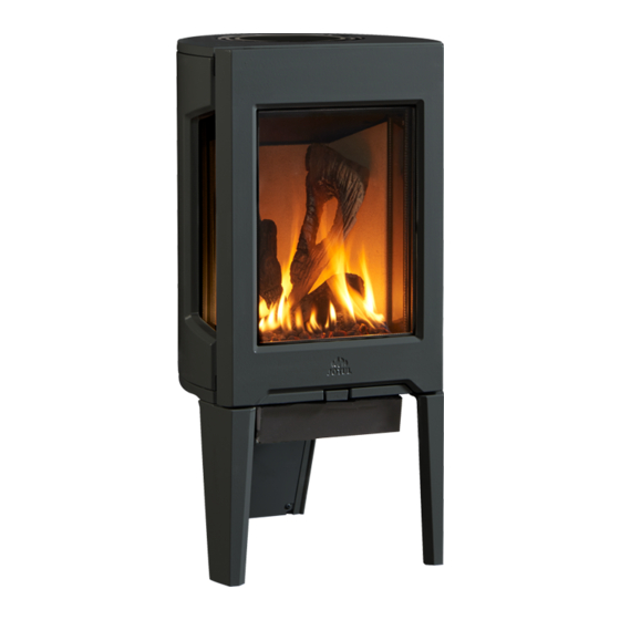
Jøtul GF 160 DV
Direct Vent Gas Stove
Continuous Pilot Ignition
Installation and
Operation Instructions
Certified to ANSI Z21.88-2019 • CSA 2.33-2019
and CAN/CGA 2.17-M17.
INSTALLER: Leave this manual with the appliance.
OWNER: Retain this manual for future reference.
WARNING: If the information in these
instructions is not followed exactly, a fire or
explosion may result causing property damage,
personal injury or loss of life.
– Do not store or use gasoline or other flammable
vapors and liquids in the vicinity of this or any
other appliance.
– WHAT TO DO IF YOU SMELL GAS
• Do not try to light any appliance.
• Do not touch any electrical switch; do not
use any phone in your building.
• Leave the building immediately.
• Immediately call your gas supplier from a
neighbor's phone. Follow the gas supplier's
instructions.
• If you cannot reach your gas supplier, call the
fire department.
– Installation and service must be performed by
a qualified installer, service agency or the gas
supplier.
– In the Commonwealth of Massachusetts,
a carbon monoxide (CO) detector shall be
installed in the same room as the appliance.
This appliance may be installed in an aftermarket,
permanently located, manufactured home or mobile
home, where not prohibited by local codes.
This appliance is only for use with the types of gas
indicated on the rating plate. A conversion kit is supplied
with the appliance.
DANGER
!
!
A barrier designed to reduce the burn hazard
from the hot viewing glass is provided with this
appliance and must be installed for the protection
of children and other at-risk individuals.
130112_Rev 2 GF 160 DV 2/22
HOT GLASS WILL
CAUSE BURNS.
DO NOT TOUCH GLASS
UNTIL COOLED.
NEVER ALLOW CHILDREN
TO TOUCH GLASS.
1
Advertisement
Table of Contents

Related Manuals for Jøtul GF 160 DV


Summary of Contents for Jøtul GF 160 DV
- Page 1 130112_Rev 2 GF 160 DV 2/22 WARNING: If the information in these instructions is not followed exactly, a fire or explosion may result causing property damage, personal injury or loss of life. – Do not store or use gasoline or other flammable vapors and liquids in the vicinity of this or any other appliance.
- Page 2 130112_Rev 2 GF 160 DV 1/22 THIS OWNER’S MANUAL PROVIDES INFORMATION Installation Requirements for the TO ENSURE SAFE INSTALLATION AND EFFICIENT, DEPENDABLE OPERATION. PLEASE READ THESE Commonwealth of Massachusetts INSTRUCTIONS IN THEIR ENTIRETY AND MAKE THEM THIS PRODUCT MUST BE INSTALLED BY...
-
Page 3: Table Of Contents
130112_Rev 2 GF 160 DV 2/22 Table of Contents Jøtul GF 160 DV 1. Specifications ........4 Initial Assembly ........5 Direct Vent Gas Heater 3. General Information ......6 Manufactured and Distributed by: Jøtul North America 4. Safety Information ......6 55 Hutcherson Dr. -
Page 4: Specifications
• Rock Wool Embers, 1 oz........157259 24,000 BTU/hr. maximum input • Door Adjustment Washers, 3 ......117587 Propane • GF 160 DV Manual ..........130112 19,800 BTU/hr. minimum input • Top Plate Grill, 2 : Matte Black ....22299592 24,000 BTU/hr. maximum input... -
Page 5: Initial Assembly
130112_Rev 2 GF 160 DV 2/22 2. Initial Assembly STOP! FOR EASIEST ACCESS, CAUTION: Enamel parts may be damaged if handled without care. The stove is heavy. INSTALL FUEL CONVERSION NOT DRAG THE STOVE LEGS. AND FIREBOX PANELS BEFORE Have assistance available to move the stove into position. -
Page 6: General Information
130112_Rev 2 GF 160 DV 1/22 3. General Information 4. Safety Information Due to the high operating temperatures this appliance should be located out of traffic and away from furniture and draperies. THIS HEATER MUST BE INSTALLED AND Maintain proper clearance to combustible mantels and fireplace trim. -
Page 7: Installation Requirements
130112_Rev 2 GF 160 DV 2/22 5. Installation Requirements Stove and Vent Clearance Location Requirement In selecting a location for the stove, consider the following points: Minimum Clearances from the Stove to Combustibles: 1) Heat distribution Measured from: 2) Vent termination requirements Rear: 2”... - Page 8 130112_Rev 2 GF 160 DV 1/22 Alcove Installation Maximum Alcove Depth: 24” Minimum Alcove Width*: 32 1/2” Minimum Alcove Ceiling Height from floor: 69” * Alcove clearances are determined through testing in specific construction configurations which often result in greater clearances than an open stove installation.
-
Page 9: 6, Vent Requirements
130112_Rev 2 GF 160 DV 2/22 6. Venting Requirements The Jøtul GF 160 DV gas stove may be installed with a vertical or horizontal termination and must conform to the configuration requirements described below. Figure 6.1. DO NOT USE SILICONE This appliance is approved for use with vent systems from SEALANT. - Page 10 130112_Rev 2 GF 160 DV 1/22 35 ft. Approved Horizontal and Vertical Vent (10.67 m) Terminations • ALL VENTING MUST TERMINATE (END) WITHIN ONE OF THE DESIGNATED AREAS. • SET STOVE EXHAUST RESTRICTOR TO THE POSITION THAT CORRESPONDS TO THE VENT TERMINATION AREA IN THE MATRIX.
-
Page 11: Vertical Termination
130112_Rev 2 GF 160 DV 2/22 Vertical Vent Termination Note: Co-linear installations of any This appliance may be vertically vented through a ceiling or to a height are set at roof termination using the following guidelines: Restriction A. If overactive flame is ... - Page 12 130112_Rev 2 GF 160 DV 1/22 Install a Vinyl Siding Standoff (M&G Dura-Vent #950) Continued from page 11. between the vent termination and an exterior wall covered by From Top Surface: 2” (51 mm) vinyl siding material to prevent potential heat damage to the From Sides: 1”...
- Page 13 130112_Rev 2 GF 160 DV 2/22 Horizontal Termination Clearance Requirements 2 1/2” 12 ” 64 mm 3” 76 mm Figure 6.11. Vent Terminal Air Supply Terminals Prohibited in this Area Termination Clearance to Figure 6.11. Vent Terminal Clearances, Canada and United States overhangs.
-
Page 14: Fuel Conversion
130112_Rev 2 GF 160 DV 1/22 7. Fuel Conversion Fuel Conversion Procedure The GF 160 DV gas stove is shipped from the factory equipped to burn NATURAL GAS only. If PROPANE gas is to be used as 1. Turn off gas supply to stove. - Page 15 130112_Rev 2 GF 160 DV 2/22 Figure 7.1. Figure 7.2. Remove Burner. Push Air Shutter stem FULLY back to disengage burner from injector. Remove Pilot Shield. INSTALLER NOTE: Pilot Shield is removed for PROPANE in a Minimum Vent Run. For taller vent configurations, or...
- Page 16 130112_Rev 2 GF 160 DV 1/22 Remove Upper Baffle wings Upper Baffle Exhaust Baffle Figure 7.4a. Figure 7.4. Upper Baffle, LP conversion. Break off the Upper Baffle wings, LP conversion. 12. Apply the identification labels to the stove where they can be seen by a service person.
-
Page 17: Gas Connection
130112_Rev 2 GF 160 DV 2/22 8. Gas Supply Connection Fuel Conversion, cont’d. Route the gas supply line to the flex line behind the Utility Cover at the rear leg. 16. NATURAL GAS ONLY: Adjust the Air Shutter. Fig. 7. 10 ... -
Page 18: Gas Pressure
10. High Altitude Adjustment Correct gas pressure is essential for efficient and safe operation of the GF 160 DV gas stove. It is important that the correct pressure is established at the time of the The decreased atmospheric pressure of higher altitudes installation. -
Page 19: Accessories
130112_Rev 2 GF 160 DV 2/22 11. Accessories This procedure applies to both kits. Skamol Panel Contents: Tools: • Rear Panel ....226029 • Flat head screw driver • Side Panels, 2 ....226030 ORIENT GLASS PANELS WITH THE Reflective Black Glass Contents: SMOOTH SIDE FACING OUT. -
Page 20: Log Set
130112_Rev 2 GF 160 DV 1/22 12. Install Burner Media Do not install burner media until after all other accessory installations or component adjustments have been completed. Log Set 158045 NOTE: LOG COMPONENTS ARE FRAGILE. WEAR SAFETY GLOVES AND HANDLE LOGS WITH CARE. -
Page 21: River Rocks
130112_Rev 2 GF 160 DV 2/22 River Rock Set 158055 Tumbled Stones 158054 • Apply the stones in a single layer across the burner surface. • Orient the rock assembly to engage with the burner pins as The stones may cover porting, but take care that flat stones shown fig. -
Page 22: Burner Flame Pattern References
130112_Rev 2 GF 160 DV 1/22 Burner Reference Flame Patterns Figure 17.7 Rock Set flame pattern Figure 17.8 Tumbled Stone flame pattern Figure 17.9 Fire Glass flame pattern... -
Page 23: Beach Fire Logset Installation
130112_Rev 2 GF 160 DV 2/22 Beach Fire Logset 158229 Installation Instructions PIN IDENTIFICATION CAUTION ! Ceramic fiber log surfaces are tender and can be easilly chipped or scratched. USE GLOVES AND HANDLE THE LOGS WITH CARE. Installation Carefully unpack and inspect the contents. Immediately report any damage to your Jøtul authorized dealer. - Page 24 130112_Rev 2 GF 160 DV 1/22 Vertical log (#6) with pin “E” on the Adaptor Engage the hole at the lower end of the Left plate. Vertical log (#5) with left Adaptor pin “A”. See Step 2 photo. Rest the upper end against the depression on the log #5 as shown.
-
Page 25: System Check
1” 130112_Rev 2 GF 160 DV 2/22 (25mm) 3/8” 13. System Check 1/8” (8mm) (3mm) Min. Min. 1. PURGING THE GAS LINE: When lighting the appliance Thermopile for the first time, it will take a few moments to clear the Thermocouple gas line of air. -
Page 26: Flame Picture Adjustment
14. Flame Appearance / Air Shutter Adjustment The GF 160 DV gas stove is shipped from the factory equipped to burn Natural gas and the air inlet shutter has been set to provide optimal combustion efficiency under a variety of venting configurations. -
Page 27: Operation Guidelines
MAINTENANCE. ALWAYS HANDLE GLASS CAREFULLY. Burner Operation Familiarize yourself with the controls of the GF 160 DV and be sure that anyone else using the appliance is also familiar with the controls and operation procedures. Always follow the Lighting Instructions on the inside back cover of this manual and also... -
Page 28: Maintenance
130112_Rev 2 GF 160 DV 1/22 16. Maintenance Glass Care Clean the glass only when necessary. Wipe the surface with a NOTICE: clean, dampened, soft cloth. Follow with a dry, soft towel. Take THIS APPLIANCE AND VENT SYSTEM MUST BE care not to scratch the glass surface. - Page 29 130112_Rev 2 GF 160 DV 2/22 Gasket Glass Panel Side Glass & Gasket Replacement Kit 158080 Extra Retainer Glass Frame Clips included with Tool List: Replacement Glass • 10mm and 13mm sockets • 24-in socket extension / small ratchet wrench Replace the Side Glass Panel 1.
-
Page 30: Safety Screen Replacement
130112_Rev 2 GF 160 DV 1/22 • Readjust and tighten the air shutter following the guidelines in Section 14, Air Shutter Adjustment on page 24. 11. Replace the front Front Glass Frame, and Top Plate. Safety Screen Maintenance and Replacement Cleaning The integrated, Invisimesh®... -
Page 31: Illustrated Parts Lists
130112_Rev 2 GF 160 DV 2/22 17. Appendix... - Page 32 Baffle Wing 226263 Gasket, Shutter Handle, GF 160 DV IPI 22603392 Exhaust Baffle - Matte Black 226054 Handle, Air Shutter, GF 160 DV IPI IPI 117968 Nut, M6 Serrated Flange plain 224903 Air Shutter Ass’y, .75” Window 22603292 Burner Skirt, - Matte Black 157604 Venturi Weldment, inc.
- Page 33 130112_Rev 2 GF 160 DV 2/22 GF 160 DV IPI Illustrated Parts Breakdown Use only parts available from Jøtul authorized dealers. Figure 17.3 GF 160 DV Valve Assembly. No. Part No. Description No. Part No. Description 117917 Screw, #8 x 1/2” SM Blk Oxide...
- Page 34 Side Panel, L & R Figure 17.5 GF 160 DV Glass Assembly No. Part No. Description 158067 Replacement Glass Kit, GF 160 DV IPI Does not include #2, Steel Glass Frame 22595192 Glass Frame 129124 Gasket, Tadpole - .25” x 1.25”, 7ft.
-
Page 35: Appendix
130112_Rev 2 GF 160 DV 2/22 Mobile Home Installation The GF 160 DV is approved for installation in a mobile home in THIS APPLIANCE MAY BE INSTALLED AS AN the U.S. and Canada with the following requirements: OEM INSTALLATION IN A MANUFACTURED (MOBILE) HOME AND MUST BE INSTALLED IN ... -
Page 36: Warranty Statement
130112_Rev 2 GF 160 DV 1/22 connection with normal maintenance. These parts include lamp bulbs, paint, 18. Jøtul Gas Product gaskets, and glass (except to the extent such parts suffer damage from thermal stress). 2) Damage due to incorrect installations not in conformance with the installation Warranty instructions contained in this owner’s manual or local and/or national fire and... - Page 37 130112_Rev 2 GF 160 DV 2/22 This page is intentionally left blank.
- Page 38 130112_Rev 2 GF 160 DV 1/22 This page is intentionally left blank.
-
Page 39: Lighting Instructions
130112_Rev 2 GF 160 DV 2/22 LIGHTING INSTRUCTIONS FOR YOUR SAFETY, READ BEFORE LIGHTING. WARNING: IF YOU DO NOT FOLLOW THESE INSTRUCTIONS EXACTLY, A FIRE OR EXPLOSION MAY RESULT CAUSING PROPERTY DAMAGE, PERSONAL INJURY, OR LOSS OF LIFE. A. This appliance has a pilot which must be lit by hand. - Page 40 130112_Rev 2 GF 160 DV 1/22 This appliance must be installed in conformance with local and national building regulations. Before beginning the installation, it is important that these instructions be carefully read and understood. Jøtul maintains a policy of continual product development. Consequently, products may differ in specification, color or type of accessories from those illustrated or described in various publications.
Need help?
Do you have a question about the GF 160 DV and is the answer not in the manual?
Questions and answers