Table of Contents
Advertisement
Catalyst 6880-X Switch Hardware Installation Guide
First Published: December 20, 2013
Last Modified: March 18, 2014
Americas Headquarters
Cisco Systems, Inc.
170 West Tasman Drive
San Jose, CA 95134-1706
USA
http://www.cisco.com
Tel: 408 526-4000
800 553-NETS (6387)
Fax: 408 527-0883
Text Part Number: OL-30827-02
Advertisement
Table of Contents
Troubleshooting

Related Manuals for Cisco Catalyst 6880-X


Summary of Contents for Cisco Catalyst 6880-X
- Page 1 Catalyst 6880-X Switch Hardware Installation Guide First Published: December 20, 2013 Last Modified: March 18, 2014 Americas Headquarters Cisco Systems, Inc. 170 West Tasman Drive San Jose, CA 95134-1706 http://www.cisco.com Tel: 408 526-4000 800 553-NETS (6387) Fax: 408 527-0883 Text Part Number: OL-30827-02...
- Page 2 Cisco and the Cisco logo are trademarks or registered trademarks of Cisco and/or its affiliates in the U.S. and other countries. To view a list of Cisco trademarks, go to this URL: www.cisco.com/go/trademarks . Third-party trademarks mentioned are the property of their respective owners. The use of the word partner does not imply a partnership relationship between Cisco and any other company.
-
Page 3: Table Of Contents
System Status LED Status LED on the Modular Port Card System ID LED ID LED on the Modular Port Card SFP+ Port LEDs Management Port LED Fan Tray LEDs AC-Input Power Supply LEDs Catalyst 6880-X Switch Hardware Installation Guide OL-30827-02... - Page 4 C H A P T E R 3 Installation Tasks Safety Warnings Rack-Mounting Guidelines Unpacking the Switch Chassis Installation Kits and Cable Guides Installing the Switch Chassis Installation Accessory Kits L Brackets on the Chassis Installing the Rack-Mount Shelf Kit Catalyst 6880-X Switch Hardware Installation Guide OL-30827-02...
- Page 5 Finding the Serial Number Installing the Modular Port Card C H A P T E R 5 Port Card Overview Modular Port Card LEDs Modular Port Card Installation Installing a Modular Port Card Catalyst 6880-X Switch Hardware Installation Guide OL-30827-02...
- Page 6 Cleaning the Fiber-Optic Connectors Guidelines How to Clean the Fiber-Optic Connectors Repacking the Switch A P P E N D I X C Troubleshooting A P P E N D I X D Catalyst 6880-X Switch Hardware Installation Guide OL-30827-02...
- Page 7 Installing the Cisco Microsoft Windows XP USB Driver Installing the Cisco Microsoft Windows 2000 USB Driver Installing the Cisco Microsoft Windows Vista and Windows 7 USB Driver Uninstalling the Cisco Microsoft Windows USB Driver Uninstalling the Cisco Microsoft Windows XP and 2000 USB Driver Using the Setup.exe Program...
- Page 8 Contents Catalyst 6880-X Switch Hardware Installation Guide viii OL-30827-02...
-
Page 9: Preface
Preface This guide describes the hardware features of the Catalyst 6880-X switch. It describes the physical and performance characteristics of the switch, explains how to install a switch, and provides troubleshooting information. This guide does not describe system messages that you might receive or how to configure your switch. - Page 10 Means reader be careful. In this situation, you might do something that could result in equipment damage Caution or loss of data. Means the described action saves time. You can save time by performing the action described in the Timesaver paragraph. Catalyst 6880-X Switch Hardware Installation Guide OL-30827-02...
-
Page 11: Related Documentation
Obtaining Documentation and Submitting a Service Request For information on obtaining documentation, submitting a service request, and gathering additional information, see the monthly What's New in Cisco Product Documentation, which also lists all new and revised Cisco technical documentation, at: http://www.cisco.com/c/en/us/td/docs/general/whatsnew/whatsnew.html... - Page 12 Preface Obtaining Documentation and Submitting a Service Request Catalyst 6880-X Switch Hardware Installation Guide OL-30827-02...
-
Page 13: Product Overview
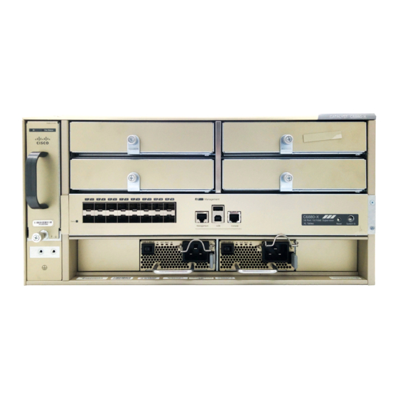
C H A P T E R Product Overview The Catalyst 6880-X switch is an extensible fixed-aggregation switch supporting redundant power supplies and slots for up to four optional port card modules. The chassis has 16 fixed 10-Gigabit SFP+, 1-Gigabit SFP, or 100BASE-FX SFP ports. - Page 14 Product Overview Front Panel Components • Management port • USB ports • Console port • System reset button • LEDs • Fan tray Figure 1: Catalyst 6880-X Switch Catalyst 6880-X Switch Hardware Installation Guide OL-30827-02...
-
Page 15: Sfp And Sfp+ Transceiver Module Ports
All ports support 1-Gigabit SFP, 10-Gigabit SFP+, or 100BASE-FX fiber-optic SFP modules. The ports also support Cisco Trust Security (CTS) and virtual switch link (VSL) and can operate as an Instant Access (AI) Parent in both 1-Gigabit and 10-Gigabit modes. -
Page 16: Half-Wide Modular Slots
"Installing the Modular Port Card" chapter. The chassis is delivered with modular slot blank covers already installed, which must remain installed if the port cards are not used. The slots are numbered as shown in the following figure. Figure 3: Numbering of the Port Card Slots Catalyst 6880-X Switch Hardware Installation Guide OL-30827-02... -
Page 17: Port Card Overview
1-Gigabit SFPs, 10-Gigabit SFP+, or 100BASE-FX fiber-optic modules. C6880-X-16P10G Multirate port card with XL tables. This module has 16 10-Gigabit, 1-Gigabit, or 100BASE-FX fiber-optic slots, which support 1-Gigabit SFPs, 10-Gigabit SFP+, or 100BASE-FX fiber-optic modules. C6880-X-CVR-E Blank module. Catalyst 6880-X Switch Hardware Installation Guide OL-30827-02... -
Page 18: Power Supply Slots
The chassis is delivered with power supplies already installed in the power supply slots. If only one power supply is ordered, then a blank cover is installed in the empty power supply slot, which must remain installed if a power supply is not installed. Catalyst 6880-X Switch Hardware Installation Guide OL-30827-02... -
Page 19: Management Port
The USB Type A port is the only external storage interface for this switch. The port is connected to the route processor, which allows the Cisco IOS software to access the port. The port supports Cisco USB flash drives with capacities from 128 MB to 8 GB (USB devices with port densities of 128 MB, 256 MB, 1 GB, 4 GB, and 8 GB are supported). -
Page 20: Console Port
Modules inserted in the port card module slots include their own LEDs. Related Topics System Status LED, on page 9 System ID LED, on page 9 SFP+ Port LEDs, on page 10 Catalyst 6880-X Switch Hardware Installation Guide OL-30827-02... -
Page 21: System Status Led
Port card has triggered a major environmental alarm, or the system is powering System ID LED The System ID (blue beacon) LED can be provisioned by the operator to indicate that the switch needs attention. Catalyst 6880-X Switch Hardware Installation Guide OL-30827-02... -
Page 22: Id Led On The Modular Port Card
LEDs, and the second LED in each pair indicates the status of the lower (even-numbered) port. Odd-numbered ports, left to right: 1, 3, 5, 7, 9, 11, 13, and 15 Catalyst 6880-X Switch Hardware Installation Guide OL-30827-02... -
Page 23: Management Port Led
Port is provisioned, but administratively not operational. Green Port is linked up. Alternating green and amber A port fault is detected, or the port beacon has been provisioned by the operator. Related Topics LED Indicators, on page 8 Catalyst 6880-X Switch Hardware Installation Guide OL-30827-02... -
Page 24: Fan Tray Leds
Table 8: Fan Tray Fan Status LED Indicator Color/State Description The fan tray is not receiving power; the fans have stopped. Green All fans are operating normally. The fan tray has a failure. Catalyst 6880-X Switch Hardware Installation Guide OL-30827-02... -
Page 25: Ac-Input Power Supply Leds
DC output current is at acceptable level. Blinking green DC output current is outside valid range. FAULT Solid red Malfunction has occurred. Blinking blue The power supply needs attention, activated by operator. Related Topics LED Indicators, on page 8 Catalyst 6880-X Switch Hardware Installation Guide OL-30827-02... -
Page 26: Dc-Input Power Supply Leds
Output DC current is at acceptable level. Blinking green Output DC current is outside valid range. FAULT Power supply unit is functioning normally. FAULT Blinking red The unit has failed self-diagnostic test or is not operational. Catalyst 6880-X Switch Hardware Installation Guide OL-30827-02... -
Page 27: Rear Panel
Product Overview Rear Panel Color/State Description Blinking blue The power supply needs attention, activated by operator. Related Topics LED Indicators, on page 8 Rear Panel Figure 9: Rear Panel Rear panel of the switch Catalyst 6880-X Switch Hardware Installation Guide OL-30827-02... -
Page 28: Multirate Port Card With Standard Tables. This Module Has
Product Overview Rear Panel Catalyst 6880-X Switch Hardware Installation Guide OL-30827-02... -
Page 29: Preparing For Installation
These sections describe some of the basic site requirements that you should be aware of as you prepare to install your switch, including the following: • Environmental factors can adversely affect the performance and longevity of your system. Catalyst 6880-X Switch Hardware Installation Guide OL-30827-02... -
Page 30: Temperature
Failure to observe these guidelines may damage the chassis' internal components. Note The Catalyst 6880-X switches are equipped with internal air temperature sensors that trigger a minor alarm at 104°F (40°C) and trigger a major alarm at 131°F (55°C). Catalyst 6880-X Switch Hardware Installation Guide... -
Page 31: Air Flow
Air Flow Air Flow The Catalyst 6880-X switch is designed to be installed in an environment where there is a sufficient volume of air available to cool the baseboard and other boards in the chassis, any installed modules, and power supplies. -
Page 32: Cooling With The Fan Tray
Cooling with the Fan Tray The chassis fan tray provides cooling air for the Catalyst 6880-X switch chassis and components. If an individual fan within the fan tray fails, the Fan Status LED turns red. Individual fans within a fan tray cannot be replaced;... -
Page 33: Altitude
The Catalyst 6880-X switch is rated to operate at altitudes from 0 to 6500 feet (0 to 2000 meters) and can be stored at altitudes of –200 to 10,000 feet (–60 to 3000 meters). -
Page 34: Power Source Interruptions
• Copy machines • Air conditioners • Vacuum cleaners • Space heaters • Power tools • Teletype machines • Laser printers • Facsimile machines • Any other motorized equipment Catalyst 6880-X Switch Hardware Installation Guide OL-30827-02... -
Page 35: System Grounding
Commercial building contains a mix Medium to High Best grounding practices must be closely of information technology equipment followed. and industrial equipment, such as welding. Catalyst 6880-X Switch Hardware Installation Guide OL-30827-02... -
Page 36: Catalyst 6880-X Switch Hardware Installation Guide
Category 5e, Category 6, and Category 6a cables can store large levels of static electricity because of the dielectric properties of the materials used in their construction. Always ground the cables (especially in new cable runs) to a suitable and safe earth ground before connecting them to the module. Catalyst 6880-X Switch Hardware Installation Guide OL-30827-02... -
Page 37: Maintaining Safety With Electricity
• Use the correct external power source. Operate the product only from the type of power source indicated on the electrical ratings label. If you are not sure of the type of power source required, consult the Cisco Technical Assistance Center or a local electrician. -
Page 38: Preventing Electrostatic Discharge Damage
(identified by the ground symbol next to the connector) somewhere on the front panel. If you have an older Catalyst 6880-X chassis equipped with a plastic banana plug connector, it is recommend that you use either the supplied ESD grounding wrist strap (with a metal clip) or an ESD grounding wrist strap equipped with an alligator clip. -
Page 39: Power Requirements
Be aware when selecting a UPS that some UPS models that use ferroresonant technology can become unstable when operating with the Catalyst 6880-X switch power supplies which use power factor correction (PFC). This can cause the output voltage waveform to the switch to become distorted resulting in an undervoltage situation in the system. -
Page 40: Power Connection Guidelines For Ac-Powered Systems
Power Connection Guidelines for AC-Powered Systems This section provides the basic guidelines for connecting the Catalyst 6880-X switch AC power supplies to the site power source: • Each chassis power supply should have a separate, dedicated branch circuit. -
Page 41: Cabling Requirements
We strongly recommend that power cabling runs and other potential noise sources be located as far away Caution as practical from LAN cabling that terminates on Cisco equipment. In situations where this type of long parallel cable runs exist and cannot be separated by at least 3.3 feet (1 meter), we recommend that you shield these potential noise sources. -
Page 42: Catalyst 6880-X Switch Hardware Installation Guide
• Dedicated (separate) circuits for redundant power supplies • UPS for power failures • DC systems: Proper gauge wire and lugs Grounding evaluation: • Circuit breaker size • CO ground (AC- and DC-powered systems) Catalyst 6880-X Switch Hardware Installation Guide OL-30827-02... -
Page 43: Catalyst 6880-X Switch Hardware Installation Guide
AC source or DC source circuit. Note For UPS for power failures, refer to the power supply’s kVA rating as a sizing criteria in determining the output required by the UPS. Catalyst 6880-X Switch Hardware Installation Guide OL-30827-02... -
Page 44: Catalyst 6880-X Switch Hardware Installation Guide
Preparing for Installation Site Preparation Checklist Catalyst 6880-X Switch Hardware Installation Guide OL-30827-02... -
Page 45: Installing The Switch
C H A P T E R Installing the Switch This chapter describes how to install a Catalyst 6880-X switch. Pointers within the overall chassis installation procedures point to separate installation procedures that cover installing various components and assemblies. •... -
Page 46: Safety Warnings
Hazardous voltage or energy is present on the backplane when the system is operating. Use caution when servicing. Statement 1034 Warning This product requires short-circuit (overcurrent) protection, to be provided as part of the building installation. Install only in accordance with national and local wiring regulations. Statement 1045 Catalyst 6880-X Switch Hardware Installation Guide OL-30827-02... -
Page 47: Rack-Mounting Guidelines
2-15 to verify that all site planning activities were completed. Rack-Mounting Guidelines The Catalyst 6880-X switch is designed to be installed in standard 19-inch racks. Note Before rack-mounting the switch, ensure that the equipment rack complies with the following guidelines: •... -
Page 48: Unpacking The Switch
• Rack-mount shelf kit is provided that includes brackets and a tray to support the chassis when it is installed on a rack. Chassis Installation Kits and Cable Guides The Catalyst 6880-X chassis ships with an accessory kit, which includes chassis installation kits and cable guides: • Standard 19-inch rack-mount L brackets (factory-installed on the chassis). Associated rack-mounting hardware is included in the accessory kit. -
Page 49: Installing The Switch Chassis
L Brackets on the Chassis The Catalyst 6880-X switch chassis is shipped with two L brackets installed toward the front of each side of the chassis, as shown in the following figure. -
Page 50: Installing The Rack-Mount Shelf Kit
Before installing the chassis, you should install the rack-mount shelf kit that is included as part of the accessory kit. The rack-mount shelf kit is shipped as part of the Catalyst 6880-X switch accessory kit. It contains two shelf brackets, a support shelf, and screws. The shelf brackets attach directly to the rack and help support the weight of the chassis. -
Page 51: Installing The Shelf Brackets And Shelf- 17.5 In. (44.45 Cm) Opening
Position the support flange of the left shelf bracket on the front of the left rail, as shown in the figure. (Alternatively, you can position the support flange of the left shelf bracket on the back of the left rail.) Step 2 Secure the shelf bracket to the rack by using four screws. Catalyst 6880-X Switch Hardware Installation Guide OL-30827-02... -
Page 52: Installing The Shelf Brackets And Shelf- 17.75 In. (45.09 Cm) Opening
Installing the Shelf Brackets and Shelf— 17.75 in. (45.09 cm) Opening Before You Begin Review the following illustration and table. Figure 14: Installing the Shelf Brackets on a Rack with a 17.75 in. (45.09 cm) Opening Catalyst 6880-X Switch Hardware Installation Guide OL-30827-02... -
Page 53: Rack-Mounting The Chassis
◦ Reposition the L brackets to align with the first set of holes behind the holes where the L brackets were originally installed (see figure below). ◦ Secure the brackets with the screws. Catalyst 6880-X Switch Hardware Installation Guide OL-30827-02... -
Page 54: Catalyst 6880-X Switch Hardware Installation Guide
10-32 or 12-24. If the rack post holes are unthreaded, install eight or ten (four or five on each side) either 10-32 or 12-24 clip or cage nuts over the rack post holes to accept the installation screws. Catalyst 6880-X Switch Hardware Installation Guide OL-30827-02... -
Page 55: Catalyst 6880-X Switch Hardware Installation Guide
L bracket holes, rack post holes, and into the clip nuts to secure the cable guides and the chassis to the rack post. Tighten the screws securely. Figure 16: Installing the Cable Mount Guides Cable guide Catalyst 6880-X Switch Hardware Installation Guide OL-30827-02... -
Page 56: Catalyst 6880-X Switch Hardware Installation Guide
• Connecting to the switch console port. See Connecting the Switch Console Port, on page • Connecting to the uplink ports. • Powering-up the chassis and verifying the installation. See Verifying Switch Chassis Installation, on page Catalyst 6880-X Switch Hardware Installation Guide OL-30827-02... -
Page 57: Establishing The System Ground
Installing the Switch Establishing the System Ground Establishing the System Ground This section describes how to connect a system ground to the Catalyst 6880-X switch. Installations that rely solely on system grounding using only an AC third-prong ground run a substantially Caution greater risk of equipment problems and data corruption than those installations that use both the AC third-prong ground and a properly installed system ground. -
Page 58: Connecting The System Ground
Crimp the grounding wire in the barrel of the grounding lug. Verify that the ground wire is securely attached to the ground lug. Step 4 Place the grounding wire lug against the grounding pad, making sure that there is solid metal-to-metal contact. Catalyst 6880-X Switch Hardware Installation Guide OL-30827-02... -
Page 59: Installing The Power Supplies In The Switch Chassis
Connect to the port using the RJ-45-to-RJ-45 cable and RJ-45-to-DB-25 DTE adapter or RJ-45-to-DB-9 DTE adapter (labeled "Terminal"). Step 2 Position the cable in the cable guide (if installed). Make sure there are no sharp bends in the cable. Catalyst 6880-X Switch Hardware Installation Guide OL-30827-02... -
Page 60: Connecting The Uplink Ports
SFP module slot. The SFP modules have LC connectors for fiber-optic connections or RJ-45 connectors for copper connections. For Cisco SFP and SFP+ transceiver modules documentation, including compatibility matrixes, refer to this URL: http://www.cisco.com/en/US/products/hw/modules/ps5455/products_device_support_tables_list.html... -
Page 61: Catalyst 6880-X Switch Hardware Installation Guide
If the module has a bale-clasp latch, close it to lock the SFP transceiver module in place. If you are inserting the SFP transceiver module in the lower ports, you need to invert the module. Note Step 6 Remove the SFP dust plugs and save. Catalyst 6880-X Switch Hardware Installation Guide OL-30827-02... -
Page 62: Removing Sfp Or Sfp+ Transceiver Modules
Step 5 Grasp the SFP transceiver module, and carefully remove it from the slot. Step 6 Place the SFP transceiver module in an antistatic bag or other protective environment. Catalyst 6880-X Switch Hardware Installation Guide OL-30827-02... -
Page 63: Verifying Switch Chassis Installation
Online Diagnostics The switch running Cisco IOS has many levels of online diagnostic capabilities. The online diagnostics are divided into four categories: • Bootup—Bootup diagnostics automatically run during bootup, module OIR, or switchover to a backup supervisor engine. -
Page 64: Catalyst 6880-X Switch Hardware Installation Guide
Installing the Switch Online Diagnostics Catalyst 6880-X Switch Hardware Installation Guide OL-30827-02... -
Page 65: Installing And Removing Power Supplies
Installing Power Supplies, page 55 • Removing Power Supplies, page 59 • Finding the Serial Number, page 61 Power Supply Overview You can install two types of power supplies in the chassis: • C6880-X-3KW-AC-Input power supply Catalyst 6880-X Switch Hardware Installation Guide OL-30827-02... -
Page 66: Catalyst 6880-X Switch Hardware Installation Guide
• C6880-X-3KW-DC-Input power supply Figure 21: C6880-X-3KW-AC-Input Power Supply Figure 22: C6880-X-3KW-DC-Input Power Supply The Catalyst 6880-X switch chassis has two slots in which you can install power supplies using any of the following combinations: • Two AC-input power supplies •... -
Page 67: Installing Power Supplies
6 AWG copper conductor. For installations outside the U.S., consult your local and national electrical codes. The length of the grounding wire depends on the proximity of the switch to proper grounding facilities. Catalyst 6880-X Switch Hardware Installation Guide OL-30827-02... -
Page 68: Inserting The Power Supply
Slide the unit all the way into the power supply bay until the release latch on the front of the power supply clicks and prevents you from moving the power supply in or out of the chassis. Figure 23: Installing the Power Supply AC power supply Catalyst 6880-X Switch Hardware Installation Guide OL-30827-02... -
Page 69: Connecting To The Power Source
Warning Before performing any of the following procedures, ensure that power is removed from the DC circuit. Statement 1003 Catalyst 6880-X Switch Hardware Installation Guide OL-30827-02... -
Page 70: Connecting To An Ac Power Source
Turn off the power at the circuit breakers for the portions of the DC grid power that you are connecting to and verify that all of the LEDs on the power supplies are off. Catalyst 6880-X Switch Hardware Installation Guide OL-30827-02... -
Page 71: Removing Power Supplies
The LEDs should flash and then the Output LED should turn on in addition to the Input LEDs. If the FAULT LED is on or flashing, call Cisco TAC for assistance. Removing Power Supplies... -
Page 72: Catalyst 6880-X Switch Hardware Installation Guide
If you intend to operate the switch without installing another power supply in the empty slot, then Caution you must reinstall the blank cover over the empty power supply slot to ensure proper air flow in the system and for safety reasons. Catalyst 6880-X Switch Hardware Installation Guide OL-30827-02... -
Page 73: Finding The Serial Number
Finding the Serial Number If you contact Cisco Technical Assistance, you need to know the serial number. These figures show where the serial number is located. You can also use the show version privileged EXEC command to see the serial number. -
Page 74: Catalyst 6880-X Switch Hardware Installation Guide
Installing and Removing Power Supplies Finding the Serial Number Catalyst 6880-X Switch Hardware Installation Guide OL-30827-02... -
Page 75: Installing The Modular Port Card
1-Gigabit SFPs, 10-Gigabit SFP+, or 100BASE-FX fiber-optic modules. C6880-X-16P10G Multirate port card with XL tables. This module has 16 10-Gigabit, 1-Gigabit, or 100BASE-FX fiber-optic slots, which support 1-Gigabit SFPs, 10-Gigabit SFP+, or 100BASE-FX fiber-optic modules. C6880-X-CVR-E Blank module. Catalyst 6880-X Switch Hardware Installation Guide OL-30827-02... -
Page 76: Modular Port Card Leds
For information on the modular port card LEDs, see these sections : • SFP+ Port LEDs, on page 10 • Status LED on the Modular Port Card, on page 9 • ID LED on the Modular Port Card, on page 10 Catalyst 6880-X Switch Hardware Installation Guide OL-30827-02... -
Page 77: Modular Port Card Installation
Attach an ESD-preventive wrist strap to your wrist and to an earth ground surface. Step 2 Loosen the screw counter-clockwise on the blank module, and pull out the blank module from the chassis. Figure 27: Removing the Blank Module Catalyst 6880-X Switch Hardware Installation Guide OL-30827-02... -
Page 78: Catalyst 6880-X Switch Hardware Installation Guide
Figure 29: Installing the Modular Port Card Step 6 Close the latch on the extraction handle by pressing the lever until you hear a click, and it latches. Catalyst 6880-X Switch Hardware Installation Guide OL-30827-02... -
Page 79: Installing Sfp And Sfp+ Transceiver Modules In The Port Card
If the module has a bale-clasp latch, close it to lock the SFP transceiver module in place. If you are inserting the SFP transceiver module in the lower ports, you need to invert the module as Note shown above. Catalyst 6880-X Switch Hardware Installation Guide OL-30827-02... -
Page 80: Removing Sfp Or Sfp+ Modules From The Modular Port Card
If the module has a bale-clasp latch, use the SFP removal tool. Use the optical cable release side of the tool and apply pressure to release the cable latch, and disconnect the cable from the SFP transceiver module. Figure 32: Removing the Cable from the SPF Module Catalyst 6880-X Switch Hardware Installation Guide OL-30827-02... - Page 81 Step 4 Grasp the SFP or SFP+ transceiver module, and carefully remove it from the slot. Step 5 Place the SFP or SFP+ transceiver module in an antistatic bag or other protective environment. Catalyst 6880-X Switch Hardware Installation Guide OL-30827-02...
-
Page 82: Removing A Modular Port Card
Removing a Modular Port Card Removing a Modular Port Card Procedure Step 1 Attach an ESD-preventive wrist strap to your wrist and to an earth ground surface. Figure 34: Attaching an ESD Strap Catalyst 6880-X Switch Hardware Installation Guide OL-30827-02... - Page 83 Place the port card that you removed in an antistatic bag or other protective environment. Note You can close the latch so it locks, and use the handle to carry the port card module. Catalyst 6880-X Switch Hardware Installation Guide OL-30827-02...
-
Page 84: Finding The Modular Port Card Serial Number
Finding the Modular Port Card Serial Number If you contact Cisco Technical Assistance, you need to know the port card serial number. This figure shows where the serial number is located. You can also use the show version privileged EXEC command to see the serial number. -
Page 85: Replacing The Fan Tray
The fans might still be turning when you remove the fan from the chassis. Keep fingers, screwdrivers, Warning and other objects away from the openings in the fan’s housing. Statement 263 Procedure Step 1 Locate the fan tray as shown in the figure. Catalyst 6880-X Switch Hardware Installation Guide OL-30827-02... - Page 86 When removing the fan tray, keep your hands and fingers away from the spinning fan blades. Let Caution the fan blades stop completely before you remove the fan tray. Catalyst 6880-X Switch Hardware Installation Guide OL-30827-02...
-
Page 87: Installing The Fan Tray
Push the fan tray into the chassis until the power connector seats in the backplane and the captive installation screw make contact with the chassis. Step 4 Tighten the captive installation screw. Related Topics Cooling with the Fan Tray , on page 20 Catalyst 6880-X Switch Hardware Installation Guide OL-30827-02... -
Page 88: Checking The Installation
Verify that the FAN STATUS LED is green. If the LED is red, one or more of the fans are faulty. If after several attempts the fans do not operate or if you experience trouble with the installation (for instance, if the captive installation screws do not align with the chassis holes), contact a Cisco customer service representative for assistance. -
Page 89: Finding The Fan Serial Number
Finding the Fan Serial Number If you contact Cisco Technical Assistance, you need to know the fan serial number. This figure shows where the serial number is located. You can also use the show version privileged EXEC command to see the serial number. - Page 90 Replacing the Fan Tray Finding the Fan Serial Number Catalyst 6880-X Switch Hardware Installation Guide OL-30827-02...
-
Page 91: Appendix A Technical Specifications
Certified for operation: 32° to 104°F (0° to 40°C) Designed and tested for operation: 32° to 131°F (0° to 55°C) The Catalyst 6880-X switch is equipped with Note internal air temperature sensors that generate a minor alarm when triggered at 104°F (40°C) and generate a major alarm when... - Page 92 • Width = 17.35 in. (44.07 cm) • Depth= 23 in. (58.42 cm) • Chassis requires 5 rack units (RUs) • The Catalyst 6880-X switch is designed to install in standard 19-inch equipment racks that meet ANSI/EIA 310-D, IEC 60297, and ETS 300-199 standards.
-
Page 93: Power Supply Module Specifications
Power Supply Module Specifications Environmental Specification Airflow C6880-X-FAN Note The airflow in the Catalyst 6880-X switch chassis is from right to left. See Site Requirements, on page 17 for recommended separations between walls and the chassis air intake and air exhaust and between the air exhaust of one chassis with the air intake of another chassis. -
Page 94: 3000 W Power Supply Ac Power Cords
Type Rating Illustration Argentina IRAM 2073 16 A, 250 Figure 41: CAB-IR2073-C19-AR= (Argentina) , on page 85 Australia, New Zealand AU20S3 16 A, 250 Figure 42: CAB-AC-16A-AUS= (Australia, New Zealand), on page 85 Catalyst 6880-X Switch Hardware Installation Guide OL-30827-02... - Page 95 Figure 55: CAB-7513ACSA (South Africa), on page 89 Switzerland SEV 5934-2 16 A, 250 Figure 56: CAB-ACS-16= (Switzerland), on Type 23 page 90 3 The 3000 W power supply operating on 110 VAC delivers 1400 W. Catalyst 6880-X Switch Hardware Installation Guide OL-30827-02...
- Page 96 4 The PDU power cable is designed for users who power their switch from a PDU. The end of the cable that plugs into the chassis power supply has a C19 connector; the other end of the cable that connects to the PDU has a C20 connector . Catalyst 6880-X Switch Hardware Installation Guide OL-30827-02...
- Page 97 Technical Specifications 3000 W Power Supply AC Power Cords AC Power Cord Illustrations Figure 41: CAB-IR2073-C19-AR= (Argentina) Figure 42: CAB-AC-16A-AUS= (Australia, New Zealand) Figure 43: UCSB-CABL-C19-BRZ= (Brazil) Figure 44: CAB-AC16A-CH= (People's Republic of China) Catalyst 6880-X Switch Hardware Installation Guide OL-30827-02...
- Page 98 Technical Specifications 3000 W Power Supply AC Power Cords Figure 45: CAB-AC-2500W-EU= (Continental Europe) Figure 46: CAB-SABS-C19-IND= (India) Figure 47: CAB-AC-2500W-INT= (International) Catalyst 6880-X Switch Hardware Installation Guide OL-30827-02...
- Page 99 Technical Specifications 3000 W Power Supply AC Power Cords Figure 48: CAB-AC-2500W-ISRL= (Israel) Figure 49: CAB-7513ACI= (Italy) Figure 50: CAB-AC-2500W-US1= (Japan, North America [Nonlocking Plug] 200 to 240 VAC operation) Catalyst 6880-X Switch Hardware Installation Guide OL-30827-02...
- Page 100 Technical Specifications 3000 W Power Supply AC Power Cords Figure 51: CAB-AC-C6K-TWLK= (Japan, North America [Locking Plug] 200 to 240 VAC operation) Catalyst 6880-X Switch Hardware Installation Guide OL-30827-02...
- Page 101 The form factor for these two plugs differ but functionally they are the same. Note Figure 52: CAB-7513AC= (Japan, North America100 to120 VAC operation) Figure 53: CAB- L520P - C19 -US= (North America) Figure 54: CAB-C19-CBN= (PDU) Figure 55: CAB-7513ACSA (South Africa) Catalyst 6880-X Switch Hardware Installation Guide OL-30827-02...
-
Page 102: Fan Module Specifications
Airflow 250 cfm Chassis and Module Power and Heat Values Module Module Module AC-Input AC Heat DC Input DC Heat Diss Type Current (A) Power Power Diss Power (BTU/HR) (Watts) (Watts) (BTU/HR) (Watts) Catalyst 6880-X Switch Hardware Installation Guide OL-30827-02... - Page 103 660 W 713 W 2432 697 W 2432 BTU/HR 6880-X BTU/HR Catalyst 12.6 A 630 W 680 W 2321 680 W 2321 BTU/HR 6880-X-LE BTU/HR 5 Includes fan tray 6 Includes fan tray Catalyst 6880-X Switch Hardware Installation Guide OL-30827-02...
- Page 104 Technical Specifications Chassis and Module Power and Heat Values Catalyst 6880-X Switch Hardware Installation Guide OL-30827-02...
-
Page 105: Appendix B Module Connectors And Cable Specifications
To comply with GR-1089 intrabuilding and lightning immunity requirements, you must use a foil Caution twisted-pair (FTP) cable that is properly grounded at both ends. Catalyst 6880-X Switch Hardware Installation Guide OL-30827-02... -
Page 106: Lc Connector
Cables and Adapters SFP Module Cables For cabling specifications, refer to the Cisco SFP and SFP+ Transceiver Module Installation Notes. Each port must match the wave-length specifications on the other end of the cable, and the cable must not exceed the stipulated cable length. Copper 1000BASE-T SFP module transceivers use standard four twisted-pair, Category 5 cable at lengths up to 328 feet (100 meters). -
Page 107: Cable Pinouts
Module Connectors and Cable Specifications Cable Pinouts Cable Pinouts Figure 59: Four Twisted-Pair Straight-Through Cable Schematic Figure 60: Four Twisted-Pair Crossover Cable Schematic Figure 61: Two Twisted-Pair Straight-Through Cable Schematic Figure 62: Two Twisted-Pair Crossover Cable Schematic Catalyst 6880-X Switch Hardware Installation Guide OL-30827-02... -
Page 108: Console Port Adapter Pinouts
PC. You need to provide a RJ-45-to-DB-25 female DTE adapter to connect the switch console port to a terminal. You can order the kit (part number ACS-DSBUASYN=) from Cisco. Table 14: Console Port Signaling with a DB-9 Adapter... -
Page 109: Console Port Mode 2 Signaling And Pinouts
Table 16: Port Mode 2 Signaling and Pinouts (Port Mode Switch Out) Console Port Console Device Pin (signal) Input/Output 1 (RTS) Output 2 (DTR) Output 3 (RxD) Input 4 (GND) 5 (GND) 6 (TxD) Output 7 (DSR) Input 8 (CTS) Input Catalyst 6880-X Switch Hardware Installation Guide OL-30827-02... -
Page 110: Cleaning The Fiber-Optic Connectors
• Does not use force or quick movements when connecting the fiber-optic connectors in the adapters. • Covers the connectors and adapters to keep the inside of the adapters or the surface of the connectors from getting dirty when not using the connectors or while cleaning the chassis. Catalyst 6880-X Switch Hardware Installation Guide OL-30827-02... -
Page 111: How To Clean The Fiber-Optic Connectors
Remove any residual dust from the faceplate with clean, dry, oil-free compressed air. Step 3 Use a magnifying glass or inspection microscope to inspect the ferrule at an angle. Do not look directly into the aperture. Repeat the process if any contamination is detected. Catalyst 6880-X Switch Hardware Installation Guide OL-30827-02... - Page 112 Module Connectors and Cable Specifications How to Clean the Fiber-Optic Connectors Catalyst 6880-X Switch Hardware Installation Guide OL-30827-02...
-
Page 113: Appendix C Repacking The Switch
A P P E N D I X Repacking the Switch If you need to return or move the Catalyst 6880-X switch chassis, follow these steps to repack the switch using the original packaging material. Procedure Step 1 Set the chassis in the bottom pallet. - Page 114 Fold the outside carton down over the top and seal with packing tape. Step 9 Wrap three packing straps tightly around the top and bottom of the package to hold the outside carton and the bottom pallet together. Figure 65: Final Package Catalyst 6880-X Switch Hardware Installation Guide OL-30827-02...
-
Page 115: Troubleshooting
Troubleshooting Note The information in this chapter applies to all Catalyst 6880-X switches unless otherwise noted. Problems with the initial startup are often caused by a switching module that has become dislodged from the backplane or a power supply that has been disconnected from the power cord connector. Although temperature conditions above the maximum acceptable level rarely occur at initial startup, you might encounter these conditions during extended operation. -
Page 116: Solving Problems At The System Component Level
Troubleshooting the Power Supply If the INPUT OK LED does not light after you turn on the power switch, follow these steps to isolate a power subsystem problem: Catalyst 6880-X Switch Hardware Installation Guide OL-30827-02... -
Page 117: Troubleshooting The Fan Tray
Step 1 Verify that the FAN LED on the fan tray is green. If the FAN LED is not green, see Contacting Cisco Customer Service, on page 106 to determine whether or not the power subsystem is functioning properly. Step 2 Check to determine if the FAN LED is red. -
Page 118: Status Led Indicators
If you are unable to solve a startup problem after using the troubleshooting suggestions in this chapter, contact a Cisco customer service representative for assistance and additional instructions. Before you call, have the following information ready to help your service provider assist you as quickly as possible: •... -
Page 119: Finding The Serial Number
Finding the Serial Number If you contact Cisco Technical Assistance, you need to know the switch serial number. The figure shows where the serial number is located. You can also use the show version privileged EXEC command to see the serial number. - Page 120 Troubleshooting Finding the Serial Number Catalyst 6880-X Switch Hardware Installation Guide OL-30827-02...
-
Page 121: Appendix E Installing The Usb Drivers
Installing the Cisco Microsoft Windows XP USB Driver Procedure Step 1 Obtain the Cisco USB console driver file from the Cisco.com web site and unzip it. Note You can download the driver file from the Cisco.com site for downloading the switch software. -
Page 122: Installing The Cisco Microsoft Windows 2000 Usb Driver
Installing the Cisco Microsoft Windows 2000 USB Driver Procedure Step 1 Obtain the Cisco USB console driver file from the Cisco.com web site and unzip it. You can download the driver file from the Cisco.com site for downloading the switch software. Note Step 2 Double-click the setup.exe file. -
Page 123: Using The Setup.exe Program
Installing the USB Drivers Uninstalling the Cisco Microsoft Windows Vista and Windows 7 USB Driver Using the Setup.exe Program Before You Begin Disconnect the switch console terminal before uninstalling the driver. Procedure Step 1 Run setup.exe for Windows 32-bit or setup(x64).exe for Windows-64bit. Click Next. - Page 124 Installing the USB Drivers Uninstalling the Cisco Microsoft Windows Vista and Windows 7 USB Driver Step 5 When the InstallShield Wizard Completed window appears, click Finish. Catalyst 6880-X Switch Hardware Installation Guide OL-30827-02...
Need help?
Do you have a question about the Catalyst 6880-X and is the answer not in the manual?
Questions and answers