Table of Contents
Advertisement
Quick Links
Cisco Catalyst 6807-XL Switch Hardware Installation Guide
First Published: December 20, 2013
Last Modified: July 02, 2014
Americas Headquarters
Cisco Systems, Inc.
170 West Tasman Drive
San Jose, CA 95134-1706
USA
http://www.cisco.com
Tel: 408 526-4000
800 553-NETS (6387)
Fax: 408 527-0883
Text Part Number: OL-30656-01
Advertisement
Table of Contents
Troubleshooting

Subscribe to Our Youtube Channel
Related Manuals for Cisco Catalyst 6807-XL


Summary of Contents for Cisco Catalyst 6807-XL
- Page 1 Cisco Catalyst 6807-XL Switch Hardware Installation Guide First Published: December 20, 2013 Last Modified: July 02, 2014 Americas Headquarters Cisco Systems, Inc. 170 West Tasman Drive San Jose, CA 95134-1706 http://www.cisco.com Tel: 408 526-4000 800 553-NETS (6387) Fax: 408 527-0883...
- Page 2 Cisco and the Cisco logo are trademarks or registered trademarks of Cisco and/or its affiliates in the U.S. and other countries. To view a list of Cisco trademarks, go to this URL: www.cisco.com/go/trademarks . Third-party trademarks mentioned are the property of their respective owners. The use of the word partner does not imply a partnership relationship between Cisco and any other company.
-
Page 3: Table Of Contents
Power Supply Module LEDs Power Supply Converter LEDs Rear Panel Backplane Bandwidth Clock and VTT Module Preparing for Installation C H A P T E R 2 Safety Warnings Site Requirements Temperature Cisco Catalyst 6807-XL Switch Hardware Installation Guide OL-30656-01... - Page 4 Verifying the Switch Chassis Installation Online Diagnostics Connecting the Supervisor Engine Console Port Installing Transceivers and Module Connectors Removing and Replacing FRUs C H A P T E R 4 Online Insertion and Removal Cisco Catalyst 6807-XL Switch Hardware Installation Guide OL-30656-01...
- Page 5 Pluggable Transceivers 1-GB Transceivers 10-GB Transceivers 40-GB Transceivers WDM Transceivers Module Connectors RJ-45 Connector SC Connector LC Connector MTP-12 Connector Cleaning the Fiber-Optic Connectors Guidelines How to Clean the Fiber-Optic Connectors Cable Specifications Cisco Catalyst 6807-XL Switch Hardware Installation Guide OL-30656-01...
- Page 6 A P P E N D I X E Getting Started Solving Problems at the System Component Level Identifying Startup Problems Troubleshooting the Power Supply Module Troubleshooting the Fan Tray Contacting Cisco Customer Service Finding Serial Numbers Cisco Catalyst 6807-XL Switch Hardware Installation Guide OL-30656-01...
-
Page 7: Preface
A vertical line, called a pipe, indicates a choice within a set of keywords or arguments. [x | y] Optional alternative keywords are grouped in brackets and separated by vertical bars. Cisco Catalyst 6807-XL Switch Hardware Installation Guide OL-30656-01... - Page 8 Use the statement number provided at the end of each warning to locate its translation in the translated safety warnings that accompanied this device. Statement 1071 SAVE THESE INSTRUCTIONS Cisco Catalyst 6807-XL Switch Hardware Installation Guide viii OL-30656-01...
-
Page 9: Related Documentation
Obtaining Documentation and Submitting a Service Request For information on obtaining documentation, submitting a service request, and gathering additional information, see the monthly What's New in Cisco Product Documentation, which also lists all new and revised Cisco technical documentation, at: http://www.cisco.com/c/en/us/td/docs/general/whatsnew/whatsnew.html... - Page 10 Preface Obtaining Documentation and Submitting a Service Request Cisco Catalyst 6807-XL Switch Hardware Installation Guide OL-30656-01...
-
Page 11: Product Overview
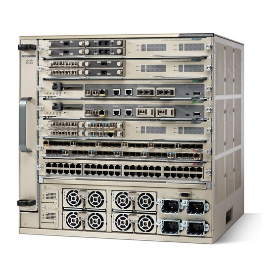
• Fan tray • Five Module slots • Two supervisor engine slots • Four power supply bays • Four power entry modules • Two power supply converter modules • System On/Off switch Cisco Catalyst 6807-XL Switch Hardware Installation Guide OL-30656-01... -
Page 12: Chassis
Supervisor engine slot System ground connector System On/Off switch Chassis The Cisco Catalyst 6807-XL switch chassis has seven horizontal slots, of which five are module slots and two are supervisor engine slots. Related Topics Rack-Mounting the Chassis, on page 37... -
Page 13: Supervisor Engine
Catalyst 6500 Series Switch Supervisor Engine Guide. Related Topics Connecting the Supervisor Engine Console Port , on page 46 Modules The switch supports the following Cisco Catalyst 6500 Series Ethernet modules: • WS-X6704-10GE • WS-X6908-10G-2T and WS-X6908-10G-2TXL • WS-X6748-GE-TX • WS-X6848-TX-2T and WS-X6848-TX-2TXL •... -
Page 14: Fan Tray
• WS-X6716-10G • WS-X6816-10G-2T and WS-X6816-10G-2TXL • WS-X6724-SFP • WS-X6824-SFP-2T and WS-X6824-SFP-2TXL • WS-X6904-40G-2T and WS-X6904-40G-2TXL The switch supports the following Cisco Catalyst 6500 Series service modules: • NAM3 • ASA-SM • WiSM2 • ACE-30 For more information, see the Catalyst 6500 Ethernet Module Installation Guide. -
Page 15: Power Supply Module
The power available to the of a failure. The system power supply system is the sum of power outputs of all configuration is n PSMs +1 redundant PSM. the PSMs in the chassis. Cisco Catalyst 6807-XL Switch Hardware Installation Guide OL-30656-01... - Page 16 PSMs at least two PSMs (2+0) operating in the operating in a redundant mode (2+1). combined mode. 3 Total number of operational PSMs Cisco Catalyst 6807-XL Switch Hardware Installation Guide OL-30656-01...
-
Page 17: Power Entry Module
The PSC converts the 52 V supplied by the PSM to 3.3 V and conducts it to the backplane. The clock module, VTT modules, and module slots (line cards) require 3.3 V. The PSC supports: • Model number C6807-X-3.3V. Cisco Catalyst 6807-XL Switch Hardware Installation Guide OL-30656-01... -
Page 18: Leds
Use the switch LEDs to monitor switch activity and performance. For information about module and supervisor engine LEDs, refer to the Catalyst 6500 Ethernet Module Installation Guide and the Catalyst 6500 Series Switch Supervisor Engine Guide available on Cisco.com. Fan Tray LED The fan tray includes an ID LED and a Fan Status LED, as shown in the following figure. -
Page 19: Power Supply Module Leds
Input AC is present but not within regulation range or AC power was just disconnected and the power supply internal circuitry is still charged Green Power output is OK Green (blinking) Output is in a power limit or over current condition Cisco Catalyst 6807-XL Switch Hardware Installation Guide OL-30656-01... -
Page 20: Power Supply Converter Leds
The A3.3V from the module is within normal range The A3.3V from the module is not within normal range Table 6: ID LED and Description LED Color Meaning Blue Identifies the power supply converter module in the chassis Cisco Catalyst 6807-XL Switch Hardware Installation Guide OL-30656-01... -
Page 21: Rear Panel
These rear panel components are located behind the back plate of the chassis: • Backplane • Clock module • Voltage Termination-Enhanced (VTT-E) module Figure 5: Cisco Catalyst 6807-XL Rear Panel Backplane Bandwidth The backplane supports: Cisco Catalyst 6807-XL Switch Hardware Installation Guide... -
Page 22: Clock And Vtt Module
The switch supports one replaceable clock card with built-in redundancy. The supported model number is CLK-7600. Three replaceable voltage termination (VTT-E) modules, which are rear-serviceable (located behind back-plate) provide reference voltage for bus signals. The supported model number is WS-C6K-VTT-E. Cisco Catalyst 6807-XL Switch Hardware Installation Guide OL-30656-01... -
Page 23: Preparing For Installation
Statement 1017 Only trained and qualified personnel should be allowed to install, replace, or service this equipment. Warning Statement 1030 Cisco Catalyst 6807-XL Switch Hardware Installation Guide OL-30656-01... -
Page 24: Site Requirements
• If the system has been exposed to abnormally cold temperatures, allow a 2-hour warm-up period to bring it to normal operating temperature before turning it on. Failure to observe these guidelines may damage the chassis' internal components. Cisco Catalyst 6807-XL Switch Hardware Installation Guide OL-30656-01... -
Page 25: Air Flow
104°F (40°C) and may cause minor alarms. Cisco Catalyst 6807-XL Switch Hardware Installation Guide OL-30656-01... -
Page 26: Selecting Rack Enclosure Cabinets
777-3300. Chatsworth Products, Inc. The N-Series TeraFrame Network Gen 3 cabinet product line is compatible with the Cisco Catalyst 6807-XL switch. Several product configurations are available to support your specific datacenter airflow strategy: • For hot and cold aisle configurations including aisle containment—Part number NF1U-113C-C42-1 (or alternate sizes). -
Page 27: Humidity
However, if a system is located in an unusually humid location, a dehumidifier should be used to maintain the humidity within an acceptable range. Cisco Catalyst 6807-XL Switch Hardware Installation Guide OL-30656-01... -
Page 28: Altitude
• Ensure that all chassis slots are covered by a metal filler bracket and that an unused power supply bay has a metal cover plate installed. • Ensure that the screws on all peripheral cable connectors are securely fastened to their corresponding connectors on the back of the chassis. Cisco Catalyst 6807-XL Switch Hardware Installation Guide OL-30656-01... -
Page 29: Power Source Interruptions
• Copy machines • Air conditioners • Vacuum cleaners • Space heaters • Power tools • Teletype machines • Laser printers • Facsimile machines • Any other motorized equipment Cisco Catalyst 6807-XL Switch Hardware Installation Guide OL-30656-01... -
Page 30: System Grounding
Commercial building contains a mix Medium to High Best grounding practices must be closely of information technology equipment followed. and industrial equipment, such as welding. Cisco Catalyst 6807-XL Switch Hardware Installation Guide OL-30656-01... - Page 31 Category 5e, Category 6, and Category 6a cables can store large levels of static electricity because of the dielectric properties of the materials used in their construction. Always ground the cables (especially in new cable runs) to a suitable and safe earth ground before connecting them to the module. Cisco Catalyst 6807-XL Switch Hardware Installation Guide OL-30656-01...
-
Page 32: Maintaining Safety With Electricity
• Use the correct external power source. Operate the product only from the type of power source indicated on the electrical ratings label. If you are not sure of the type of power source required, consult the Cisco Technical Assistance Center or a local electrician. -
Page 33: Preventing Electrostatic Discharge Damage
• If you are using a 200 or 240 VAC power source in North America, the circuit must be protected by a two-pole circuit breaker. • The source AC outlet must be within 6 feet (1.8 meters) of the system, and should be easily accessible. Cisco Catalyst 6807-XL Switch Hardware Installation Guide OL-30656-01... -
Page 34: Cabling Requirements
Rack-Mounting Guidelines The Cisco Catalyst 6807-XL Switch is designed to be installed in both open and enclosed racks. The switch can be installed on 19-inch equipment racks. If you are using a 2-post or 4-post 19-inch standard equipment rack, before rack-mounting the switch, ensure that the equipment rack complies with these guidelines: •... -
Page 35: Site Preparation Checklist
Accessory Kit, on page 31 Site Preparation Checklist The following table lists the site-planning activities that you should perform prior to installing the switch. Completing each activity helps ensure a successful switch installation. Cisco Catalyst 6807-XL Switch Hardware Installation Guide OL-30656-01... - Page 36 • UPS for power failures Grounding evaluation • Circuit breaker size • CO ground (AC powered systems) Cable and interface equipment evaluation • Cable type • Connector type • Cable distance limitations • Interface equipment (transceivers) Cisco Catalyst 6807-XL Switch Hardware Installation Guide OL-30656-01...
- Page 37 6 Refer to the power supply'VA rating as a sizing criteria in determining the output required by the UPS. The power supply kVA rating value is listed in the specifications table for each power supply in Appendix A (power supply specifications). Cisco Catalyst 6807-XL Switch Hardware Installation Guide OL-30656-01...
- Page 38 Preparing for Installation Site Preparation Checklist Cisco Catalyst 6807-XL Switch Hardware Installation Guide OL-30656-01...
-
Page 39: Installing The Switch
Install the rack-mount shelves before you install the chassis in the rack. The shelf brackets help support the weight of the chassis. Rack-mounting the chassis Install the chassis in a standard 19-inch rack, either open or enclosed. Cisco Catalyst 6807-XL Switch Hardware Installation Guide OL-30656-01... - Page 40 This unit might have more than one power supply connection. All connections must be removed to Warning de-energize the unit. Statement 1028 Only trained and qualified personnel should be allowed to install, replace, or service this equipment. Warning Statement 1030 Cisco Catalyst 6807-XL Switch Hardware Installation Guide OL-30656-01...
-
Page 41: Accessory Kit
Installation of the equipment must comply with local and national electrical codes.. Statement 1074 Warning Accessory Kit Each Cisco Catalyst 6807-XL Switch chassis ships with an accessory kit. The following are shipped as part of the accessory kit: • Standard 19-inch rack-mount L brackets—The L brackets are factory installed on the left-front and right-front of the chassis. -
Page 42: Unpacking The Switch
• Check the modules in each slot. Ensure that the configuration matches the packing list and that all of the specified interfaces are included. Cisco Catalyst 6807-XL Switch Hardware Installation Guide OL-30656-01... -
Page 43: L Brackets On The Chassis
The rack-mount shelf kit is part of the accessory kit. Install this kit before you install the chassis in the rack. The shelf brackets attach directly to the rack and help support the weight of the chassis while you secure the L brackets to the rack enclosure. Cisco Catalyst 6807-XL Switch Hardware Installation Guide OL-30656-01... -
Page 44: Installing The Shelf And Crossbar Brackets In A 17.5-Inch (44.45 Cm) Opening
You have to rear-mount the shelf and crossbar brackets for a rack with a 17.5-inch rail-to-rail opening. Important Perform these steps: Before You Begin You will require: • Number 1 and Number 2 Phillips screwdrivers • 3/16-inch flat-blade screwdriver • Tape measure and level Cisco Catalyst 6807-XL Switch Hardware Installation Guide OL-30656-01... - Page 45 Five EA screws on each side, to secure the shelf bracket to the rack Left shelf bracket Cross bar bracket Right rail One M3 screw on each side to secure the cross bar bracket to the shelf Right shelf bracket Cisco Catalyst 6807-XL Switch Hardware Installation Guide OL-30656-01...
-
Page 46: Installing The Shelf And Crossbar Brackets In A 17.75 Inch (45.09 Cm) Opening
Align and secure the bracket to the rack by using two EA screws. Step 3 Position the crossbar bracket to the rear of the shelf brackets Align and secure the crossbar bracket to the shelf bracket with one M3 screw on each side. Cisco Catalyst 6807-XL Switch Hardware Installation Guide OL-30656-01... -
Page 47: Rack-Mounting The Chassis
Two people are required to lift the chassis. To prevent injury, keep your back straight and lift with your Warning legs, not your back. Statement 164 We recommend that you have a third person to assist in this procedure. Cisco Catalyst 6807-XL Switch Hardware Installation Guide OL-30656-01... - Page 48 If the rack post holes are prethreaded, determine if the threads are 10-32 or 12-24 and install 10 screws (five on each side). If the rack post holes are unthreaded, install either 10-32 or 12-24 clip or cage nuts over the rack post holes to accept the installation screws. Cisco Catalyst 6807-XL Switch Hardware Installation Guide OL-30656-01...
- Page 49 Figure 10: Installing the Chassis in a Rack with a 17.75-inch Opening Five screws on each side to secure the L bracket Shelf brackets secured to the rack using two ears to the rack EA screws Cisco Catalyst 6807-XL Switch Hardware Installation Guide OL-30656-01...
- Page 50 Cable guide installed on each side. Location and position of the right-angled ground lug with the cable guide installed. What to Do Next After installing the chassis in its location, complete the installation process by: Cisco Catalyst 6807-XL Switch Hardware Installation Guide OL-30656-01...
-
Page 51: Establishing System Ground
The length of the grounding wire depends on the proximity of the switch to proper grounding facilities. • No. 1 Phillips screwdriver. • Crimping tool to crimp the grounding wire to the grounding lug. • Wire-stripping tool to remove the insulation from the grounding wire. Cisco Catalyst 6807-XL Switch Hardware Installation Guide OL-30656-01... - Page 52 Figure 12: Locating and Connecting System Ground System ground location M4 screws to secure the lug to the connector System ground connector Stripped end of the grounding wire inserted into the open end of the right-angled grounding lug Cisco Catalyst 6807-XL Switch Hardware Installation Guide OL-30656-01...
-
Page 53: Attaching An Esd Strap
The spring clip jaws do not open wide enough to fit directly over the head of the lug screw or the Note lug barrel. Cisco Catalyst 6807-XL Switch Hardware Installation Guide OL-30656-01... - Page 54 System ground connector Side clip behind the screw ESD ground strap Screw Clip Side view of grounding lug Right-angled grounding lug Clip installed behind the screw When handling modules, follow these guidelines: Cisco Catalyst 6807-XL Switch Hardware Installation Guide OL-30656-01...
-
Page 55: Verifying The Switch Chassis Installation
When prestaging systems in a nonproduction environment, we recommend that you run all the diagnostic tests, including the disruptive tests, to prescreen the systems for failures, if any. Cisco Catalyst 6807-XL Switch Hardware Installation Guide OL-30656-01... -
Page 56: Online Diagnostics
Online Diagnostics Online Diagnostics The Cisco Catalyst 6807-XL switches running Cisco IOS have many levels of online diagnostic capabilities. The online diagnostics are divided into the following categories: • Bootup—Bootup diagnostics automatically run during bootup, module OIR, or switchover to a backup supervisor engine. -
Page 57: Installing Transceivers And Module Connectors
Cisco SFP and SFP+ Transceiver Module Installation Notes • Cisco 10-Gigabit Ethernet X2 Transceiver Modules Installation Note • Installation Notes for the Cisco TwinGig and OneX Converter Modules Related Topics Modules, on page 3 Pluggable Transceivers, on page 79 Module Connectors, on page 84... - Page 58 Installing the Switch Installing Transceivers and Module Connectors Cisco Catalyst 6807-XL Switch Hardware Installation Guide OL-30656-01...
-
Page 59: Removing And Replacing Frus
Regardless of the types of modules installed, the Layer 2 MAC addresses do not change unless you replace the supervisor engine. If you do replace the Cisco Catalyst 6807-XL Switch Hardware Installation Guide OL-30656-01... -
Page 60: Removing And Installing Power Supplies
Before You Begin • For ground connection instructions, see Establishing System Ground, on page 41 • You may require a flat-blade or Number 2 Phillips-head screwdriver to tighten the screw on the PSM. Cisco Catalyst 6807-XL Switch Hardware Installation Guide OL-30656-01... - Page 61 Power supply blank Step 2 Remove the PSM from its shipping packaging. Step 3 Slide the PSM into the power supply bay. Make sure that the power supply is fully seated in the bay. Cisco Catalyst 6807-XL Switch Hardware Installation Guide OL-30656-01...
- Page 62 Tighten the screw on the cable clamp next to the PEM. This ensures that the power cord is not accidentally pulled out. See callout (5) in Figure 16: PSM and PEM, on page 53 Cisco Catalyst 6807-XL Switch Hardware Installation Guide OL-30656-01...
-
Page 63: Removing Ac Power Supplies
Loosen the captive installation screw on the power supply module and push the latch down. Figure 16: PSM and PEM Dual variable speed fans Captive installation screw PSM LEDs Cable clamp next to the PEM Latch Cisco Catalyst 6807-XL Switch Hardware Installation Guide OL-30656-01... -
Page 64: Removing And Installing The Fan Tray
If the power supply bay is to remain empty: a) Install a blank (Cisco part number C6800-PS-CVR=), which is a part of the accessory kit, over the opening. b) (Optional) Remove the corresponding power cord by loosening the cable clamp and then detaching the power cord. -
Page 65: Checking Fan Tray Installation
If, after several attempts, the fans do not operate, or if you experience trouble with the installation, contact a Cisco customer service representative for assistance. Removing the Fan Tray To remove the fan tray, perform these steps: Cisco Catalyst 6807-XL Switch Hardware Installation Guide OL-30656-01... - Page 66 Spring latches and close-up view of spring Fan tray LED latch operation Fan tray handle Step 3 Grasp the handle to pull the fan assembly clear of the chassis, and set it aside. Cisco Catalyst 6807-XL Switch Hardware Installation Guide OL-30656-01...
-
Page 67: Removing And Installing The Power Supply Converter
Slide the PSC into the PSC bay. Ensure that the power supply is fully seated in the bay. Step 3 Insert the mounting screw and tighten it to fully seat the connectors. Cisco Catalyst 6807-XL Switch Hardware Installation Guide OL-30656-01... -
Page 68: Removing The Power Supply Converter
• Ensure that the system (earth) ground connection has been made. For ground connection instructions, Establishing System Ground, on page • You may require a flat-blade or Number 2 Phillips-head screwdriver to loosen the screw on the PSC. Cisco Catalyst 6807-XL Switch Hardware Installation Guide OL-30656-01... - Page 69 Removing and Replacing FRUs Removing the Power Supply Converter Procedure Step 1 Loosen the mounting screw on the PSC. This detaches the connectors. Step 2 Slide the PSC out of the bay. Cisco Catalyst 6807-XL Switch Hardware Installation Guide OL-30656-01...
- Page 70 Removing and Replacing FRUs Removing the Power Supply Converter Cisco Catalyst 6807-XL Switch Hardware Installation Guide OL-30656-01...
-
Page 71: Appendix A Technical Specifications
• Environmental Specifications, page 62 Physical Specifications The following are the physical characteristics of the chassis: Table 13: Physical Characteristics of the Cisco Catalyst 6807-XL Switch Chassis Physical Characteristic Details Dimensions (H x W x D) 17.5 x 17.36 x 18.10 inches (44.45 x 44.09 x 45.97 cm). -
Page 72: Environmental Specifications
Rack-Mounting the Chassis, on page 37 Chassis, on page 2 Environmental Specifications The following are the environmental specifications of the chassis: Table 14: Environmental Specifications of the Cisco Catalyst 6807-XL Switch Chassis Item Environmental Specification Operating temperature Certified for operation: 32 to 104 °F (0 to 40 °C). - Page 73 67 dB. International Organization for Standardization (ISO) 7779: Bystander position operating to an ambient temperature of 86 °F (30 °C). Related Topics Rack-Mounting the Chassis, on page 37 Chassis, on page 2 Cisco Catalyst 6807-XL Switch Hardware Installation Guide OL-30656-01...
- Page 74 Technical Specifications Environmental Specifications Cisco Catalyst 6807-XL Switch Hardware Installation Guide OL-30656-01...
-
Page 75: Appendix B Power Supply Specifications
High-line (230 VAC nominal)—170 VAC (min) to 264 VAC (max) AC-input current 16 A @ 240 VAC (3000 W output) 16 A @ 120 VAC (1300 W output) AC-input frequency 50/60 Hz (nominal) (±3% for full range) Cisco Catalyst 6807-XL Switch Hardware Installation Guide OL-30656-01... - Page 76 ◦ 65.98 A @ +42 V Output holdup time 20 ms minimum. kVA rating 3520 W (total input power) or 3.6 kVA (high-line operation). Heat dissipation 12,046 BTU /hour (approx.) Weight 6 lb (2.72 kg) Cisco Catalyst 6807-XL Switch Hardware Installation Guide OL-30656-01...
-
Page 77: 3000 W Power Supply Ac Power Cords
Figure 25: CAB-AC-2500W-INT= (International), on page 70 Israel SI16S3 16 A, 250 Figure 26: CAB-AC-2500W-ISRL= (Israel), on page 71 Italy CEI 23-16/7 16 A, 250 Figure 27: CAB-7513ACI= (Italy), on page 71 Cisco Catalyst 6807-XL Switch Hardware Installation Guide OL-30656-01... - Page 78 10 The PDU power cable is designed for users who power their switch from a PDU. The end of the cable that plugs into the chassis power supply has a C19 connector; the other end of the cable that connects to the PDU has a C20 connector . Cisco Catalyst 6807-XL Switch Hardware Installation Guide OL-30656-01...
- Page 79 3000 W Power Supply AC Power Cords AC Power Cord Illustrations Figure 19: CAB-IR2073-C19-AR= (Argentina) Figure 20: CAB-AC-16A-AUS= (Australia, New Zealand) Figure 21: UCSB-CABL-C19-BRZ= (Brazil) Figure 22: CAB-AC16A-CH= (People's Republic of China) Cisco Catalyst 6807-XL Switch Hardware Installation Guide OL-30656-01...
- Page 80 Power Supply Specifications 3000 W Power Supply AC Power Cords Figure 23: CAB-AC-2500W-EU= (Continental Europe) Figure 24: CAB-SABS-C19-IND= (India) Figure 25: CAB-AC-2500W-INT= (International) Cisco Catalyst 6807-XL Switch Hardware Installation Guide OL-30656-01...
- Page 81 Power Supply Specifications 3000 W Power Supply AC Power Cords Figure 26: CAB-AC-2500W-ISRL= (Israel) Figure 27: CAB-7513ACI= (Italy) Figure 28: CAB-AC-2500W-US1= (Japan, North America [Nonlocking Plug] 200 to 240 VAC operation) Cisco Catalyst 6807-XL Switch Hardware Installation Guide OL-30656-01...
- Page 82 Power Supply Specifications 3000 W Power Supply AC Power Cords Figure 29: CAB-AC-C6K-TWLK= (Japan, North America [Locking Plug] 200 to 240 VAC operation) Cisco Catalyst 6807-XL Switch Hardware Installation Guide OL-30656-01...
- Page 83 The form factor for these two plugs differ but functionally they are the same. Note Figure 30: CAB-7513AC= (Japan, North America100 to120 VAC operation) Figure 31: CAB- L520P - C19 -US= (North America) Figure 32: CAB-C19-CBN= (PDU) Figure 33: CAB-7513ACSA (South Africa) Cisco Catalyst 6807-XL Switch Hardware Installation Guide OL-30656-01...
-
Page 84: Chassis And Module Power And Heat Values
Module power is the output from the power supply (internal to the system). The AC-input power is the Note input from the outlet to the power supply. The percentage difference between the two values is the efficiency of the power supply. Cisco Catalyst 6807-XL Switch Hardware Installation Guide OL-30656-01... - Page 85 (A) @ 52V (Watts) (Watts) (BTU/HR) (Power-Requested) (Power-Allocated) WS-F6K-DFC4-E 2.38 123.76 123.76 422.28 Distributed Forwarding Card E WS-F6K-DFC4-EXL 2.74 142.48 142.48 486.16 Distributed Forwarding Card WS-F6K-DFC4-A 2.64 137.28 137.28 468.41 Distributed Forwarding Card A Cisco Catalyst 6807-XL Switch Hardware Installation Guide OL-30656-01...
- Page 86 2127.40 (WS-X6816-10G = WS-X6716-10GE + DFC4E) WS-X6816-10G 12.26 637.52 637.52 2175.30 WS-X6908-10G 10.29 535.08 535.08 1828.22 WS-X6908-10 XL 10.65 553.8 553.8 1889.64 WS-X6816-10T 10.61 551.72 551.72 1882.54 WS-X6816-10TXL 10.97 570.44 570.44 1946.42 Cisco Catalyst 6807-XL Switch Hardware Installation Guide OL-30656-01...
- Page 87 AC-Input Power Heat Diss. Module Type @ 52V (Watts) (Watts) (BTU/HR) (Power-Requested) (Power-Allocated) NAM3 8.83 370.86 370.86 1265.42 ASA-SM 8.83 370.86 370.86 1265.42 WiSM2 5.35 224.70 224.70 766.70 ACE-30 7.98 335.16 335.16 1143.61 Cisco Catalyst 6807-XL Switch Hardware Installation Guide OL-30656-01...
- Page 88 Power Supply Specifications Chassis and Module Power and Heat Values Cisco Catalyst 6807-XL Switch Hardware Installation Guide OL-30656-01...
-
Page 89: Appendix C Transceivers, Module Connectors, And Cable Specifications
Use of controls, adjustments, or performing procedures other than those specified may result in hazardous Warning radiation exposure. Statement 1057 Related Topics Installing Transceivers and Module Connectors, on page 47 Modules, on page 3 Cisco Catalyst 6807-XL Switch Hardware Installation Guide OL-30656-01... -
Page 90: 1-Gb Transceivers
Table 27: 10-GB Transceiver Types 10-GB Transceiver Supported on These Modules More Information Type X2 transceivers Cisco 10GBASE X2 Modules • WS-X6816-10G-2T • WS-X6816-10G-2TXL • WS-X6908-10G-2T • WS-X6908-10G-2TXL • VS-S2T-10G • VS-S2T-10G XL Cisco Catalyst 6807-XL Switch Hardware Installation Guide OL-30656-01... -
Page 91: 40-Gb Transceivers
The following table lists the modules that the transceiver supports and the links that provide transceiver specifications: Table 28: 40-GB Transceiver Types 40-GB Transceiver Type Supported on These Modules More Information CFP transceiver Cisco 40GBASE CFP Modules • WS-X6904-40G-2T Data Sheet • WS-X6904-40G-2TXL Cisco Catalyst 6807-XL Switch Hardware Installation Guide OL-30656-01... -
Page 92: Wdm Transceivers
(SMF) cable. You can connect the CWDM SFPs to the CWDM passive optical system optical add/drop multiplexer (OADM) modules or multiplexer/demultiplexer plug-in modules using single-mode fiber-optic cables. Cisco Catalyst 6807-XL Switch Hardware Installation Guide OL-30656-01... - Page 93 You can also use these module is an SFP+ module 40-GB modules with the certified and tested by Cisco. Cisco FourX Converter Module • WS-X6904-40G-2T • WS-X6904-40G-2TXL Cisco Catalyst 6807-XL Switch Hardware Installation Guide OL-30656-01...
-
Page 94: Module Connectors
The RJ-45 connector is used to connect a Category 3, Category 5, Category 5e, or Category 6 foil twisted-pair or unshielded twisted-pair cable from the external network to the module interface connector. Figure 35: RJ-45 Interface Cable Connector Cisco Catalyst 6807-XL Switch Hardware Installation Guide OL-30656-01... -
Page 95: Sc Connector
Use extreme care when removing or installing connectors so that you do not damage the connector housing Caution or scratch the end-face surface of the fiber. Always install protective covers on unused or disconnected components to prevent contamination. Always clean fiber connectors before installing them. Cisco Catalyst 6807-XL Switch Hardware Installation Guide OL-30656-01... -
Page 96: Lc Connector
The MTP connector is 12-fiber optical connector with a footprint similar to the SC simplex connector. The MTP connector conforms to the TIA/EIA-604-5 intermateability standard. Figure 38: MTP-12 Fiber-Optic Connector 12-fiber ribbon Guide pins Boot Ferrule Cisco Catalyst 6807-XL Switch Hardware Installation Guide OL-30656-01... -
Page 97: Cleaning The Fiber-Optic Connectors
• Covers the connectors and adapters to keep the inside of the adapters or the surface of the connectors from getting dirty when not using the connectors or while cleaning the chassis. Cisco Catalyst 6807-XL Switch Hardware Installation Guide OL-30656-01... -
Page 98: How To Clean The Fiber-Optic Connectors
Related Topics Installing Transceivers and Module Connectors, on page 47 Modules, on page 3 SFP Module Cables For cabling specifications, refer to the Cisco SFP and SFP+ Transceiver Module Installation Notes at this URL on Cisco.com: http://www.cisco.com/c/en/us/td/docs/interfaces_modules/transceiver_modules/installation/ note/78_15160.html Each port must match the wave-length specifications on the other end of the cable, and the cable must not exceed the stipulated cable length. -
Page 99: Console Cables
Part Number: 37-1090-01). Figure 40: USB Type A-to-USB 5-Pin Mini-Type B Cable • You can connect a modem to the console port by using the RJ-45-to-RJ-45 roll over cable and DTE adapter. Cisco Catalyst 6807-XL Switch Hardware Installation Guide OL-30656-01... -
Page 100: Adapter (To Connect To A Pc)
Use the RJ-45-to-RJ-45 rollover cable and the RJ-45-to-DB-25 female DTE adapter (labeled "Terminal") to connect the console port to a terminal. This table lists the pinouts for the asynchronous serial console port, the RJ-45-to-RJ-45 rollover cable, and the RJ-45-to-DB-25 female DTE adapter. Cisco Catalyst 6807-XL Switch Hardware Installation Guide OL-30656-01... -
Page 101: Modem Adapter
RJ-45-to-DB-25 male DCE adapter. Table 32: Port Mode 1 Signaling and Pinouts (Modem Adapter) Console Port RJ-45-to-RJ-45 Rollover Cable RJ-45-to-DB-25 Console Modem Adapter Device Adapter Signal RJ-45 Pin RJ-45 Pin DB-25 Pin Signal Cisco Catalyst 6807-XL Switch Hardware Installation Guide OL-30656-01... -
Page 102: Identifying A Rollover Cable
If your cable was purchased from Cisco, pin 1 will be white on one connector, and pin 8 will be white on the other. - Page 103 1 (TP0+) 3 (TP1+) 2 (TP0–) 6 (TP1–) 3 (TP1+) 1 (TP0+) 6 (TP1–) 2 (TP1–) 4 (TP2+) 7 (TP3+) 5 (TP2–) 8 (TP3–) 7 (TP3+) 4 (TP2+) 8 (TP3–) 5 (TP2–) Cisco Catalyst 6807-XL Switch Hardware Installation Guide OL-30656-01...
- Page 104 6 (Not used) 7 (Not used) 7 (Not used) 6 (Not used) 8 (Not used) 5 (Not used) 9 (Rx) 4 (Tx) 10 (Rx) 3 (Tx) 11 (Rx) 2 (Tx) 12 (Rx) 1 (Tx) Cisco Catalyst 6807-XL Switch Hardware Installation Guide OL-30656-01...
-
Page 105: Mode-Conditioning Patch Cord
When using the long-wavelength and long-haul (LX and LH) GBIC with 62.5-micron diameter multimode fiber (MMF), you must install a mode-conditioning patch cord (Cisco product number CAB-GELX-625 or equivalent) between the GBIC and the MMF cable on both the transmit and receive ends of the link. A mode-conditioning patch cord is required for 1000BASE-LX and LH applications over FDDI-grade, OM1, and OM2 fiber-cable types. -
Page 106: Differential Mode Delay
The overfilled launch condition describes the way LED transmitters couple light into the fiber-optic cable in a broad spread of modes. Similar to a light bulb radiating light into a dark room, Cisco Catalyst 6807-XL Switch Hardware Installation Guide OL-30656-01... - Page 107 LX and LH GBIC and MMF without the patch cord for very short link distances of 33 to 328 feet (10 to 100 meters) because it may result in an elevated BER. Cisco Catalyst 6807-XL Switch Hardware Installation Guide OL-30656-01...
- Page 108 Transceivers, Module Connectors, and Cable Specifications Mode-Conditioning Patch Cord Cisco Catalyst 6807-XL Switch Hardware Installation Guide OL-30656-01...
-
Page 109: Appendix D Repacking The Switch
Place the padding material (shown in callout 5) over the top of the chassis. Step 6 Place the carton over the pallet. Step 7 Fold the carton flaps down over the top and seal with packing tape. Cisco Catalyst 6807-XL Switch Hardware Installation Guide OL-30656-01... - Page 110 Repacking the Switch Use an appropriate amount of 3M 373 3-inch-wide pressure-sensitive carton-sealing tape (the Cisco logo is displayed on the tape). Step 8 Place the Cisco-approved poly-banding and edge protectors. Step 9 Strech-wrap the unit to hold the carton and the bottom pallet together.
- Page 111 Repacking the Switch The package is now secure and ready for shipment. Figure 48: Final Assembled Package Cisco Catalyst 6807-XL Switch Hardware Installation Guide OL-30656-01...
- Page 112 Repacking the Switch Cisco Catalyst 6807-XL Switch Hardware Installation Guide OL-30656-01...
-
Page 113: Appendix E Troubleshooting
The switch consists of these subsystems: • Power supplies Cisco Catalyst 6807-XL Switch Hardware Installation Guide OL-30656-01... -
Page 114: Identifying Startup Problems
Turn off the power to the switch, connect the power cord to another power source if one is available, and turn on the power. e) If the IN LED is green, the problem is the first power source. Cisco Catalyst 6807-XL Switch Hardware Installation Guide OL-30656-01... -
Page 115: Troubleshooting The Fan Tray
Installing the Fan Tray, on page b) Restart the system. c) If the FAN LED is still red, the system detects one or more fan failures. Contact a Cisco customer service representative for instructions. Cisco Catalyst 6807-XL Switch Hardware Installation Guide... -
Page 116: Contacting Cisco Customer Service
• Brief explanation of the steps you have already taken to isolate and resolve the problem Finding Serial Numbers If you contact Cisco Technical Assistance, you should know the serial number of the part you are having a problem with. You can also use the show version privileged EXEC command to see the serial number. - Page 117 Troubleshooting Finding Serial Numbers Figure 49: Chassis Serial Number Location Figure 50: Fan Tray Serial Number Location Figure 51: Power Supply Module Serial Number Location Cisco Catalyst 6807-XL Switch Hardware Installation Guide OL-30656-01...
- Page 118 Troubleshooting Finding Serial Numbers Figure 52: Power Supply Converter Serial Number Location Related Topics Rack-Mounting the Chassis, on page 37 Chassis, on page 2 Cisco Catalyst 6807-XL Switch Hardware Installation Guide OL-30656-01...
Need help?
Do you have a question about the Catalyst 6807-XL and is the answer not in the manual?
Questions and answers